 The lock barrels are of the wafer tumbler design where five sprung loaded wafers protrude at the top of the barrel. They align with corresponding slots in the handle’s push button and stop the barrel from being rotated inside the push button.
A retaining pin then stops the barrel from being withdrawn from the push button.
The profile of the matching key is such that, when it’s inserted, it draws the wafers inwards until they are all flush with the barrel’s circumference. The barrel is therefore able to rotate unhindered within the push button.
Another feature of this design is that it is not possible to remove the key when the wafers and slots in the push button are not aligned. The wafers need to be allowed to protrude in order to release the key. In effect, they are clamping the key within the lock.
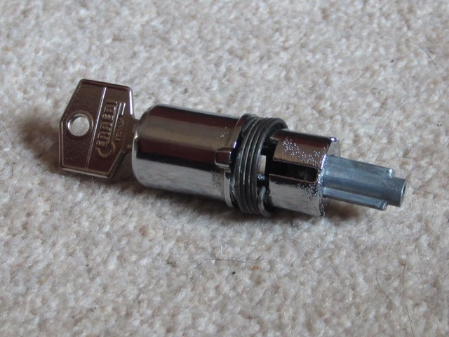 A spring is fitted to the inner end of the lock barrel which ensures it always returns to the aligned position, allowing the key to be removed.
Slotted on to the rear of the lock barrel is a profiled plunger which has two ‘ears’ at its base. The plunger is not attached to the barrel but its movement of travel, both rotationally and in/out, is limited by the shape of the rear of the lock barrel.
The plunger serves two purposes; the operation of both the door latch locking mechanism and the door latch release lever.
Operation of the Latch Locking Mechanism
The rear of the lock consists of a spring between two washers, the lock operating lever, lock end housing and plunger fixing screw. The operating lever and housing both have a hole matching the profile of the plunger.
 The fixing screw ensures that the ears of the plunger are positioned in line with the end section of the lock barrel (when the button is not pressed).
In doing so the plunger is always engaged in the hole in the lock operating lever.
When the key turns the lock barrel, the plunger ears will come into contact with the edges of the lock barrel. At this point the plunger and operating lever will also turn.
 A sprung linkage is attached between the operating lever and the locking lever of the latch mechanism, mounted below on the rear face of the door. Therefore the latch lever will either be pulled (unlocking) or pushed (locking), depending on the direction of rotation of the key.
The purpose of the spring is to provide some resistance in the rotation of the operating lever and engaged plunger. As a result, when the key is turned to lock the door, the operating lever and plunger will remain in the locked state when the key is released which affects the operation of the latch release lever, describe below.
Operation of the Door Latch Release Lever
The hole in the lock end housing allows the plunger to pass through when it is correctly aligned, which is when the door is unlocked. At which point, the plunger ears will be engaged with cut outs in the end of the barrel. Pressing the button will push the barrel inwards and with it the plunger. The plunger passes through the housing until it hits the latch release lever allowing the door to be opened.
In the locked state, the plunger ears are aligned with slots running the length of the rear part of the lock barrel. This time, when the button is pressed and the lock barrel moves inward, it simply slides past the plunger and the release lever is not activated.
Rebuilding the locks
The first issue was only one key was provided which only operated the drivers door and not the passenger door or glove box. So the both door locks must have been changed at some point in time. I could live with having a separate key for the glove box but it would become annoying for the doors.
Unfortunately replacement sets of matching lock barrels haven’t been available for a number of years. After quite a bit of searching I found a classic car lock specialist who could replace the wafers to produce a pair of matching barrels. A couple of days after sending them, a match pair were returned.
By chance, a month or so later, a friend contacted me asking about replacement locks on behalf their friend who has an E-Type out in Harare (their car was first registered in Zimbabwe on 6 January 1970, only 5 days after mine was registered!). I mentioned they’d been unavailable for some time and the hassle I’d had with the locks. When he made some enquiries with SNG Barret, complete barrel sets including the boot and glove box were available and had just come back in stock, for little more than I paid to get mine matched – another case of poor timing on my front!!
With the lock internals removed, the handles and push buttons were sent away for re-chroming. Overall I was pleased with chroming work, except for the handle and push buttons as the plating process had deposited too much material (I think this is quite a common problem). This stopped the buttons from moving once inserted into the handles and also stopped the barrels from being inserted into the buttons.
They were sent back but even when the returned the fit wasn’t good so I carefully removed some material from the inside of the handle with a Dremel. Not only that but I’d accidentally left one of the retaining pins in the button for safe keeping. It was then firmly re-chromed in situ and was not that easy to drift out. I can hardly complain about that as it was my fault!
 Other immediate issues were one of the alloy lock housings had broken around one of its mounting holes and the inner washer, inserted before the large spring, was missing.
To my surprise I found a stall at the Jaguar Spares Day at Stoneleigh that were selling reproduced alloy housings so that issue was easily resolved. As yet I’ve not sourced a replacement washer which I have subsequently found out causes a problem.
 Both locks had become clarted up with dirt and grease over the years. One so much so that it was difficult to rotate the key.
I think the problem is that grease and heavier oils tend to pick up more dirt. I’ve used Lock-Ease graphited lock fluid when putting the locks back together which will hopefully reduce the build up in future. It’s also designed to reduce wear and keep them working in freezing temperatures.
I rebuilt a lock without replacing the missing washer to see if it was absolutely necessary. The lock worked fine which was good news …. until I’d operated it half a dozen times and it began to seize up. The washer sits between the two springs within the lock. Without it the springs start to entangle. I now suspect this was why one of the locks was harder to turn rather than just a build up of grime.
I’m a bit stumped on how to resolve the issue as I’ve not been able to find a replacement yet …..

 A couple of attempts still didn’t reveal an area of compression in the rubber …. more head scratching. It was definitely not the engine as this was almost entirely encased in Dynaliner.
  However this time, when the bonnet was raised to investigate, it revealed a 4-5 inch scrape in the paint on the air intake duct. Gutted.


 I had wrongly assumed that once the mounting brackets had been fitted to the engine, the weight would naturally align their bolt holes with the engine mounts fixed to the frames. After a considerable struggle, not dissimilar to the fitting of the rear suspension, everything was lined up and the front engine mounts could be secured.
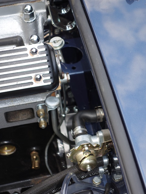 I thought it would be easier to fit the central engine stabiliser once the engine was in place, as it’s one thing less to keep an eye on when the engine is lifted. It’s was fiddly job as there’s very little room between the engine and the bulkhead to get your fingers in. I think I’d prefit it next time.

 The heater valve was another part that was difficult to remove, as the bulkhead heater pipe had seized solid into the valve body. I didn’t want to apply heat in case it damaged any internal rubber seals and so I tried to break the joint by rotating the valve body. All this achieved was to deform the pipe, which eventually had to be cut to remove the valve.
 The rivet was drilled out and then it was fairly easy to split the valve in two by rotating the end cap. This revealed the cause of the weeping – a sprung rubber diaphragm, that is used to control the passage of water, had become furred up.
  Even after extensive internet searches, I haven’t been able to find a supplier that just supplies the internal rubber diaphragm. Unfortunately the options are very limited.
 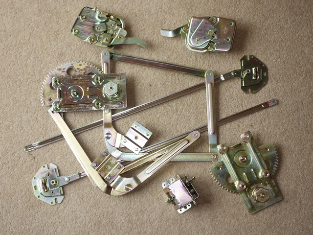 The window regulators and door latches had come back from the platers looking almost like new. The interior space within the door will be subject to a lot more moisture than most of the other areas of the car, so these were given a coating of Dinitrol hard wax.
 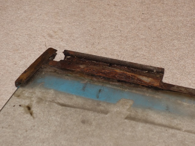 The first was so weakened that it bent when the glass was removed. Fortunately replacements are available but as usual they’re a long way off the quality of the originals.
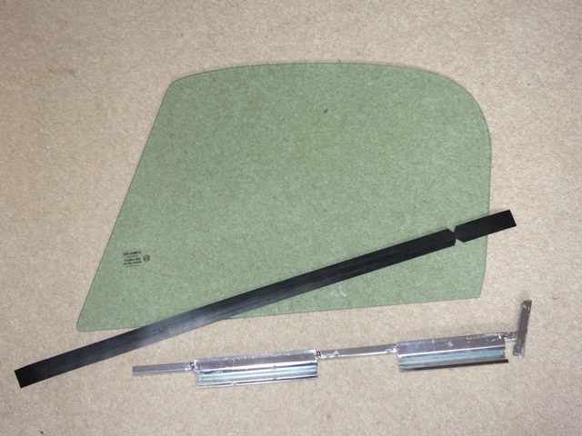 The first trial was to place the rubber in the channel and then trying to insert the glass. As there wasn’t any lubrication, this mainly compressed the rubber into the channel. The rubber had more of a tendency to push the glass out of the channel than hold it in place.

 Quite early on the radiator had been sent off to Northampton Autorads to be ‘re-cored’. It was then stored for a number of years as progress with the restoration ground to a halt. Partly due to lack of time but also a lack of enthusiasm once it became clear how much work was involved in a full restoration.
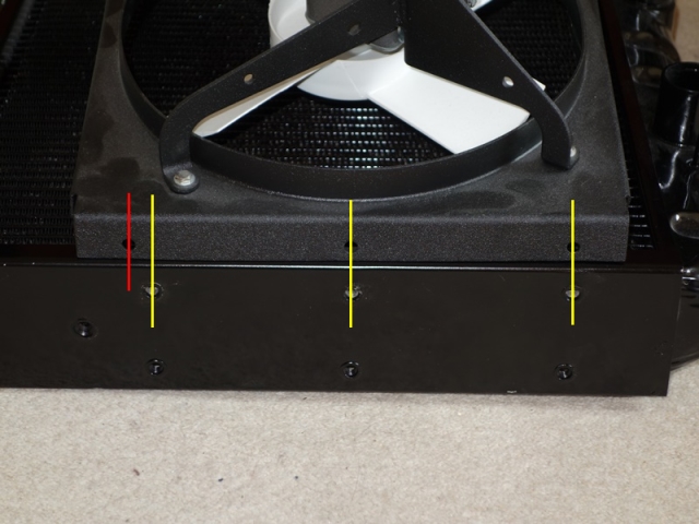


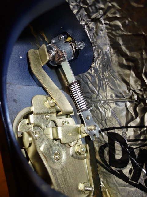
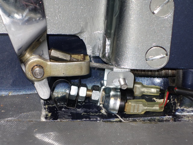 The only way I could get the switch’s plunger anywhere near to the ‘finger’ protrusion was to mount the switch to the bracket and then use two locking nuts to position the spring at the end of the switch – as shown in the photo.
 My handbrake had been hacked about at some time in the past. The bracket attachment has been cut off and welded further back.


 The issues getting the rear suspension fitted meant that there wasn’t time to fit the front suspension let alone the engine.
  The original camber shims had been re-plated and were fitted behind the front and rear mounts. I suspect the shimming will need to be changed when the geometry is finally set up because the new engine frames have been fitted.
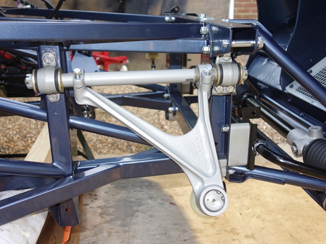


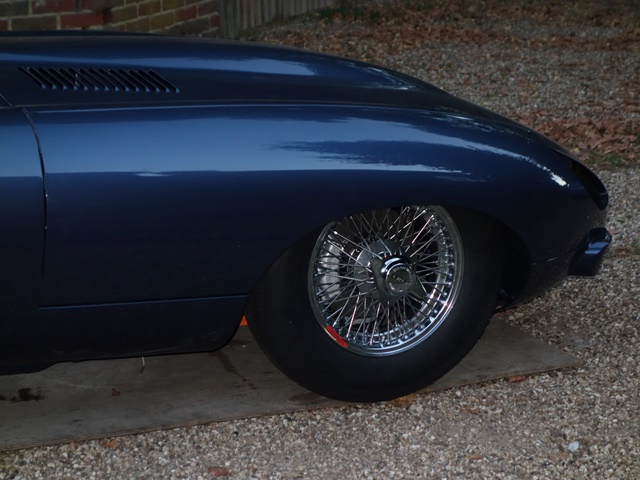

 One of the main problems during the rebuild was the lack of space to store the bonnet out of harms way. It was therefore safer to kept the bonnet on the car and only remove it when absolutely necessary.