
There’s been a dramatic drop off in progress with the restoration in the last month or so. Partly due to the horrible winter weather, resulting in an apathy to venture out into a cold, dark garage!
In the meantime, attention has turned to sorting out bits and pieces that could be worked on indoors, although it gives an excuse for the gratuitous inclusion of some photos of the main reason for the lack of headway … a diving trip in warmer climes!
| Progress is delayed due to a spot of diving …. with some immature 6m Whale Sharks | ||
|---|---|---|
 |
 |
 |
Back to the plot …..
Several years ago I’d come across an owner’s restoration of a ’63 OTS where they had redesigned the looms to their own specification, incorporating relays for the headlight circuits. The addition of relays made good sense, as they remove the main current bearing wires from behind the dash area, but I wasn’t convinced about having bespoke wiring looms made.
Deviating too far from the original wiring looms would mean that, if I subsequently encountered electrical problems, I’d be on my own as it would be hard seeking accurate advice from fellow owners. There was also the fear of overlooking a critical wire when the looms were made up or getting the length of one of the wires slightly wrong. It would be an expensive mistake to fix!
So the idea of adding relays was shelved and a new set of standard looms purchased. Fortunately this proved to be the right course of action. At the time, I hadn’t spotted the wiring diagrams I was using weren’t correct for my car. They didn’t have the changes in circuitry covering the introduction of the ballast resistor into the ignition circuit.
Rather timely, as I was starting to look at the lighting and bonnet electrics, an excellent write up of a headlamp relay modification was covered on the E-Type forum. The installation is very discreet with the relays being mounted out of sight behind the LHS ‘sugar scoop’. The only visible sign of the modification is the main power feed, taken from the alternator B+ terminal.
The downside of tucking the modifications within the bonnet is that it will be much trickier to maintain if something fails. The headlight bowls and possibly the indicators would need to be removed to gain access.
 I had some spare repro 6RA relays so all I needed to purchase were some suitable coloured & rated wires and two in-line fuses. I also decided to install Halogen headlights at the same time.
The circuit diagram shows the planned wiring modifications, with the additional components labelled in red.
There are two spare terminals in the 8-pin bonnet plug, which were originally for the bonnet mounted horns found in the earlier cars and, I believe, the provision for optional extra spot/driving lights.
 One of these spare terminals was used for the single high load wire running from the alternator B+ terminal to the 10-way connector in the bonnet. (It’s much easier to take a supply from the B+ post rather than travelling all the way back to the battery.)
I managed to feed the wire into the PVC sleeving to the bonnet plug so the only visible sign of the installation in the engine bay is a single sheathed wire running from the alternator to the bottom left of the picture frame, which has been cable tied to the existing loom.
From the bonnet connector, this feed splits in two to provide the 12v supplies to the dipped and the main beam relays. The relays have a double spaded terminal for the switched output, so the wires to the left and right hand lamps were connected directly to the relay.
Wire and fuse ratings
The Halogen dual filament bulbs are rated as 55W/65W at 12v so the dipped and main beams for each bulb will draw around 5.5 amps and 6.5 amps respectively (assuming a charging battery voltage of 14.3V).
Normally only one set of the filaments are on at any one time. However the worst case is when the main beam is ‘flashed’ while the dipped beams are on. Even though this should only be for short periods of time, I thought it prudent to assume the maximum current required for both headlamps would be 24 amps (2 dipped @ 5.5A each and 2 main beam @ 6.5A each).
Therefore 44/0.30 cable, rated at 25 amps, has been used for the supply from the alternator rather than the 28/0.30 cable suggested in the forum write up. Inline fuses have been used for the connections to the two relays. Their wiring is rated at 30 amps which is more than enough, although they have both been fitted with 15 amp fuses as the expected loads are 11 amps dipped and 13 amps main beam.
 Using two fuses should ensure that a blown fuse won’t result in the complete loss of lighting!
The original wiring for the dipped beam (Blue/Red) and main beam (Blue/White) will now just be used to switch the relays. The coil resistance for the 6RA relays was measured at approximately 83 ohms so the switching wires will now only need to carry around 0.17 amps. Therefore the dash mounted fuses 1 & 2 have also been replaced, by 0.25 amp fuses.
As the whole bonnet area had been coated in copious amounts of Waxoyl, I also fitted some PVC sheathing to the bonnet loom in an attempt to keep it clean. I just need to tidy up the cabling when the headlamps are fitted.
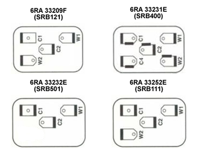
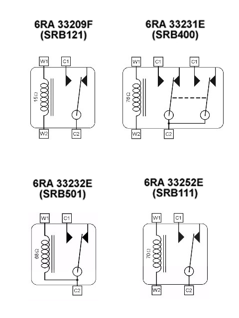 To the right are diagrams detailing the external terminals and internal wiring for the four 6RA relays used in the S2.

 With the exception of the 3-pin cooling fan relay, the W1 and W2 terminals are used to energise a coil winding which has an iron core at its centre.
  The 3-pin relay lacks a W2 terminal because it is designed for applications where terminal C2 is always connected to 12 volts. Internally the C2 terminal is also connected to the coil winding and so acts as the W2 terminal as well, delivering 12 volts. The coil winding is therefore energised by grounding terminal W1, resulting in the switching of the relay.
 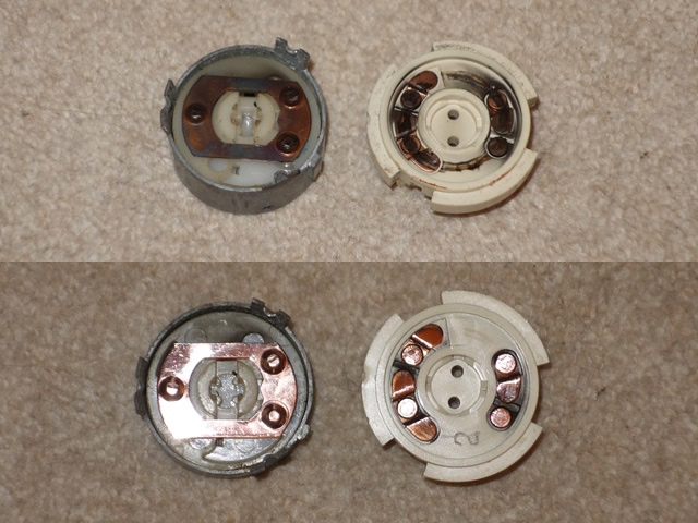 The switch can be split in half by gently prising the retaining tabs outwards. The tabs are made of pot metal so I wasn’t sure they would survive the operation.