 Before the headlights can be fitted, the bonnet electrics need to be completed while there’s still access.
The addition of headlamp relays had been made and so all that remained was to run the bonnet loom from the 10-way connector mounted behind the LH headlamp ‘sugar scoop’ to a 5-way connector behind the RH ‘sugar scoop’.
A small square bracket should secure the 5-way connector and is located on two studs welded to the bonnet. However the stud centre-to-centre spacing was 3/16″ wider than that of the bracket and the holes in the bracket were too small. Yet more cursing of repro parts!
 My initial thought was the bracket was incorrect but that wasn’t the case. The problem was the stud spacing on the bonnet manufactured by the Jaguar Daimler Heritage Trust. It’s a bit worrying if they can’t even get their own bonnets right!
So the fitting of the front indicators and headlamps was delayed until I was able to fabricate a new bracket.
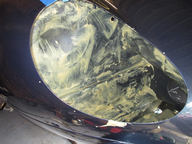
In the meantime I set about the relatively simple task of building up the headlamps in the sugar scoops. The original bowls were on the cusp of being salvageable but, for the relatively small cost, I opted to fit new ones. The first two sets of bowls supplied by SNG Barratt were wrong – the first didn’t have a spring attachment and the holes in the second didn’t align with the holes in the scoops. How hard can this be?
The third set didn’t fit either but the ‘only’ differences appeared to be additional brass fittings on the rim of the bowl and a slightly different location of the lug for the retaining spring. Enough was enough, I decided to use these bowls and removed the offending brass attachments with a Dremel.
(Once the parts are correct) There isn’t anything difficult fitting the headlamp components and everything is self-explanatory.
| Spire nuts fitted to secure the bowls |
Then the rubber gasket |
Orientation of headlamp bowl |
 |
 |
 |
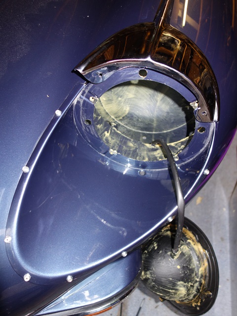
With the bowls in place, the headlight seating rim can be fitted. The rim is attached to the bowl by a retaining spring and two trimming screws. As their name suggests, the latter are adjusted to alter the headlight alignment; one vertically and the other horizontally.
Note: the photos below were taken before I’d realised the bowl, and therefore the adjustable seating rim, needed to be rotated anticlockwise by 90 degrees. The trimming screw to adjust the horizontal alignment needs to be on the offside of each lamp for right hand drive cars.
| Next the headlamp seating rim |
Headlight alignment adjusting screw |
.") |
 |
Kits containing all the components used for the headlamps alignment are available. However the lugs in the new bowls, to attach the spring, were right at the base of the bowl and noticeably shorter. The replacement spring would not reach the headlamp seating rim. Therefore progressively longer springs had to be tried until one fitted sufficiently well and with enough oomph to handle the likely forces due to the weight of the headlamp.
| Standard short spring |
The numerous springs tested |
 |
 |
| Finally one fitted! |
Almost there …. |
 |
 |
It is then simply a matter of connecting the lamp and securing it with the retaining ring. Protrusions on the circumference of the headlamp align with depressions in the seating rim ensure the headlamp will always be orientated correctly.
All the electrical connections within the bonnet were given yet another final connectivity check (paranoia – moi?!?) as there’s no access once the sugar scoops are in place. The bullet connectors were also treated to a good coating of Vaseline to help delay any corrosion.
Fixing the sugar scoops
 The sugar scoops are fixed to the bonnet by special rivets, which are essentially a standard rivet with an aluminium cup under the head. The cups provide a method for mounting chrome finishing beading, which clips on to the cups to improve the aesthetics by hiding the rivet heads.
A spacer washer is also fitted under each of the rivet heads to raise the cup away from the bodywork to allow a rubber strip to sit under the chrome finishing beading.
Originally a single washer was used although others on the E-Type forum have reported needing two washers to get the trim to attach. I guess this will just depend on the relative thickness of the replacement washers and rubber strip.
They also confirmed that the rubber strip originally had holes punched into it, which allows the rivets and spacer washers pass through it in order to sit flush against the bodywork. I had incorrectly assumed the rubber strip also formed part of the rivet ‘sandwich’.
Another suggestion was to Waxoyl all the mating surfaces prior to riveting. I still needed to Waxoyl the bonnet gaps along the front wings before fitting the fitting the chrome beading. So I decided to get this messy job out of the way in one hit and, while I was there, give the areas behind the sugar scoops another thick coating for good measure!
| Waxoyling the bonnet-wing gap |
Rears of sugar scoops |
2nd coating for enclosed area |
 |
 |
 |
The bonnet gaps for the beading were taped above and below in a futile attempt to avoid a major clean up afterwards. This time the Waxoyl container was sat in a bath of boiling water so it became more a job of pouring on rather than brushing on! The bonnet gaps are now well and truly filled with Waxoyl. Although I might come to regret this if (read when!) it starts to melt due to the heat of the engine!
| Position of 5-way connector bracket |
Masking fit for a rivet! |
 |
 |
The paintwork surrounding the sugar scoop area was given the usual riveting protection, a few layers of 3M masking tape, to avoid any damage when the pin snaps off. My plan was initially to use one washer under the rivet heads, as listed in the parts manual. If it was too difficult to fit the chrome finishers I’d have to drill out the rivets and re-do using a second washer. So additional rivets had been ordered just in case.
It was just as well spares had been ordered, as I was soon drilling out all the newly attached rivets to re-do it. Although not to fit additional spacers! I’d been on a riveting roll …. and had been a tad overzealous in their application. The clip to hide the joint between the two chrome finishing strips is held in place by a self-tapping screw. A self-tapping screw that requires a rivet sized hole … well, one that was now occupied by a rivet! What a clot!
| Still blissfully unaware of my error! |
Eyebrow fitting needs the bowl out |
Dooh! ….a rivet too far! |
 |
 |
 |
I only noticed my error as I was standing back admiring how well I’d managed to get the rubber and chrome strips to fit. To make matters worse, somehow the offending rivet had ballooned on both sides of the body panel and couldn’t be pushed through. It required the whole scoop to be removed to sort it out.
Soon after, I also realised that I’d been a bit premature fitting the headlamp bowls and fittings. The front of the chrome ‘eyebrow’ is fixed directly to the scoop by two self-tappers, behind the headlamp bowl and rubber gasket. As it was a new bonnet, the holes for the screws hadn’t been drilled and so all the lamp fittings had to be removed to gain access.
| Let’s have another go! |
Punching holes in the rubber strip |
 |
 |
The scoop was re-riveted to the bonnet for round 2! The single piece rubber strip runs around the edge of the scoop with its ends tucking under the ‘eyebrow’. The holes for the rivets had been created by using a length of stainless steel pipe with a diameter marginally larger than the spacer washer. The thickness of the end wall was ground down to create a sharper edge so it could be used as a punch.
The original rubber strips were shaped so there were different part numbers for each scoop. Unfortunately the replacement rubber comes in straight lengths so it tends to ruffle up as it’s positioned around the curvature of the scoop. It’s not much of an issue apart from around the tip of the scoop, where the curvature is tightest. A heat gun helped to persuade it into shape but I cheated by cutting out a small wedge on the inside edge where a hole had been punched and superglued it back together.
I’m sure there are many methods to fit the bonnet chrome but the one that worked for me was:
- Position the ‘eyebrow’ until it is almost fully home (around 1cm proud of the front wing joint)
- Hook the rubber strip over the rivet heads and feed under the ‘eyebrow’
- Slide, rather than clip, the chrome beading onto the 2nd from top rivet head
- Keep sliding it up on to the top rivet head and then on, until its end is just under the eyebrow. The rubber strip protects the paintwork but care was needed to ensure, if it did suddenly come off the rivet head, it wouldn’t gouge into the paintwork!
- For the remaining rivet heads: the beading has sufficient flex to allow it to be twisted so it fits fully over one side of the rivet head, before pressing it until it clips over the other side
- The front of the eyebrow could then be pressed down firmly to spot the correct positions for fitting the self tappers.
| Slight ruffling wasn’t an issue |
But surgery was needed around the tip |
Re-chroming had distorted the beading |
 |
 |
 |
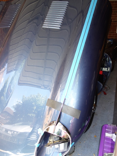
My intention was to fit the long bonnet beading with about 3/4″ extending under the end of the eyebrows. Obviously this required the beading to be fitted before the completion of the headlamps. The only issue was ensuring the brass clips to secure it were positioned away from the bolts clamping the wings to the centre bonnet panel. The gap between the bonnet panels had to be ease open for some of the clips to allow them to slide through.
Easing apart the beading
gap from below |
Pressing the beading home
… v carefully! |
Rod inserted into beading
to stop it lifting |
 |
 |
 |
However extending the beading stopped the eyebrow from being pushed flush against the bonnet. In the end I settled for a butt joint and cut off the extra 3/4″ but adopted another suggestion from the forum: slide a 2-3″ length of small rod into the centre of the beading, leaving of half its length protruding. This engages under the end of the eyebrow but doesn’t stop it being pressed against the bodywork. The rod should stop the end of the bonnet beading being caught and bend out of shape.
Fitting the scoops was a really fiddly job as I’d expected and, with the various problems encountered, took almost an entire weekend to fit the first headlamp (which was the easier of the two!).
I’m still struggling with the second headlamp. The main problems were the dire positioning and alignment of the rivet holes in the scoop compared to the bonnet aperture and the angle of the flange on the scoop.
| A shocking gap using the pre-drilled holes |
The marker pen shows the how far out they were
(and it’s the further of the two marker points!) |
 |
 |
The front of the driver’s side scoop was 5-6mm away from the bonnet panel using the pre-drilled holes. A gap that couldn’t be closed by applying pressure as the underside of the scoop was hard against the bonnet aperture. The only solution was to drill a second set of holes. Also the flange angle down one side was such that it couldn’t fit flush against the bonnet panel. The knock on effect was the ‘special’ rivets weren’t long enough to reach through both panels and longer rivets had to be ordered.
The second headlamp was successfully riveted into position using the newly drilled holes. I was both pleased and relieved and had expected that that would be the end of my headlamp woes. Far from it! I couldn’t get the chrome beading trim on with just a single spacer washer. Reluctantly I decided to drill out rivets and start again using 2 washers per rivet.
 Again the rivets wouldn’t push through once the head had been drilled off. They felt as though they were embedding themselves into the lower panel.
The headlamp was subsequently re-attached using 2 spacers washers under the head AND a washer under the rear. This was to give the blind part of the rivet something firm to compress against so, fingers crossed, they’ll be easier to drill out in future!
The problem wasn’t the number of spacer washers but the shape of the beading trim. I’m certain they had been distorted during the re-chroming as polishing puts a fair amount of heat into quite thin material. It’s not easy to fettle their shape to fit once the chrome plating is on. They can be rotationally flexed but not re-bent to match the scoop contours.
The chrome beading fitted poorly with noticeable gaps caused by forcing the beading to clip onto some of the rivet heads. In fact the addition of two spacers made these gaps worse, allowing the rubber strip to move underneath. This time I’d spent a further weekend ‘not fitting a headlamp’! Rather disheartened, I’ve given up for now and will have another stab once my enthusiasm is restored!
| At least one headlamp is in! |
 |
One they are completed, it will be a job I hope not to have to repeat and I’m now questioning the wisdom of the positioning of the inline fuses for the headlamp relay modification!


