With the vinyl and Ambla fitted, attention turned that next phase of the trimming – the underfelts (or Dynaliner in my case), Hardura and carpets. The decision to fit Dynaliner rather than the jute underfelt was largely driven by the ability to bond the two materials to the silicone side of the insulating Koolmat.
The preferable order of fitting would normally be from the footwells backwards, to avoid needing to clamber over installed trim. At the time, the primary focus was to complete the installation of the inertia seat belts – these would have to be fitted for an MOT, the carpets wouldn’t! However the trimming is quite satisfying so I decided to press on and complete the interior.
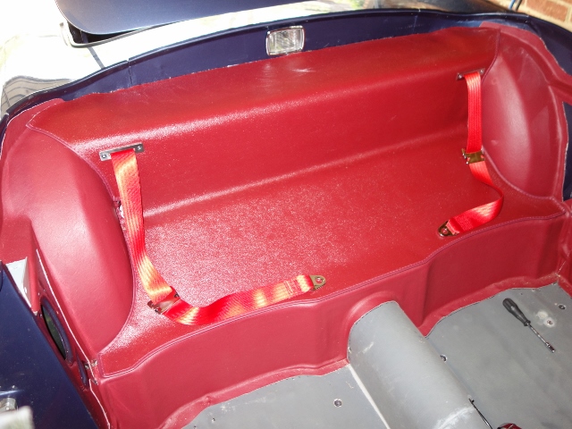
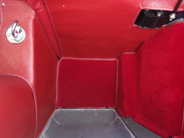
Rear of cabin
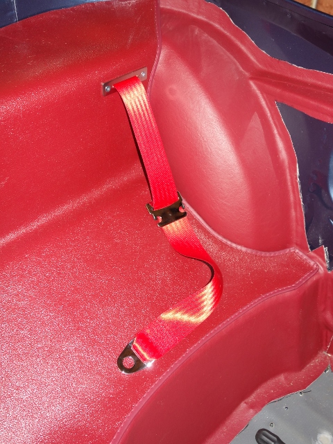
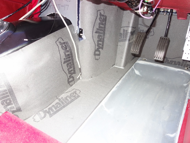
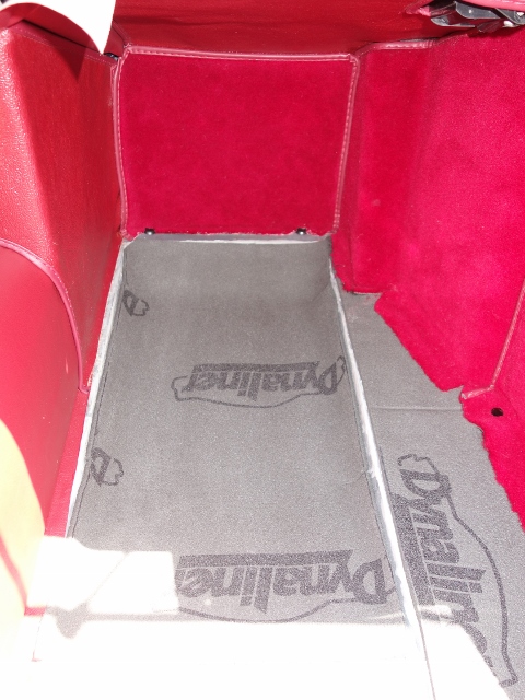
Before the rear bulkhead Hardura could be glued, I first had to rectify the lack of jute/Dynaliner. The excess Ambla bonded to the silver Dynamat had to be lifted so a layer of 1/4” Dynaliner could be inserted. The outer edges of the Dynaliner were cut marginally shorter to provide a channel to hide the body looms.
| Underlay on bulkhead was overlooked |
Re-bonding the Ambla to the Dynaliner |
Ambla with Dynaliner added to bulkhead |
 |
") |
 |
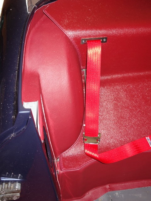
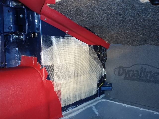
The fitting of the bulkhead panel was fairly uneventful. The strengthening/anti-drumming indentations in the bulkhead panels were taped over beforehand with reinforced cross weave tape. The Hardura was bonded to the Dynaliner in four stages; initially just the leading few inches to fix it in position, then back to the vertical section. This allowed a reasonably tight curve to be made when bonding the vertical section and finally the upper horizontal section, which required a little trimming to butt neatly to the body.
| Indentations in body panels were taped over |
Hardura bonded to vertical section |
 |
 |
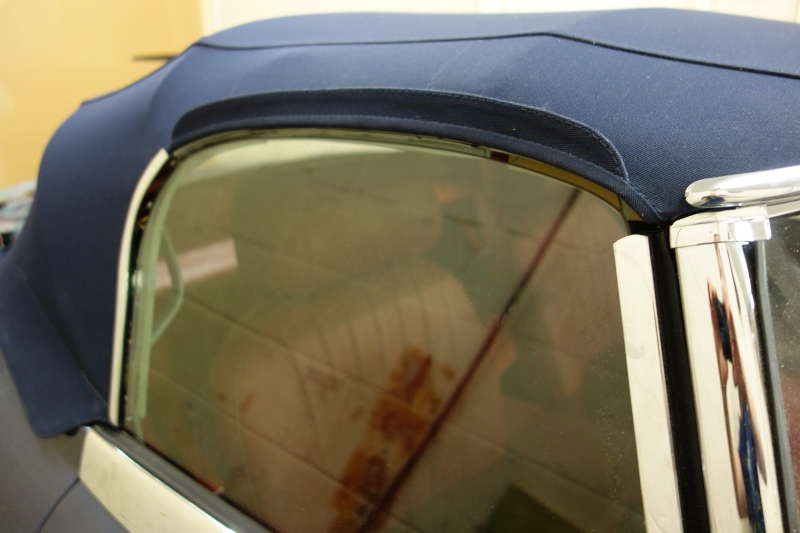
The thin vertical section, from A-post to A-post above the rear bulkhead and wheel arches, is finished with two pairs of vinyl covered panels. Suffolk and Turley suggested leaving these and the door cards off as it would be better for them to fit these when they trim the soft top. The door cards need to be left off so they can make fine adjustments to the angle and maximum height of the drop glass, to ensure the glass seals against the hood’s rubber seals.
Gearbox cover
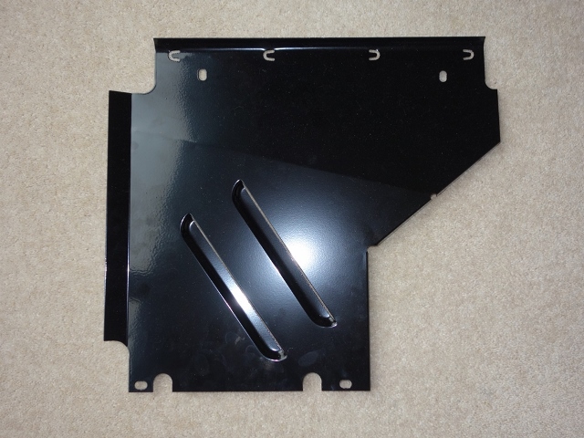
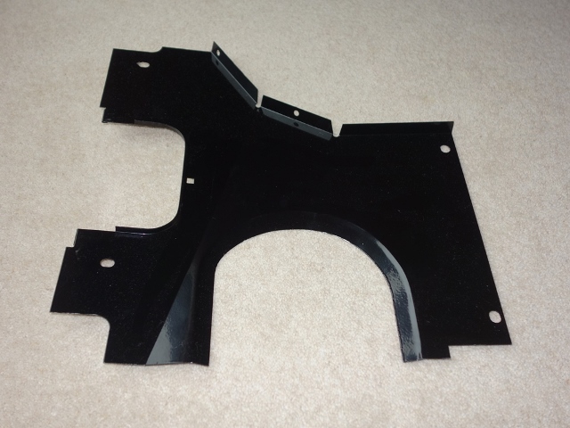
For some reason a previous owner had butchered the gearbox cover by hack sawing off a section around the gear lever. Presumably not satisfied with that, they’d then proceeded to knock seven bells out of the front apron! New metal was welded in to repair and the dents knocked out with a hammer and dolly.
| Many of the cover holes were distorted |
The front apron was a real mess! |
 |
 |
| Otherwise it appeared to be fine! |
Gearbox cover back in shape |
 |
 |
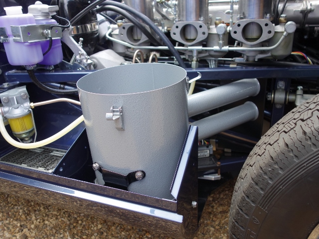
The soundproofing foam that sat between the gearbox and the cover hadn’t stood the test of time so a replacement was ordered. I was expecting to have to cut the foam down to size to fit, however I wasn’t expecting by how much! The 2″ replacement foam made it impossible to even come close in aligning the mounting holes.
The foam also tends to grip the cover rather well so some silicone lubricant was used to help push the cover into place. Even so I had to admit defeat, taking a sharp carving knife to remove foam from around the pinch points. Eventually I managed to get and hold it in position long enough to secure it with a few self tapping screws. If I were to do it again, I wouldn’t bother obtaining a repro foam from one of the usual suppliers and would just make it from a small sheet of 2″ cushion foam.
| The replacement foams are ‘generous’!! |
Secured with self tapper & oval washers |
 |
 |
Floor strengthener carpets
I’m not sure why but I decided to fit the carpet pieces covering the floor strengtheners next. These really should have been fitted at the end, just before the final transmission tunnel carpet is glued in place. So all the trimming of the footwells was spent clambering over them.
The pieces were marginally longer than the circumference of the strengtheners, in part due to the thickness of the additional Koolmat. So they were fitted with the small amount of excess under the seat sections, rather than cut them down to size. I might have to trim them back if it lifts the front edge of the under-seat Hardura too much.
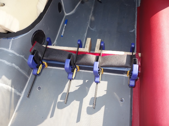
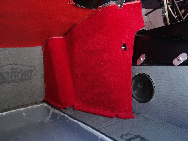
| Masking to bond the front face |
Clamps used to hold in place |
Carpet edging gives neat joint to vinyl |
 |
 |
 |
The three sides of the floor strengtheners were tackled in turn with clamps and/or weights used to hold the carpet firmly in place. The aim was ensure each bend in the carpet was tight against the panel. Although it really wasn’t necessary in the end and it could have been tackled in one go.
Footwell trimming
The general order of fitting for both footwells was:
- Under-dash, toe box and transmission tunnel underlay
- Under-dash Hardura panel(s)
- A-post/Sill Hardura
- Floor underlay next to transmission tunnel
- Transmission tunnel carpets
- Toe box carpet
- Underlay for sunken floor section
- Removable floor carpeting
The reason the two underlay pieces for the floors (4 & 7) were not done at the same time as the other underlay was again to avoid working over them while fitting the other trim. The Dynaliner can be susceptible to tears if not protected.
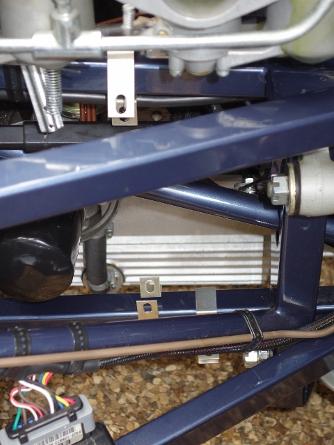
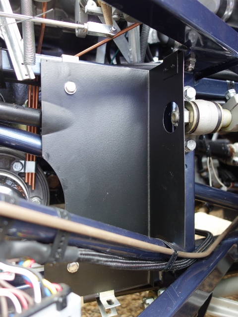
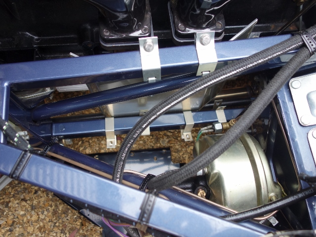
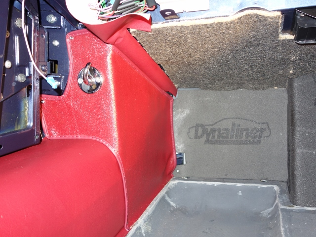
However there are slight differences between the two footwells. Before any underlay is added to the left hand footwell, a vinyl covered conduit panel needs to be fixed along the upper, outer edge. This hides the LH body loom, alternator loom and main loom where the latter two enter the cabin space along the run to the bottom of the A-post.
The conduit panel wasn’t part of the trim kit, which is a bit strange since it needs to be covered in coloured vinyl. The ‘originality’ thread on the E-Type forum was, as usual, very helpful. The shape of the conduit panel changed to a shallower profile during the production run although I think the part number remained the same. The later shaped conduit is available from RM & J Smith Ltd.
| Covering loom conduit |
Accidentally covering the screw holes |
The ‘tail’ will be cut back later |
 |
 |
.") |
I made a mistake with my first attempt, making the vinyl covering to its exact shape. Again from the forum, the A-post end should have a ‘tail’ of vinyl that isn’t bonded. This covers the looms as they bend around the corner of the dash and let in through a cut-out in the under-dash card. The other mistake was to forget to mark the location of the two holes for the self-tapping screws before covering them over! Fortunately I was able to use the previous photos to help locate them with a pin.
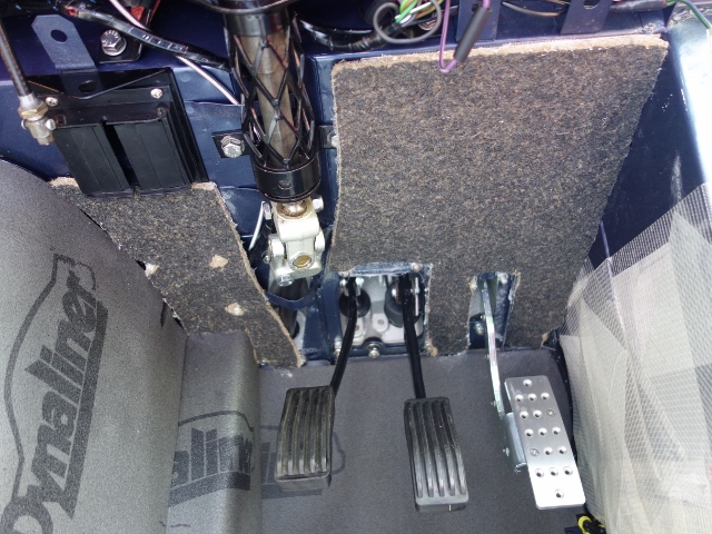
The other differences in the footwells are i) the RH underdash trim is in two sections, sitting either side of the steering column and ii) the LH rear transmission carpet is fixed with snap clips to the floor so it can be lifted to expose the access cover for the gearbox oil filler.
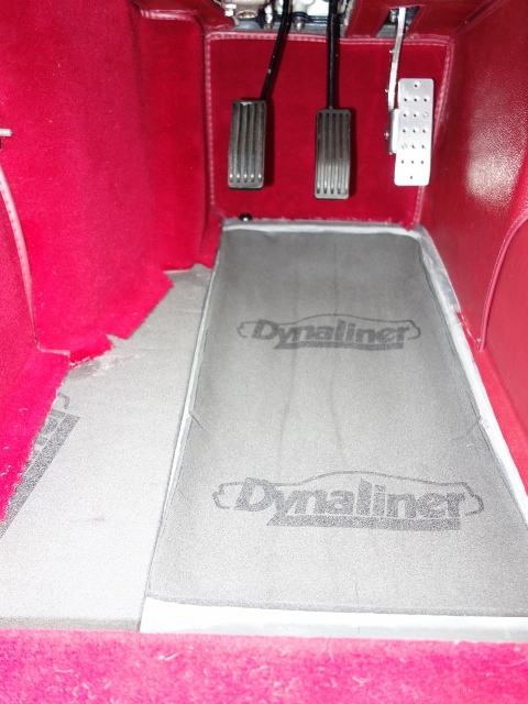
1. Under-dash, toe box and transmission tunnel underlay
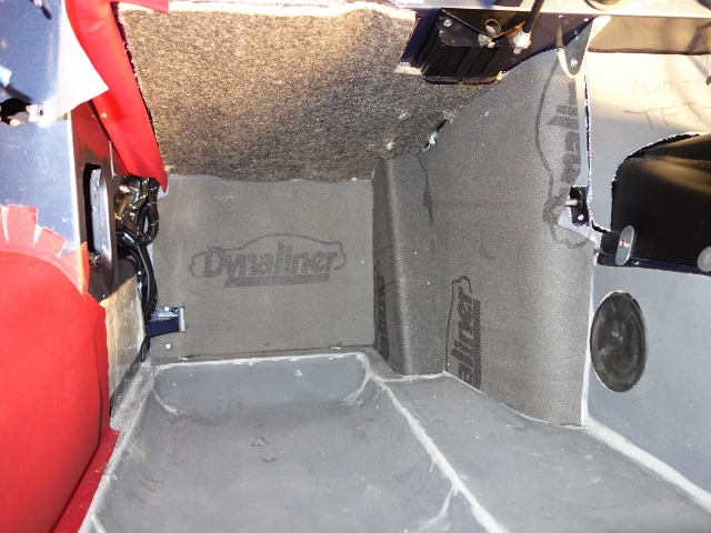
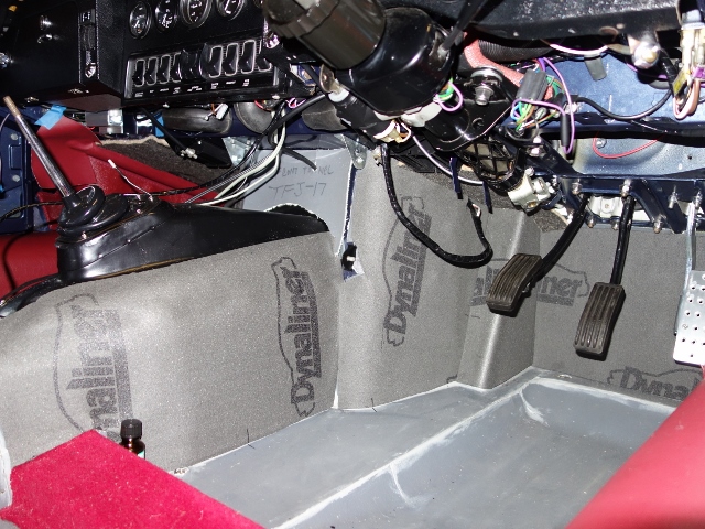
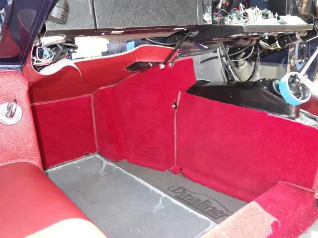
The photos below show the difference between the two footwells – the vinyl covered conduit is the first item of trim to be added to the LH footwell. Also the rear section of the LH transmission tunnel is not covered in underlay to provide access to the gearbox oil filler, via the large, black, circular grommet.
| LH footwell |
RH footwell |
RH under-dash underlay |
 |
 |
 |
2. Under-dash Hardura panel(s)
It doesn’t matter which order the under-dash and A-post/sill Harduras are fitted for the LH footwell, as both butt up against the loom conduit. However, for the RH footwell, the outer under-dash Hardura needs to be fitted first so the A-post/sill Hardura butts up against it.
The outer edges of the under-dash Harduras (apart from the smaller of the RH pieces) are each secured by two 1/2″ #4 self-tapping screws & cups. The excess will be hidden beneath the cardboard dash cards.
| Single Hardura for LH |
Two pieces of Hardura for RH |
 |
 |
3. A-post/Sill Hardura
The surface that these Hardura pieces are glued to is not flat due to the curvature of the sill, the recess for the body loom and the ‘alcove’ in the footwell A-post. More reinforced cross-weave tape was applied to cover these voids to enable the Hardura to be kept as flat as possible. Even so, there didn’t seem to be anything that could be done at the lower toe box corner, due to a strengthening strut.
These Harduras are held in place on the face of the A-post with two #4 self tapping screws & cups (and the bonnet release handle) but bonded inside the footwell.
| A-post footwell voids taped over |
LH Hardura – note #4 screws |
RH Hardura |
 |
 |
 |
4. Floor underlay next to transmission tunnel
Next was the floor underlay beside the transmission tunnel as the transmission tunnel carpets need to be fitted before the toe box carpets.
| LH floor underlay |
RH floor underlay |
 |
 |
5. Transmission tunnel carpets
Transmission tunnel carpet
The transmission tunnel carpet turned out to be the most difficult part of the Hardura and carpet trimming. The carpet bends around two 90 degree bends making it difficult to keep the top edge tight against the Hardura trim above. There’s excess carpet along the lower edge so it’s only the upper edge that needs to be focused on.
I cut out wedges to enable the carpet to be navigated around the two bends and also cut a slit where the tunnel narrows at the rear, near the gearbox cover.
A slot also needs to be cut into the carpet to let in the lower radio console mount. The top edge was simply tucked under the upper console mounting bracket.
| ‘Durable’ snap fastener |
LH transmission carpets |
RH transmission carpets |
 |
 |
 |
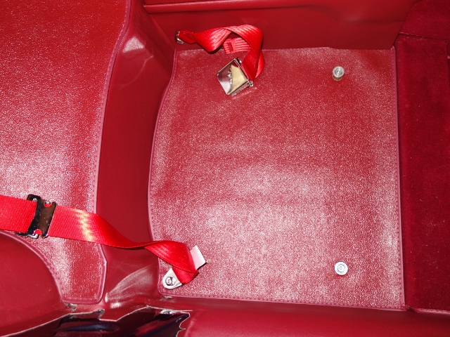
The rear LH transmission carpet needs to lift to gain access to the gearbox oil filler so it is only attached to the floor by two snap fasteners. The upper edge is held under the centre console so no gluing is necessary. Both RH carpets are glued.
6. Toe box carpet
Transmission tunnel carpet
The toe box carpets have finishing edging on three sides. The unfinished lower edge needed to be cut back to provide access to the holes in the floorpan for the carpet retaining studs.
Again, the lower outer corners have to cover the same strengthening strut as the A-post/sill Harduras so it was impossible to get completely flat.
I believe a foot board was also fitted to the passenger footwell to provide the occupant with a foot rest. I’ll have to do some investigation and will possibly fit one at a later stage.
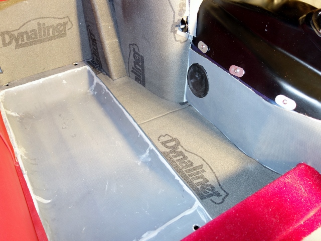
7. Underlay for sunken floor section
The Dynaliner underlay pieces for the floor were bonded by first treating the silicone Koolmat with Loctite 770 (Polyolefin primer) and then using Loctite 406 to bond it.
| LH lining of sunken floor |
RH lining of sunken floor |
 |
 |
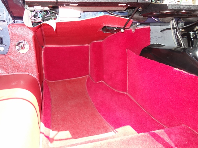
8. Removable floor carpeting
The final trim is the removable front carpets. These are held in place by four plastic carpet studs. Although I’ll be adding these later, during Part 3 – ‘Finishing off the interior’, which will include the installation of the consoles, under-dash cards, seats and seat belts.
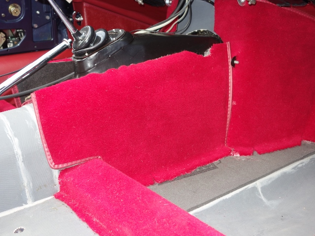
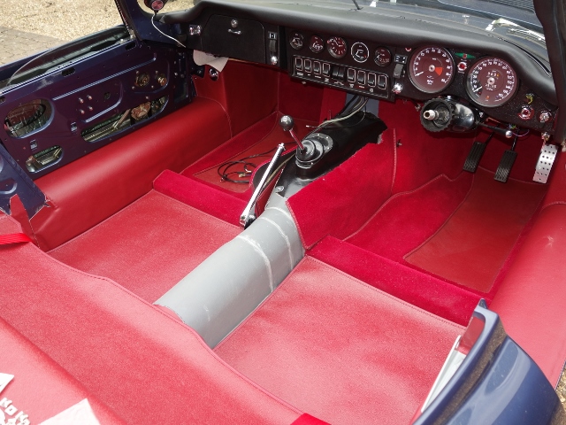
| Completed LH footwell |
Just the consoles to go! |
Interior finally coming together |
 |
 |
 |
The trimming often required the skills of a contortionist and, at times, would best be described as working in a coffin! There’s not a lot of room in the footwells which made masking and the trial fitting and fettling of the various trim quite a challenge. Often all that could be seen from the outside were two legs sticking in the air!

Burning of the trimming rags
The confined space also didn’t help with fumes from the spray-on contact adhesive. At times the nozzle became partially restricted causing unpredictable spray patterns. This required the trimmed areas to be well protected from possible overspray.
So there was great pleasure in marking the end of the trim gluing with the ceremonial burning of the sheets and rags used for masking!