
It has been a long time since the fuel pump had been rebuilt, converting it from mechanical to electronic actuation in the process. Burlen Fuels offer an electronic conversion kit to overcome the known issues with point corrosion with the mechanical set up. While it would have been cheaper to buy a new pump, by reconditioning/converting it, I would gain a much better understanding of how it worked which might prove useful if there are issues in the future.
The electronic set-up had already been tuned to its maximum pumping speed, by rotating a Hall Effect fork. I just needed to check the flow rate was close to the designed 2.4 pints per minute by bench testing it with some paraffin before putting it on the car.
 The pump raced when it wasn’t under load. So far, so good! However when the inlet pipe was placed in the bucket of paraffin it didn’t quite go as planned. It stopped immediately! I tried retuning the electric circuitry by repositioning the Hall Effect fork through its full arc of travel but it still refused to pump. It was a bit gutting having spent all that time and effort.
The technical department at Burlen Fuels thought it might be due to reverse pressure which would naturally slow the pump down. Although I wasn’t convinced as the outlet was simply pumping back into the supply bucket. I was running out of options and was starting to regret not buying a new pump!
I refitted the magnet attached to the end of the diaphragm spindle in the hope that this might be limiting its travel and therefore the strength of the pump. Eureka – the pump continued under load but at a much reduced rate, which would be expected.
 The proof would be in the achieved flow rate which, over three tests, averaged out at 1.6 litres or 2.8 pints. Phew!
I was now happy that the pump was in working order and could be refitted to the car.
 It became apparent that one of the common problems with this SU pump was the tendency for the points to stick, especially on cars stored over winter. After hearing stories of drivers having to use a hammer to whack the pump back into life, I decided it was probably a good idea to upgrade from points to electronic actuation with a kit supplied by
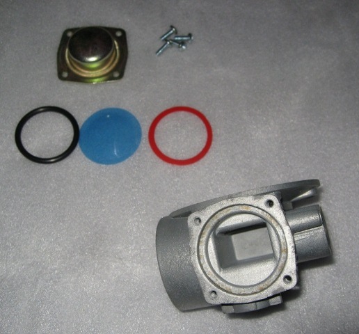


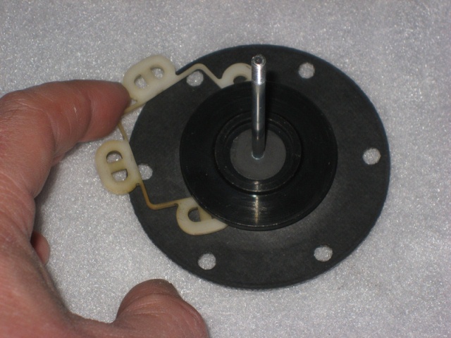 The new armature guides supplied in the repair kit were 5 plastic figures of 8, as shown in the first photo above. The original guide was a single piece and the new guides seemed to be a backwards step rather than an improvement. So the original part was refitted and avoided having to hold five guides in place when refitting the armature/diaphragm into the coil housing.
 Converting the pump to electronic actuation requires a magnet carrier to be attached to the upper end of the armature spindle. First a plastic guide tube is pushed over the spindle down into the coil housing. This centralises the spindle movement within the coil housing. The magnet carrier is fully screwed onto the spindle before being backed off until it is aligned to be perpendicular to the line passing through the pedestal mounting holes. It is then secured in this position on the spindle by tightening an allen screw.
 The bakelite pedestal is replace by a PCB which is mounted on spacers to raise it away from the coil housing. On one of the spacer mountings contains a ‘Hall Effect’ fork. The fork enables the electronic circuit to detect the travel of the magnet carrier and thereby control the energising of the coil.