
At some stage the previous owner had fitted an aftermarket 16″ Moto-lita steering wheel. Even though there was absolutely nothing wrong with it, I was toying with the idea of swapping for either a 15″ or possibly even a 14″ wheel, which a number of owners fit to increase the leg room. The steering would also be more direct with the smaller wheels with the obvious trade off being progressively heavier steering around town and parking.
Still, the unanswered question was, how much heavier would the steering become? Finally I decided to stick with my approach of keeping to the standard specification and only making changes once I’d driven it for a while. However, while I was dithering on what to do, I got distracted by an original rather ropey 16″ wheel on eBay. The wood had dried and split beyond repair so it needed to be re-rimmed … as though I didn’t have enough to be getting on with already!
| 16″ Moto-lita wheel | Original wheel from eBay | Splits in the wooden rim |
|---|---|---|
 |
 |
 |
The splits in the rim ran almost for the full circumference which made its removal very straight forward. Fortunately there are a couple of people offering replacement mahogany rim kits. The new rims are ever so slightly thicker and so will have the benefit of being more rigid.
Unlike the very early E-Type steering wheels, the aluminium ring is entirely enclosed, in a groove cut into the bottom half of the wooden rim. The two halves are then bonded and a gloss varnish applied to the wood.
| Splits made removal a doddle | Aluminium section freed | Replacement rim kit |
|---|---|---|
 |
 |
 |
The Series 2 steering wheels changed from the polished finished to avoid the reflective surface. I wasn’t convinced I’d be able to get a satisfactory brushed effect and so have decided to go for a polished finish.
The numerous scratches and light pitting in the aluminium section were too deep to be removed by polishing alone. So it was necessary to lightly sand it to remove the blemishes, prior to polishing. Initially 600-grit paper was used and then 800-grit until the scratches had disappeared. It was rather worrying at the start as you tend to question whether you’re making it worse rather than improving things!
| Sanding started with 600-grit | Followed by 800-grit |
|---|---|
 |
 |
The grade of paper was then progressively made finer at each pass, finishing with 2000-grit. The aluminium started to gain an even sheen during the last few passes and then it was ready for polishing.
Fortunately I had a second bench grinder and so replaced the stones with two 6″ polishing wheels; one for use with a cutting paste and one for the final polishing paste. I’m sure it would have been a much more difficult task without it or trying to fit a polishing wheel to a power drill.
| Getting close : 1500-grit | 2000-grit produces an even sheen | After polishing with cutting paste |
|---|---|---|
 |
 |
 |
The polishing cutting paste soon obtains a smooth shiny finish. Once the majority of surface blemishes have been removed, the polishing paste is used to obtain the final finish. The key point is to polish evenly rather than over polishing by concentrating on a specific area. It’s surprising how much heat is generated during the polishing process so there were frequent breaks to allow the wheel (and motor) to cool.
The steering wheel boss was also given the same treatment.
 |
 |
 |
I believe the aluminium spokes were originally protected by a clear lacquer. I used Pro-XL two pack clear lacquer which should provide a tough scratch resistant layer, with both the steering wheel and boss given three coats. The curing time is 24 hours after which it can be mechanically polished.
 However, once the aerosol is activated, it only has a pot life of about 24 hours. So it’s not possible to address imperfections in between coats. It was a fine line between getting an uneven orange peel finish and over-spraying causing runs.
I managed to get a combination of the two! Plus a few high spots due to dust pick up and areas where the lacquer flowed through the holes in the spokes and pooled underneath.
The wheel and boss were then rubbed down with 2500-grit wet & dry paper to correct any imperfections, adding a little water to the surface before sanding. A sanding block is a good idea for the wheel to ensure a flat finish.
 |
 |
 |
The lacquer takes on an opaque appearance once sanded so removing areas of orange peel was very easy. Once the glossy low spots had disappeared, producing a uniform opaque finish, it was ready for buffing up with some standard polish. In this case, Menzerna Fast Gloss FG400.
Finally, it was time to re-rim the wheel! A suitable epoxy that had been recommended to bond the rim was Pacer Z-poxy. Several types are available, having different curing times. I opted for the 30 minute variety (PT-39) to provide plenty of time to make any adjustments! Like many epoxies, the resin and hardener are mixed in equal quantities.
 |
 |
To be on the safe side, I chose to tackle it in two stages; first bonding the aluminium wheel into the grove in the lower half and then once cured bonding the top half. The only issue was to make sure the countersunk side of aluminium wheel was the right way round!! Numerous clamps were used when bonding the second half of the rim, alternating between clamping the two halves together and ensuring the edges of the two halves were perfectly aligned.
 |
 |
One of the reasons for choosing Z-poxy was that it can be sanded. However any excess squeezed out by the clamping was quickly removed with methylated spirits. If I were to do it again, I’d not use the clamps to keep the edges of the two halves aligned. Clamping in this way did not squeeze out all the excess epoxy, so there is a slightly more visible join in places. Nothing too disastrous but not perfect.
A better approach would have been to use all 8 clamps to squeeze the halves together a firmly as possible. Any slight alignment issues could then be addressed when the rim is sanded down before the final finishing.
I believe many of the steering wheel restoration companies then apply a hard polyester lacquer to the rim. Although I’ve decided not to go down that route for a number of reasons; it’s not readily available, difficult to apply and I think not as pleasant in the hand.
 My preference is just to apply Colron finishing oil to keep the natural feel of the wood. The aluminium spokes were masked off and the wood sanded down with 240-grit and then 320-grit sandpaper.
The finishing oil was then wiped on with a lint-free cloth and allowed to dry for approximately 5-6 hours between coats. Once each coat had dried, the rim was rubbed down with ultra fine Steel Wool (0000) before applying the next coat.
 Initially the oil produces a matt finish which progressively becomes glossier as additional coats are applied. In the end I had applied about 12 coats until I had the finish I wanted.
To keep the wheel in tip top condition, it should only be a matter of rubbing down with steel wool and reapplying additional coats. Far easier maintenance wise than varnishes or lacquers.
The downside of finishing oil is that it doesn’t offer the same protection against damage that a hard lacquer would provide. I’ll just have to be careful.
| After multiple coats of finishing oil …. the final finish | ||
|---|---|---|
 |
 |
 |
The final problem was the central E-Type motif (or horn push for the earlier cars – the S2 horn being operated via the indicator stalk). The clear plastic had numerous fissures on the surface and some had propagated to reach the base, causing these areas to lose the gold colouring.
| Surface cracks on horn push | Comparison: Repro (L) v Original (R) |
|---|---|
 |
 |
I’d hoped that it might be possible to repair it, in a similar manner to repairing cracks in windscreens. However my investigations so far have not found a suitable method to repair it. The general consensus on the E-Type forum was that it wouldn’t be possible to repair.
A reproduction motif was purchased as a fall back but I hadn’t noticed the differences between the originals and the repro ones until the moderator of the forum pointed them out; the colouring is more of yellowy silver than the deep gold of the original.
Why they can’t get simple things like this right I’ll never know. Chinese no doubt! So I’ll fit the repro one for now until an original comes up on eBay. Fingers crossed …..
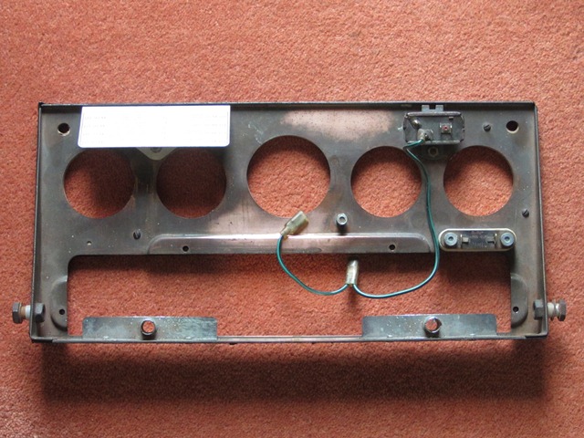
Fortunately the vinyl covering of the dash fascia was in a reasonably good condition and just needed a good clean. Even though only a very mild detergent was used, the cleaning couldn’t bring back the lost sheen and depth of colour. After cleaning, it had an almost whitish appearance in the lower areas of the textured finish.
Apparently vinyl can ‘dry out’ and harden over time so I applied some trim restorer (Gtechniq T4) to see if this would help. The product is simply wiped on and left to dry. It worked a treat in restoring a deep black colour and satin finish. The photos below show the difference in appearance with and without the trim restorer (although the treated areas appear slightly glossier than in the flesh).
 |
 |
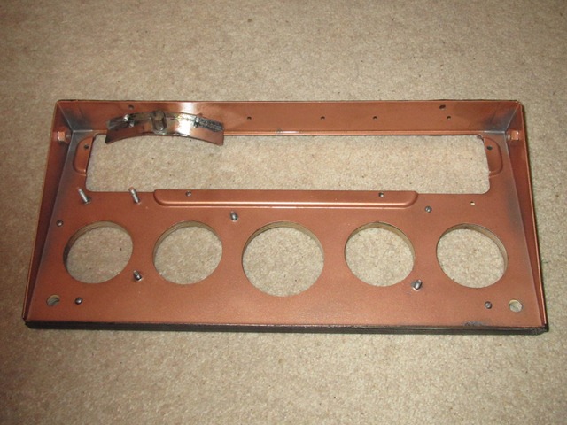
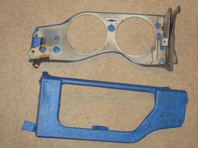
The rears of the facia were treated to a clean-up: Brasso for the copper plated central instrument panel and paint for the outer facia panels. The outer panels were showing signs of rust through the plating in places but it’s not possible to re-plate due to the vinyl coating.
 |
 |
 |
The heater, demister and choke controls were also all looking rather shabby as areas of the wrinkle paint had been worn away. Rather than go down the route of powder coating these, like the cooling fan shroud, I decided to try to get a decent wrinkle finish using an aerosol can ….
 |
 |
…. well four in fact! For the first attempts, Halfords own brand of wrinkle paint was used. Utterly useless! The nozzle failed on the very first application, leaving paint spewing out around the nozzle until the entire can had discharged. I should have opted for the refund but foolishly decided to persevere instead. I’d got through almost the entire can (and my patience!) trying to get anything near to either an even or a wrinkled finish. Both? Forget it.
Common sense returned and I took great pleasure in hurling the remainder of the can into the bin. The next Hycote branded can came from an Auto Factors and wasn’t much better. In a final attempt, I purchased a can of VHT wrinkle paint as I’d found their products to be quite good when painting the alternator and back of the heat shield.
A mock up bracket for a boot light switch was used as a test piece. The instructions were followed to the letter: 3 coats of paint with exactly 5 minutes between applications. The paint goes on with a smooth glossy finish but soon wavy ripples appear. VHT recommend curing the paint by heating to 93 0C for an hour. Two test applications were made: the first left to dry naturally for several days before being cured while the second was left for five minutes before being placed in the oven.
| A gloss finish initially | Dried in ambient temp | Oven dried finish |
|---|---|---|
 |
 |
 |
I preferred the more wrinkled finish produced by immediately curing the paint in the oven. It was easier to spray and cured one side of the levers and knobs at a time. The heater and demister levers simply pivot on the mounting bolt. However the movement of the choke lever is given an incremental feel by a leaf spring pressing a ball bearing, located within a hole in the lever, against a plate with evenly spaced ball bearing sized holes.
| Oven curing | Heater & Demister levers | Choke lever, less leaf spring |
|---|---|---|
 |
 |
 |
A couple of practical but discreet enhancements require holes to be cut into the cardboard glove box. So, rather than butcher the original, a replacement glove box was fitted although like most reproduction parts it wasn’t a brilliant fit.
The top of the glove box is held in place against the facia by a retaining bracket while the bottom edge was originally secured with bifurcated rivets. The only suppliers of these types of rivets sold them by the 1000 and were based on the other side of the world. So standard 3.2mm pop rivets with washers were used instead.
There needs to be a gap between the facia panel and the bottom of the glove box in order to slot in the under-dash cardboard trim panel. Therefore suitably size spacers were needed over the rivet – 5mm thick M3 nylon washers were just about spot on.
| Securing bottom of glove box | USB and Megajolt sockets | Connections hidden from view |
|---|---|---|
 |
 |
 |
As almost all modern gadgets are now powered/charged via the ubiquitous USB socket. I thought it sensible to tuck a double USB socket in the glove box to power phone chargers and Sat Nav while being out of sight. The sockets will be powered once the ignition is switched on.
The EDIS Megajolt unit for the electronic ignition can be programmed by connecting it to a PC via a serial port connection. To avoid needing to remove dash trim to reprogram, I’ve also put a 9-pin serial socket in the glove box. This is permanently wired to the Megajolt unit so any future programming of the electronic ignition system should be a doddle.
The outer heater and demister cables are clamped to a bracket mounted on the bulkhead. The only error I made was to connect up the interior heater valve cable before routing the inner cable through the valve’s trunion in the engine bay. It’s then impossible to fit the trunion onto the heater valve.
The positioning of the USB and serial sockets had to take into account the rear clearances as well as the routing of the demister tubing. With the dash fascia completed, next I’ll have to tackle the LED lighting for the various instrument gauges.
 |
 |
Update:
A while back I had been looking at adding either intermittent or even automatic wipers. However I’d shelved the plans as I hadn’t come across anything that could easily be reverted back to the original setup.
 Once again a couple of the main protagonists on the E-Type forum had investigated suitable units and worked through how to incorporate it into each of the E-Type variants. So other owners wishing to do likewise have detailed fitting instructions and needn’t go through the pain of trial and error installing it. It even covered various mounting positions; either using a blanked off hole in the dash or more discreetly under the dash.
I decided to mount the intermittent wiper module, manufactured by Hella, in the hole in the dash above the Handbrake/Brake Fluid warning light. I’m not sure what this hole was originally used for. I assume either something specific to the FHC or an optional extra. However it was just blanked off on my car.
The unit works by producing a power ‘pulse’ which mimics switching the wiper motor switch on and then off. The wipers start to operate but, as the power is removed almost immediately, the wipers will stop the next time they reach the parked position, ie after performing a single wiping cycle. The frequency of the intermittent wiping is simply varied by turning the unit’s potentiometer knob. I’m not sure about the style of the knob so it might be replaced with a plain black one at a later stage.
 |
 |
 |
It was frustrating to have gone through the process of re-plating/re-chroming all the individual components and to have rebuilt the handbrake, only to find that the ratchet had been butchered to fit an incorrect cable. Rather dispirited, I decided to keep the rebuilt handbrake as is and reuse the offending cable.
I’d hoped that it would be possible to rig up an alternative method of mounting the handbrake switch. However I wasn’t able to come up with a solution that I was happy with. Plus I’d found a number of forum postings of issues setting up the handbrake mechanism even with the correct, unmolested parts.
| Old & New Clevises | Correct cable is shorter |
|---|---|
 |
 was found to be a good 1/2\" longer than the JEC supplied cable. Fitting issues would have been made even worse as the bodged cable abutment had been moved rearward") |
The existing cable was either incorrect for the car or a poor reproduction part. Both of its clevises were far too long, resulting in an inner cable length that was over 1/2″ too long.
I’m fairly sure that a previous owner/garage had relocated the cable abutment on the ratchet about 1″ rearward as a bodge to compensate for the oversized clevis.
 was bodged with the cable abutment at the base moved rearward. The new ratchet come with the spacers welded") The knock-on effect is the distance between the outer cable abutment on the ratchet and that at the handbrake compensator mechanism on the IRS has been reduced by the same amount. Squeezing the outer cable into this shorter distance effectively reduces the overall inner cable length by 1″ – so a net shortening of approx. 1/2″.
The knock-on effect is the distance between the outer cable abutment on the ratchet and that at the handbrake compensator mechanism on the IRS has been reduced by the same amount. Squeezing the outer cable into this shorter distance effectively reduces the overall inner cable length by 1″ – so a net shortening of approx. 1/2″.
The handbrake compensator offers some adjustment to cater for stretching of the cable over time. Even so, 1/2″ would almost certainly put it at the limit of its adjustability. I’d probably be on a losing wicket trying to get it to work correctly. It was better to bite the bullet now rather than later. So a correct cable was obtained from the Jaguar Enthusiast Club, who now offered them via their online shop.
RM & J Smith were able to supply new ratchets which came as a relief, so it wasn’t necessary to buy a complete new handbrake. The only obvious difference is the pivot bolt spacers are welded to the replacement ratchets.
 The fitting of the new ratchet was a simple task but the completion of the handbrake was foiled yet again. The bore of the outer cable abutment was 1/32″ smaller than the 3/8″ cable diameter. It has a slot machined into its circumference and is designed to allow a slight expansion, so I didn’t think anything was amiss.
The bolt securing the switch bracket then clamps the abutment onto the outer cable.
The only way I could get the outer cable into the hole was by continually twisting and pushing it. It didn’t feel right the more I progressed. Considerable effort had been needed just to get the cable half way home. So I decided to remove it and have a re-think. It might be possible to re-drill the bore although I was concerned the slot might cause problems.
 I needn’t have worried. As soon as the cable was twisted in the reverse direction, disaster struck …. one half of the abutment fitting snapped clean off.
Aaaaargh and much cursing of repro parts!! Another case of what I now refer to as the Restoration March …. 1 step forward, several back!!
Looking at the fracture, it appears that the whole ratchet is hardened during the manufacturing process, presumably to provide the necessary hardness in the ratchet teeth. The downside, as I found out, is it makes the part brittle and prone to stress fractures. Not ideal for clamping parts which need a degree of ductility, such as the cable abutment.
RM & J Smith have been an excellent source of difficult to find parts and, to their credit, were very good, offering to send out a replacement immediately free of charge. They had identified the problem with the size of the hole and returned the ratchets to their manufacturer to be corrected. I had received one that slipped through the net. The following day the replacement arrived and it fits perfectly.
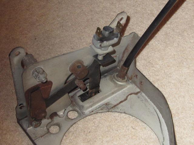
Getting the warning light switch properly set up proved to be much trickier than I’d anticipated and quite frustrating. The switch is activated by a ‘S’ shaped spring striker. When the handbrake is fully released the protrusion at the base of the lever presses against the striker, which in turn depresses the switch.
 The main problem was mounting everything far enough forward so there was sufficient pressure on the striker to operate the switch.
Both the switch and striker are mounted to the bracket by two locking half nuts. So there is very little fore and aft adjustment that can be made. Mounting the switch progressively nearer to the striker starts to pre-engage the switches’ plunger, making the switching more hairpin-like until ultimately it’s permanently on.
I finally got it set up and working on the bench although I still wasn’t 100% happy. The switch had to be angled slightly and the warning light would be on as soon as the lever was moved off the end tooth of the ratchet. The plan was to mount the pre-built handbrake and switch but much to my dismay, I’d completely missed that fact that the cable has to be fed forward into the cabin through a guide bracket in the transmission tunnel.
All the set up was then lost, as the handbrake switch needed to be removed to free the cable. In situ, it wasn’t possible to reproduce as good a set up as before because the floor pan was stopping the angling of the switch. I found the best fit to mount the ‘S’ shaped striker horizontally.
I’m tempted to add some packing washers between the striker and bracket to allow the switch to be moved forward slightly. I think I’m going to leave the fitting the central console until after its first MOT so I’ll still have access to the handbrake.
There’s been a dramatic drop off in progress with the restoration in the last month or so. Partly due to the horrible winter weather, resulting in an apathy to venture out into a cold, dark garage!
In the meantime, attention has turned to sorting out bits and pieces that could be worked on indoors, although it gives an excuse for the gratuitous inclusion of some photos of the main reason for the lack of headway … a diving trip in warmer climes!
| Progress is delayed due to a spot of diving …. with some immature 6m Whale Sharks | ||
|---|---|---|
 |
 |
 |
Back to the plot …..
Several years ago I’d come across an owner’s restoration of a ’63 OTS where they had redesigned the looms to their own specification, incorporating relays for the headlight circuits. The addition of relays made good sense, as they remove the main current bearing wires from behind the dash area, but I wasn’t convinced about having bespoke wiring looms made.
Deviating too far from the original wiring looms would mean that, if I subsequently encountered electrical problems, I’d be on my own as it would be hard seeking accurate advice from fellow owners. There was also the fear of overlooking a critical wire when the looms were made up or getting the length of one of the wires slightly wrong. It would be an expensive mistake to fix!
So the idea of adding relays was shelved and a new set of standard looms purchased. Fortunately this proved to be the right course of action. At the time, I hadn’t spotted the wiring diagrams I was using weren’t correct for my car. They didn’t have the changes in circuitry covering the introduction of the ballast resistor into the ignition circuit.
Rather timely, as I was starting to look at the lighting and bonnet electrics, an excellent write up of a headlamp relay modification was covered on the E-Type forum. The installation is very discreet with the relays being mounted out of sight behind the LHS ‘sugar scoop’. The only visible sign of the modification is the main power feed, taken from the alternator B+ terminal.
The downside of tucking the modifications within the bonnet is that it will be much trickier to maintain if something fails. The headlight bowls and possibly the indicators would need to be removed to gain access.
 I had some spare repro 6RA relays so all I needed to purchase were some suitable coloured & rated wires and two in-line fuses. I also decided to install Halogen headlights at the same time.
The circuit diagram shows the planned wiring modifications, with the additional components labelled in red.
There are two spare terminals in the 8-pin bonnet plug, which were originally for the bonnet mounted horns found in the earlier cars and, I believe, the provision for optional extra spot/driving lights.
 One of these spare terminals was used for the single high load wire running from the alternator B+ terminal to the 10-way connector in the bonnet. (It’s much easier to take a supply from the B+ post rather than travelling all the way back to the battery.)
I managed to feed the wire into the PVC sleeving to the bonnet plug so the only visible sign of the installation in the engine bay is a single sheathed wire running from the alternator to the bottom left of the picture frame, which has been cable tied to the existing loom.
From the bonnet connector, this feed splits in two to provide the 12v supplies to the dipped and the main beam relays. The relays have a double spaded terminal for the switched output, so the wires to the left and right hand lamps were connected directly to the relay.
Wire and fuse ratings
The Halogen dual filament bulbs are rated as 55W/65W at 12v so the dipped and main beams for each bulb will draw around 5.5 amps and 6.5 amps respectively (assuming a charging battery voltage of 14.3V).
Normally only one set of the filaments are on at any one time. However the worst case is when the main beam is ‘flashed’ while the dipped beams are on. Even though this should only be for short periods of time, I thought it prudent to assume the maximum current required for both headlamps would be 24 amps (2 dipped @ 5.5A each and 2 main beam @ 6.5A each).
Therefore 44/0.30 cable, rated at 25 amps, has been used for the supply from the alternator rather than the 28/0.30 cable suggested in the forum write up. Inline fuses have been used for the connections to the two relays. Their wiring is rated at 30 amps which is more than enough, although they have both been fitted with 15 amp fuses as the expected loads are 11 amps dipped and 13 amps main beam.
 Using two fuses should ensure that a blown fuse won’t result in the complete loss of lighting!
The original wiring for the dipped beam (Blue/Red) and main beam (Blue/White) will now just be used to switch the relays. The coil resistance for the 6RA relays was measured at approximately 83 ohms so the switching wires will now only need to carry around 0.17 amps. Therefore the dash mounted fuses 1 & 2 have also been replaced, by 0.25 amp fuses.
As the whole bonnet area had been coated in copious amounts of Waxoyl, I also fitted some PVC sheathing to the bonnet loom in an attempt to keep it clean. I just need to tidy up the cabling when the headlamps are fitted.
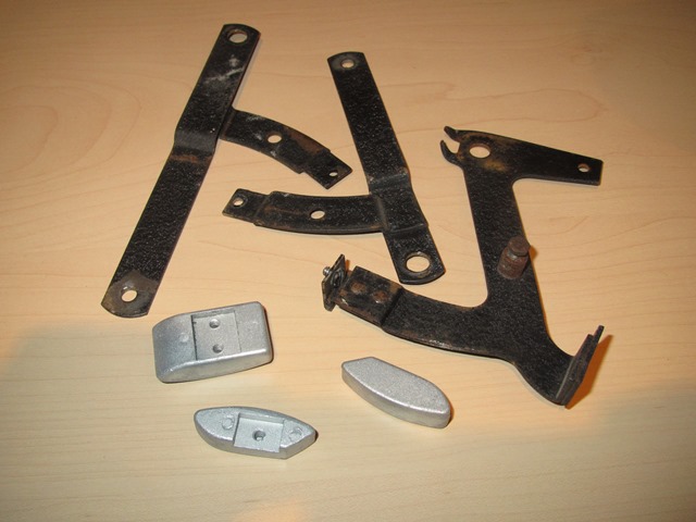
 Unfortunately the heater box was beyond economical repair. The entire bottom section was paper thin and had rusted through in places. The side joints hadn’t fared much better and had rusted from within causing the joints to swell.
Every time the heater housing was rotated to inspect it, showers of rust fell from every opening! The motor and fan cage were also missing.
The heater matrix within is surrounded by a thick felt material and I suspect that this had acted as a sponge. The absorbed water had sat against the base and sides causing them to corrode over a prolonged period of time.
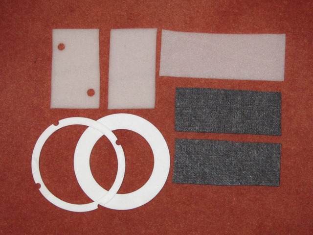 Fortunately new heater units are available (although not that cheaply), so a new one was ordered along with a heater matrix and a kit containing all the various padding materials.
Oddly the padding kit didn’t include the square rubber seal fitted between the heater body and the bulkhead.
If you were going to the effort of replacing all the internal padding, it’s likely you’d be working on the fan housing off the car and so would probably need to replace the bulkhead seal too!
On the positive side, the new heater has an improved design for the fan cage which hopefully might address the reported problems with the original, asthmatic unit. The blades on the original fan cage were flat and aligned radially which isn’t the most efficient in generating a throughput of air. The new cage has curved blades angled towards the direction of rotation.
The heater motor can be switched between two operating speeds and is achieved by introducing a resistor into the circuit to reduce the voltage across the motor. It’s riveted to the motor’s mounting flange and the loom wires soldered in place rather than using spade connectors. I’d stupidly expected a new unit would come with the resistor attached!
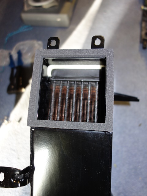
The padding around the heater matrix is a thick fibrous material and it was a really tight squeeze to fit it all in. At least the matrix won’t be able to move around!
I found it was necessary to glue the square foam seal to the heater box with contact adhesive, before fitting the heat to the bulkhead. Otherwise, with only one pair of hands, it tends to fall out of place when attempting the fiddly task of fitting the mounting bolts while supporting the heater unit.
| Heater Matrix & padding | Bulkhead seal glued in place | Heater unit installed |
|---|---|---|
 |
 |
 |
 Fortunately the rubber connectors and ducting behind the dash were all present and in good order. So they only needed cleaning in soapy water to remove the grime that have built up over the years.
As with many other cars of the period, E-Types use Lucas 6RA relays to control the power supply to the various electrical ancillaries, specifically those that draw larger currents. The obvious benefit of using a relay, an electrically operated switch, is it allows a high current circuit to be controlled by an isolated, low current circuit.
This enables all the wiring handling the highest currents to be located within the engine bay and controlled by low current wiring routed from the dash area. Removing the high current wiring from the dash reduces the potential fire hazard.
So it’s odd why Jaguar didn’t use relays to control the main and dipped headlights. The addition of headlight relays is another popular modification which I’ll be making in due course. The mounting of the horns was relocated from within the bonnet to the picture frame during the production run of the S1 4.2. This has freed up a connection in the 8-pin bonnet plug which can now be used for the high current feed from the battery and the relays can be discreetly located behind the headlamp sugar scoop.
Four types of 6RA relays are used in the later S2 cars (those with the ballast resistor):
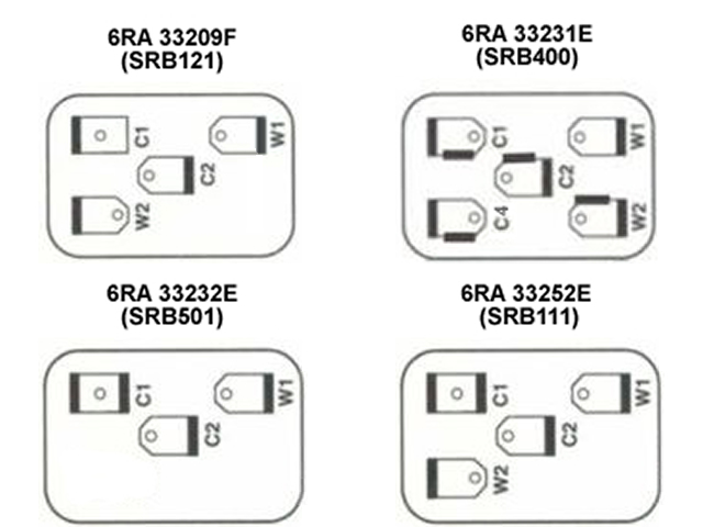
- Alternator Relay – 33209F (SRB121) : 20A 4 pin
- Starter Solenoid Relay – 33231E (SRB400) : double contact 5 pin
- Cooling Fan Relay – 33232E (SRB501) : 3 pin
- Horn Relay – 33252E (SRB111) : 20A 4 pin
Note: the SRB numbers are the modern replacement product codes
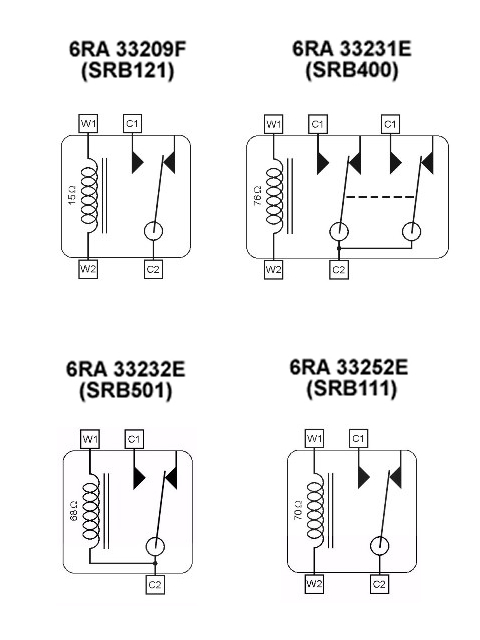 To the right are diagrams detailing the external terminals and internal wiring for the four 6RA relays used in the S2.
The difference compared to the earlier cars is the starter solenoid relay has double contacts to enable it to provide power to the starter solenoid as well as bypassing the ballast resistor while the starter is in operation. All are simple electromagnetic type relays, which are ‘normally open’.
The various relays were all working fine but were showing the effects of decades of exposure to the elements and looked very scruffy against all the restored components.
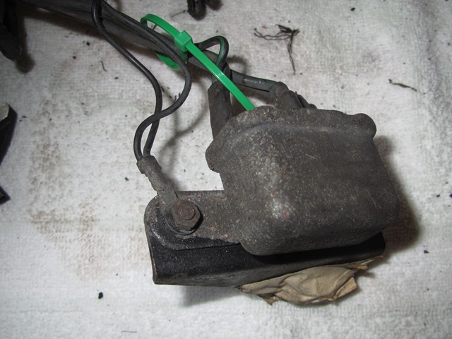 |
 |
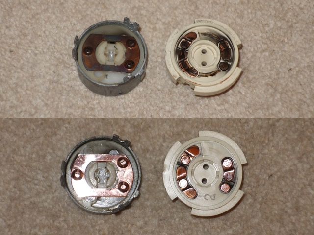
The relay covers are only crimped in four places so it was possible to carefully undo them to enable the covers to be removed. These were dipped in a mild citric acid solution overnight to remove the remains of the zinc plating before being re-plated.
 With the exception of the 3-pin cooling fan relay, the W1 and W2 terminals are used to energise a coil winding which has an iron core at its centre.
In the energised state the coil produces a magnetic field which draws a sprung, iron armature towards the iron core. In doing so a contact at the end of the armature (C2 terminal) makes a connection with a fixed contact, the C1 terminal or the C1 & C4 terminals for the double contact relay.
 The 3-pin relay lacks a W2 terminal because it is designed for applications where terminal C2 is always connected to 12 volts. Internally the C2 terminal is also connected to the coil winding and so acts as the W2 terminal as well, delivering 12 volts. The coil winding is therefore energised by grounding terminal W1, resulting in the switching of the relay.
All that remained was to tidy up the electrical connections and re-crimp the covers back in place.
Ignition Switch
As I was sorting out electrical bits and pieces, attention turned to the Lucas ignition switch, which is marked 157SA 39415A. I’m not sure if this has been replaced at some stage but the terminals bore no correlation to the wiring diagrams and had intermittent connections when tested with a multi-meter.
The terminal connections on the wiring diagrams indicate:
- 1 – Brown : supply from Battery, under permanent current
- 2 – White : under tension only after ignition switch is on
- 3 – White/Yellow : via starter solenoid relay, delivers power to the starter motor
Therefore, when the key is in position II, terminals 1 and 2 should be connected and when the key is in position III, terminals 1, 2 and 3 should all be connected.
To achieve this with my 157SA switch, the White/Yellow wire can only be connected to terminal 1. The other wires using terminals 2 and 3, in any order. I decided to take the switch apart to see if it was possible to ‘correct’ the terminal connectivity and address the intermittent connection problems.
 The switch can be split in half by gently prising the retaining tabs outwards. The tabs are made of pot metal so I wasn’t sure they would survive the operation.
Inside the copper contacts were heavily ‘gunked’, which was the most likely cause of the intermittent connections, so they were cleaned up with good old Brasso.
The key lock engages with a nylon disc within the switch, which therefore rotates as the key is turned. On the underside of the disc is a sprung ball bearing which locates in dimples to differentiate the key positions and a spring which returns the key position from III (starter motor engaged) to position II when the key is released.
There’s no ability to change the terminal connectivity so I’ll just have to adjust the terminal wiring accordingly.
One of the first modifications I’d decided to make was the change to an adjustable reaction plate for the torsion bars. In part the decision was due to the enormous trouble I’d had removing the torsion bars and reaction plate.
Also, even though the front suspension should only need to be set up once, if there was some settling of the suspension after the rebuild, subsequent fettling would be far easier. So I purchased an adjustable reaction plate from Rob Beere and followed Bob Skelly’s excellent installation guide.
![]() – PDF Version
– PDF Version
 I’d planned to install the front suspension and torsion bars on two previous occasions. However, both times, progress had been thwarted due to some other fitting ‘difficulties’ that had been encountered. The first when installing the IRS and subsequently the engine.
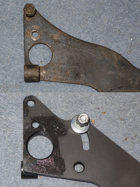
So it shouldn’t have come as a surprise that fitting the reaction plate would be equally challenging! The first problem was the adjustable reaction plate was approximately 3-4mm wider than the original. The tubes for the bolts securing the plate to the underfloor channels protruded much further beyond the outer edges.
Rob Beere suggested using a pry bar and the need for a tight fit, which may well need hammering to ‘persuade’ it into position. If this didn’t work, the ends of the tubes could be ground down slightly to fit. No matter what I tried I couldn’t get it to fit and so had to resort to the latter.
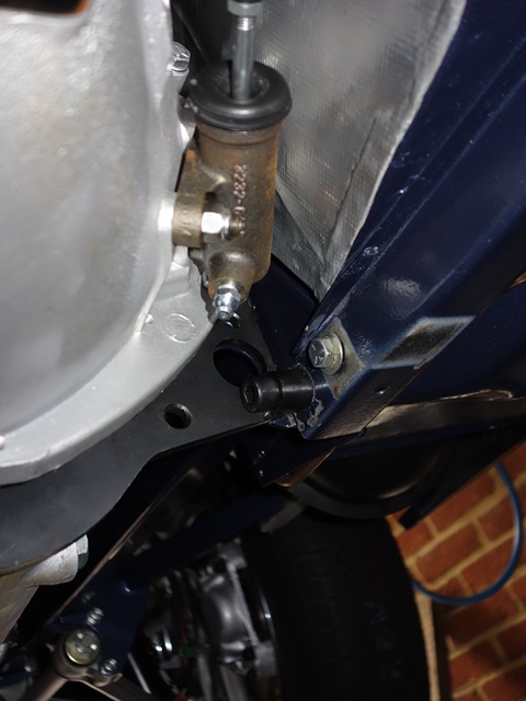 Even so, it still required hitting home with the nylon hammer. The various attempts to get the reaction plate to fit resulted in some damage to the paint work, which will need to be repaired.
Fortunately there are a number of other adjacent areas that still need to be touched up, where the chassis was attached to the support frame during painting. So these can all be tackled at the same time before the exhaust is fitted.
It was surprising to see that the new clutch slave cylinder had started to show some surface rust, even in the short time since the transmission was installed. I’ll have to treat it with some Dinitrol hard wax asap.
Bob’s instructions suggested tightening the large Allen key bolts once the upper bolts had been inserted. However I had slight alignment issues with all the mounting bolts and the torsion bar ‘ear’ brackets. Once the Allen and upper bolts were tightened, it was impossible to fit the remaining bolts and brackets.
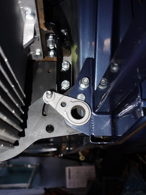 I found it was necessary to have everything initially finger tight, which enabled a screwdriver to be inserted in bolt holes to pry the other mounting holes in the frame into alignment with those in the reaction plate.
The fitting order that worked for me was the large Allen bolts followed by the ‘ear’ brackets, the upper bolts and finally the lower pre-cut bolts.
Only once all these were in place could everything, except the bolt through the ‘ear’, be fully tightened. It is worth reiterating that:
i) the Allen bolts need to be tightened before the adjusting cam is fitted, as the nut securing the cam obstructs access to the head of the Allen bolt
ii) the ear brackets needs to be at the top of their permitted travel before tightening the lower pre-cut bolts.
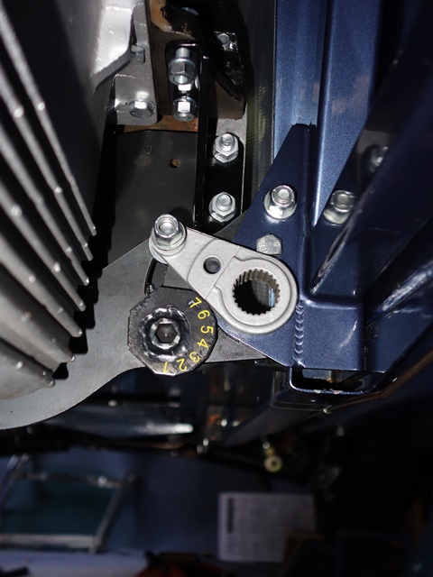 I also followed the advice of labelling the cam steps and then painting the outer face with some clear lacquer. However I didn’t bother highlighting the edges of the steps as I thought this was a bit of overkill.
With hindsight, I think not adding the highlights was a slight mistake. It would have provided a better visual guide to ensure the step of the cam is parallel with the edge of the torsion bar ‘ear’ bracket.
It’s not a major problem, provided there’s sufficient light when setting the cams. If I were to do it again, I’d use two bright, contrasting colours to paint alternate step edges.
I’d not been looking forward to fitting the torsion bars. I hadn’t been able to dismantle them in the conventional manner, described in the various service manuals. There wasn’t even a slight hint of movement in the torsion bars despite some very hefty blows wielding a club hammer. In the end, as an act of self-preservation, I conceded defeat and removed each side of the suspension as single units.
Time for some (dubious) Maths – the torsion bar setting link
The shock aborber is replaced by a fixed length link to provide a datum point when setting the torsion bars. This should then give the correct ride height, although the adjustable reaction plate would then come into its own if it needed subsequent tweaking. The setting link for the early cars was 17 13/16″, however this had increased to 17 31/32″ for the S2 cars.
I’d obtained some replacement torsion bars at Stoneleigh but hadn’t realised at the time that almost all new torsion bars are ‘uprated’. The standard bars are 0.77″ in diameter while the replacements were 0.85″. As a result, the bars will be stiffer, so using the recommended setting link length would result in the ride height being too high …. but by how much?
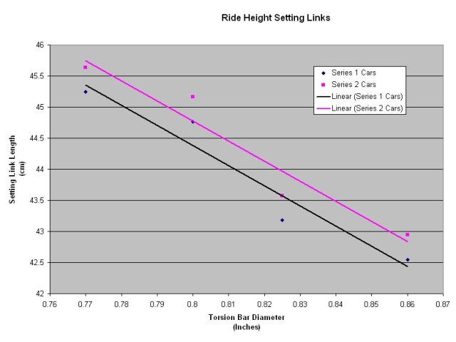 After some research I found that Classic Jaguar in America had produced a chart with recommended setting link lengths for various torsion bar diameters.
Unfortunately they don’t have a figure for 0.85″ bars so I thought I’d plot their recommendations in order to determine the link length required. The graph wasn’t what I was expecting, with a linear relationship between the setting link length and the torsion bar diameter.
Hmmmm! Perhaps I’m missing something as I thought the torsional stiffness or angular deflection of a solid bar was inversely proportional to the diameter to the power of 4. Still, without anything better to work from, using a linear calculation the setting link length needed was 43.1cm.
Fitting of the torsion bars
 The calculated length of the setting link should give me roughly the correct ride height (fingers crossed etc). So I chose to set the reaction plate cam to the mid-setting ‘4’ and will be able to raise or lower the ride height if it’s not exactly right. With the setting link in place and the ‘ear’ bracket locked at setting ‘4’, the rotational positions of the front and rear splines in the suspension are fixed.
The torsion bar has a different number of splines at each end – 25 at the rear and 24 at the front. This provides a high resolution vernier adjustment, allowing the torsion bars to be set very accurately and therefore the ride height. The fitting of the torsion bar is now a matter of trial and error, rotating the bar by one rear spline at a time until the front splines are perfectly aligned with those in the wishbone.
A rotation of one rear spline is equal to 14.4 degrees while it needs 15 degrees of rotation to move on by one front spline. Another way of looking at it is when the bar is turned by one rear spline, the relative position of the front splines is altered by 0.6 degrees, in the opposite direction to the direction of rotation. The front splines will align perfectly for one of the 25 possible orientations!!
 I had passed both splined ends of the torsion bars through their corresponding mating pieces a dozen or so times until I was satisifed it would only need three or four solid blows to hammer them home.
The torsion bar need to be passed rearward through the rear ‘ear’ mounting and then forward again until the front meets the splined hole in the lower wishbone. However the splines were still too tight a fit. It was necessary to carefully file the spline faces on the torsion bar until it only took one firm tap to fully engage the splines.
This enabled the torsion bars to be pushed forward by hand until the front was 1mm or so from the rear face of the wishbone. A tap with the hammer would then bring the bar up to the wishbone, at which point it was possible to determine if the splines were correctly aligned. I used a 12″ pointed concrete chisel for a drift, so the point could sit in the indentation at either end of the bars.
The mistakes I made were:
- Smothering Copperslip over the front splines on both the bar and within the wishbone
- Blindly accepting the view that it’s a matter of trial and error to find the best fit
The Copperslip did a splendid job of masking whether the splines were properly aligned and so it was all wiped off. The best time to apply it was once the correct orientation had been determined and the front splines had just engaged.
I followed the advice of adopting a methodical approach of rotating one spline at a time until an exact fit was achieved. After completing one full rotation I wasn’t convinced I was any the wiser. The correct orientation had probably been missed under the cover of Cooperslip!
It was only at this point did I sit down and work out the Maths of the relative 0.6 degree movement of the front splines for a rotation of one rear spline. A couple of minutes of thought up front would have saved several hours of grief and frustration with a club hammer! Armed with that knowledge, it was then quite easy to quickly home in on a small area of splines spanning the best fit.
As an example:
| Front spline need clockwise rotation | Result of rotating anti-clockwise by one rear spline | Eventually an exact alignment is reached |
|---|---|---|
|
|
|
|


In the left photo, gaps can clearly be seen between the splines. The front splines need to be rotated clockwise to close these gaps. The middle photo was taken after the torsion bar had be rotated anti-clockwise by one spline. The gaps have clearly been reduced.
Eventually an exact or best match is achieved. Although I found when viewed from the lower inboard (7-8 0’clock) the front spline alignment would look spot on. However when viewed from the top outboard position (1-2 O’clock), gaps would be visible.
I think this is because the angle between torsion bar and the wishbone isn’t exactly at 90 degrees. So the lower inbound splines start engaging before the top outbound splines. Hence why gaps are still visible from one view and not the other!
Finally the torsion bars were both in and I’ve now less fear of tackling them again in future.
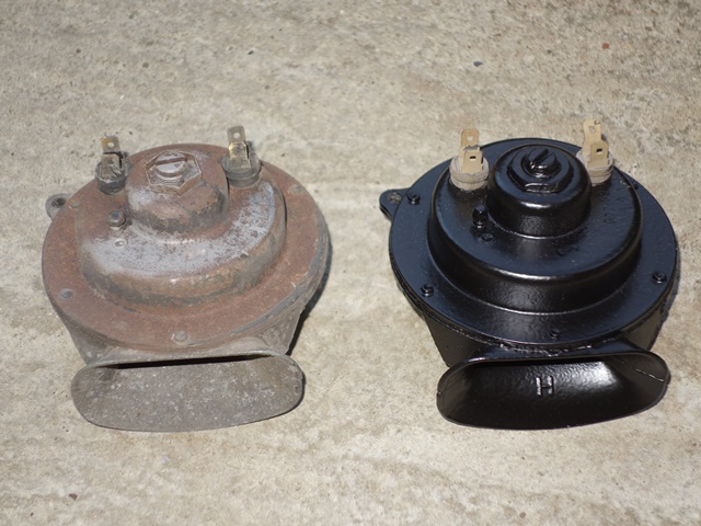
 A pair of Lucas windtone 9H horns was fitted to the Series 2 E-Type, one emitting a high tone and the other the low tone. The excitation of the air column is achieved by vibrating an internal metal diaphragm, with the frequency of vibration and the shape of the horn snail or trumpet determining the note produced.
The switching frequencies are carefully chosen to produce a major third musical interval (spanning 4 semi-tones). Together they set up beat frequencies producing a tremolo affect and a perceptibly louder sound. In the case of the 9H, the low tone switches at 392Hz and the high tone around 494Hz, producing a G and B respectively.
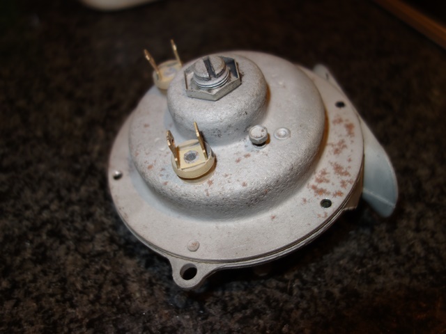
Great in theory, however both my horns were stamped with an ‘H’ on inside of the trumpet indicating they both produce the high tone. Well, they would, if they both worked! One of them only produced a sound for a split second before falling silent. The only recommended external adjustment that can be made is the contact breaker gap via a small screw.
 Rather optimistically I thought it would be just a matter of readjusting the gap to get it working again. Alas, there was something more seriously wrong inside so only the good one was repainted at this stage.
One of the problems with the horns is the two halves are press riveted together. I’ve not been able to find anyone who supplies these rivets so, even if a repair is possible, it won’t be an ‘invisible’ repair.
I’m thinking of using something like Chicago screws but first I need to get inside to find out how it works and if it’s possible to change the frequency. It’s a voyage of discovery from here as I’ve not found any information on the horn innards.
The rivets were drilled and then punched out – the rivet inside the trumpet is slightly shorter than the others so I’ll have to remember that when ordering fixings to hold it back together. The two halves can then be carefully separated as the diaphragm was sandwiched between two thin, wax impregnated gaskets which are quite fragile.
| Drilling out the rivets | Horn carefully split in two | Metal diaphragm removed |
|---|---|---|
|
|
|
|
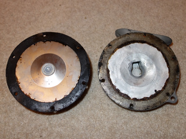
The diaphragm was then removed to reveal the inner workings. Attached to the centre of the diaphragm is a ferrous cylinder so that its movement can be controlled by the rapid switching on and off of an electromagnet.
When current is applied, the ferrous cylinder and therefore the diaphragm is drawn towards the electromagnet. As the diaphragm nears the end of its travel, a disc around the ferrous cylinder hits the base plate of the contact breaker, opening the points. The electromagnetic field then collapses and the diaphragm returns to its natural position and the process is repeated.
 The resistance of the contact points was around 7 ohms so a light rubbing with 400 grit wet and dry soon got this down to 0.8. Although I wouldn’t have thought this would stop the horn operating. I think the problem is with an external screw fitting which the service manual suggests should not be touched.
I’m fairly sure it has been adjusted at some stage as it’s screwed tight against the ferrous attachment. Therefore stopping any possible movement in the diaphragm.
Of the two external adjustments, the small screw adjusts the contact points gaps. The service manual states that this does not adjust the tone and is only to take up wear in the points. The central screw adjustment, with locking nut, only limits the length of travel permitted by the diaphragm so if it did effect the tone it would only be marginal (ie for fine tuning). I doubt it would give anywhere near the variation to recalibrate it to the low-tone.
Hmmmm …. stumped. Going back to first principles, due to the lack of tone adjustment in the electric components. The tone must be controlled mechanically but the spring rate of the diaphragm is fixed. Therefore the only two things that I can see that would effect the output tone are the mass of the ferrous diaphragm attachment, which would naturally impact the switching frequency, and the shape of the trumpet.
Neither of these two can be changed (easily) with the parts I have in front of me! I’ve found a restorer of old horns, Taff The Horns, who might have a non-working low-tone horn to provide a donor for a transplant. Otherwise plan B is to purchase a repro horn from Holdens for about £40!
A whole post on horns without a reference to a sketch by the late Peter Cook!!
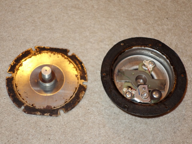
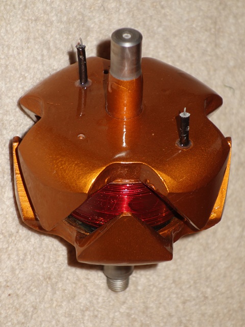
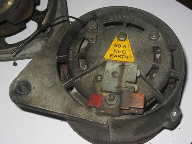
The ‘refresh’ of the alternator turned into a full rebuild because the rotor’s slip ring needed to be replaced, as it was heavily grooved, and the main rotor bearing had seized. In fact, the slip ring was found to be cracked on the underside once it had been removed. Fortunately all the components needed for a rebuild are still readily available.
 As previously mentioned, the Rootes Parts website covers the conversion of the internal electrics to a more modern, self-energising design.
The revised electronics energises the rotor field winding from the alternator’s output, rather than directly from the battery. This produces what Rootes term a ‘soft start’. When the car is started, the output from the alternator is zero, so a much reduced current flows through the field winding as it is wired in series with the more resistive Ignition Warning Light bulb.
The initial current in the field coil is approximately 10% of the normal operating current. However as the alternator output increases up to a typical 14.3v to charge the battery, the voltage either side of the warning light becomes equal, effectively removing it from the circuit energising the field winding. As there’s no voltage drop across the warning light, it goes out and the field winding is now powered directly from the 14.3v alternator output.
Being self energising also has the added benefit that if the belt fails, the alternator output would fall to zero and the field winding current reduces back to 10% of the normal operating current. Thus avoiding the field winding being burnt out.
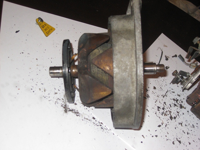 Three screws fix the split ring plate to the rotor. Once removed, the plate can be pulled away from the rotor to reveal the ends of the rotor field winding, which pass through the rear of the slip ring plate and are then soldered at the front to the brass slip rings.
It took a high output soldering iron to melt the solder joints, probably due to the age of the solder, enabling the slip ring plate to be removed.
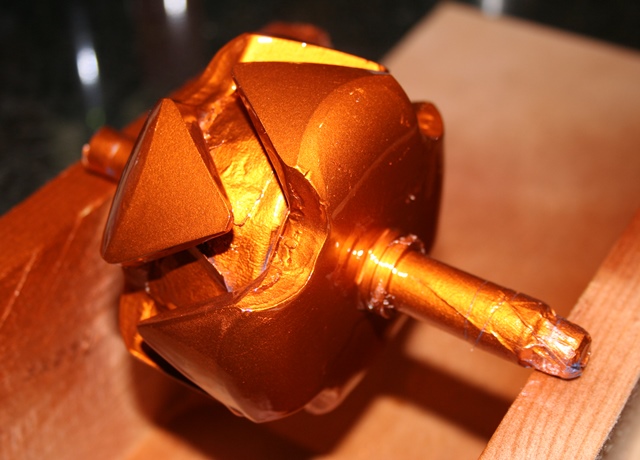
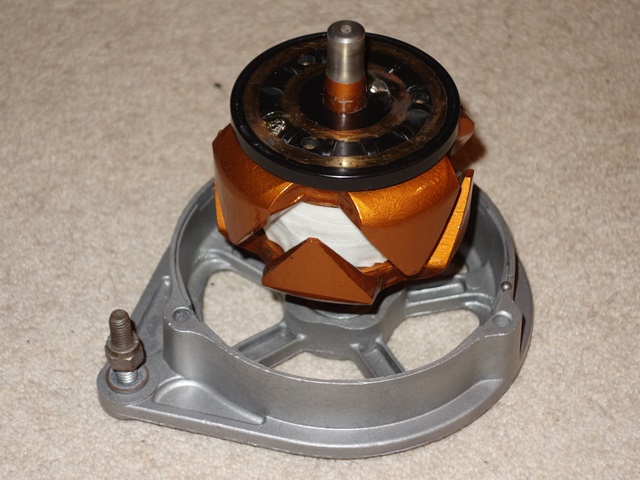
The rotor’s field winding wire is insulated by an enamel coating and then covered by a fibreglass tape so these were protected by masking tape before the rotor was bead blasted, in preparation for painting. The rotor was painted in numerous coats of Burnt Copper and then Clear VHT Engine Enamel paint. VHT paint was chosen due to the high operating temperatures reached and the proximity of the alternator to the exhaust manifolds.
| Painted in Burnt copper VHT | Curing in the oven | Winding re-lacquered |
|---|---|---|
|
|
|
|
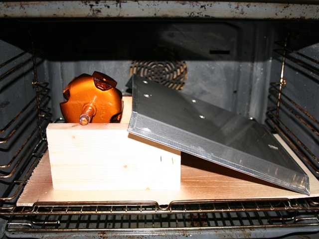
Once the paint had dried, it was cured in the oven at around 100 degrees Celsius for about 45 minutes ….. and, rather sheepishly, the oven then left for a day or two until the aroma had gone! The fibreglass insulation sheaths covering the ends of the field winding had deteriorated and eventually broken free with all the disruption getting the slip ring plate off.
I found an electronics supplier, Brocott UK, who supply the 2mm fibreglass sheathing as well as bottles of motor winding enamel and new fibreglass tape. After the old tape was removed and the winding cleaned up, it was re-coated with a generous coating of enamel. The new sheathing had to be held in place by a small amount of Araldite were it enters the rotor as I needed to ensure the field windings couldn’t short against the rotor body.
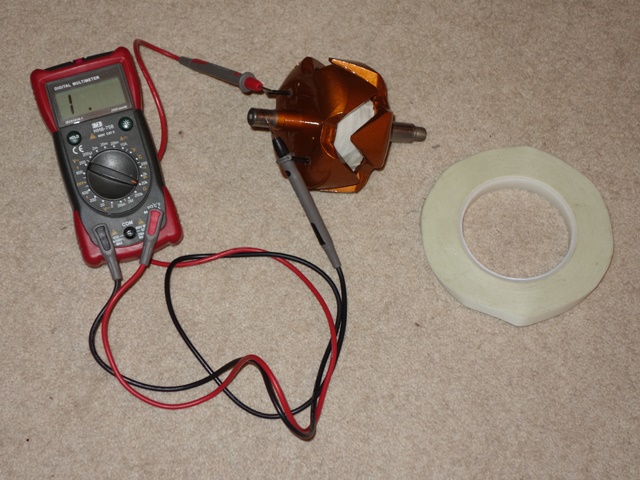
The field winding was re-taped which was a fairly fiddly job, as the 8 prongs of the rotor get in the way. I suspect the winding was originally wound and taped before the two halves of the rotor were fitted together. Before progressing any further, two important tests were made; i) the winding resistance and ii) confirming the field winding wasn’t shorting with the rotor. The winding resistance was 4.2 ohms which is slightly above the recommended upper limit of 4 ohms but I’m happy to leave as is.
| Checking the winding wasn’t shorting | New slip ring soldered and fitted |
|---|---|
|
|
|
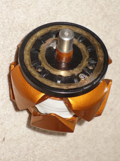
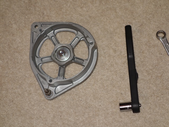
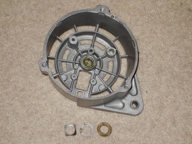
Attention now turned to the fitting of the main rotor bearing. The original had seized and so a replacement bearing kit was ordered. The new bearings are sealed for life units which have a slightly lower maximum RPM. However I was assured they would be fine unless driving at full RPM for prolonged periods.
The outer cover plate and then the rubber ‘O’ ring are placed in the front alternator housing before the bearing is tapped into place. Finally the rear cover plate is inserted and the whole ensemble retained in place by a circlip. I couldn’t compress the parts sufficiently to fit the circlip, due to the thickness of the new rubber ‘O’ ring, and had to resort to clamping them between two suitably sized washers using a bolt. With the bearing installed, the rotor was tapped into the bearing with a nylon hammer.
| Parts of new bearing kit | Compressing the ‘O’ ring | Rotor press fitted into bearing |
|---|---|---|
|
|
|
|
It was only at this point that I found a spacer that is clamped between the inner bearing race and the fan & pulley did not fit. The inner diameter of the new bearing cover was too small to enable the spacer to be fitted. So the whole bearing had to be removed and re-fitted using the original outer cover!
Alternator’s internal electronics
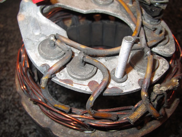 The rectifying diode housing and attached stator were removed from the rear housing by undoing the external nuts on the three terminal posts. Once again I had great trouble de-soldering the joints, this time connecting the stator windings to the diode housing.
The problem is that typical soldering irons, used in electronics, don’t have sufficient output to melt the solder. This is mainly because the relatively large gauged wire used dissipates more heat than the soldering iron can deliver and the diode housing is designed to act as a heatsink.
So I’m now the proud owner of 4 soldering irons, with increasingly higher output ratings! The highest being an 80W iron normally used for soldering stained glass window frames – it was ideal!
The Lucas 11AC alternators use a three-phase bridge rectifier, containing two sets of three diodes, to convert the AC output from each of the three stator windings into DC. Essentially the output of this type of rectifier is close to a DC supply as it is the sum of the positive components of the three AC voltages, which are 120 degrees out of phase from each other.
The conversion involves adding a further set of three diodes to provide an additional DC output to power the rotor field winding. The self-energising alternator no longer requires a 3AW relay so the AL terminal can be re-used for the secondary DC output.
Each terminal post has a variety of insulations and metal fittings – their fitting order was carefully noted as each part was removed to ensure they were correctly refitted during the rebuild, as shown in the photo below.
| Notes taken during disassembly | Parts assembled for the conversion |
|---|---|
|
|
|
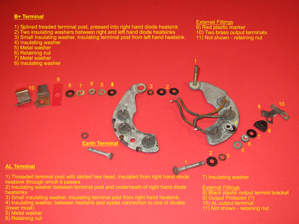

The main points to note are the B+ and AL terminal posts must not short with each other or the alternator casing. With this in mind, the order and purpose of insulators becomes more obvious. The diode housing consists of two halves into each is pressed a set of three diodes. The two halves also act as part of the circuitry as well as a heatsink.
The left hand side is connected directly to the alternator housing via the Earth terminal and provides the common anode connection for the three (negative) diodes. Similarly the right hand side provides the common cathode connection for the three (positive) diodes, which is the B+ output.
The original AL terminal is connected to the wire connecting a pair of the rectifying diodes. This will be replaced during the conversion so the AL terminal is then connected to the output of the three new diodes.
Although the six button diodes look identical, the outer casing acts as the anode for the three inserted into the left hand heatsink (their cathodes being wired to the stator coils) while it acts as the cathode for the other three. Therefore it is essential to ensure they are installed into the correct side of the diode housing. Fortunately most multimeters have a diode test function so it’s easy to check which is which.
The same 2mm glassfibre sheathing for the rotor winding was used to insulate the 16swg copper wire connecting pairs of diodes on each half of the diode housing. Again, the 80w iron made the soldering a doddle. The next step was to install the additional three 6 amp diodes to provide the output for the field winding.
Their anodes are soldered to the anode posts of the positive diodes, delivering the B+ output, and their cathodes are all connected to the AL post. I crimped and then soldered the cathode wires into a 3/16″ eyelet terminal which fits neatly onto the AL post.
| Wiring of the standard rectifying diodes | Additional diodes to power field winding |
|---|---|
|
|
|


There’s not a lot of room between the rectifying diode housing and the rear alternator body so insulation was added to the leads of the additional diodes. Several trial fittings were made to ensure the diode housing did not foul within the alternator body, before finally soldering the diodes in place.
In the meantime the resistance of the stator coils had been checked to ensure all was well before the stator was cleaned up – wire brushing to remove all the rust and then repainting. The stator was then reattached to the diode housing by soldering the coil field wires.
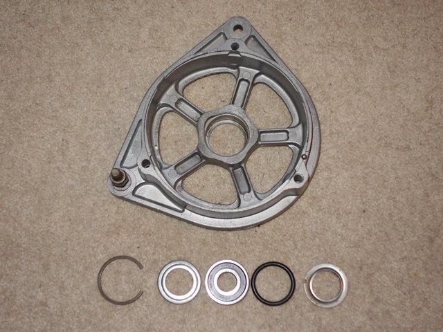
The bearing kit came with both front and rear bearing so the latter was pressed into place and the bearing completed by fitting a felt washer followed by a metal washer and finally a square, spring washer. The corners of the spring washer lock against the alternator housing and hold the other washers in place.
| Rear bearing components | Housing alignment markings |
|---|---|
|
|
|

Two things I wasn’t sure about was whether to soak the felt washers in oil and what grease to use for the bearing. In the end I soaked the washer and opted for a polyurea grease. Hopefully it should be ok! The stator and diode housing could then be refitted to the rear alternator body, taking care to add the various insulating washers.
New slip ring brushes were fitted before reuniting the two halves of the alternator. The two alloy halves have a small dimple marking which both need to be aligned with the narrower and deeper groove in the stator.
The rebuild was completed by fitting the spacer on the rotor shaft followed by the Woodruff key, the cooling fan and finally the pulley.
| Electrical terminals at rear | Front & rear halves reunited |
|---|---|
|
|
|
|
|
|


The only decision left is whether to get the alternator professionally tested off the car or wait until the engine is running …..
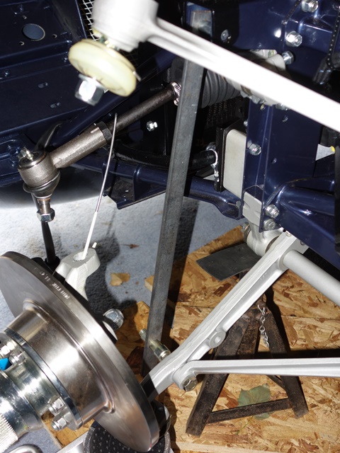
One of the safety features introduced during the production of S1 4.2 cars and carried over to the S2 was a collapsible steering column. The lower section of the steering column housing consists of a lattice structure. In the event of an accident where the steering wheel is impacted with sufficient force, the column’s two upper mounting points are designed to shear and the lattice structure collapse to absorb some of the impact and allow the steering wheel to travel forward.
To enable the column to collaspe, the total length of the inner steering shaft must also be allowed to shorten. To achieve this, the inner shaft is comprised of two sections which are fixed in position by two nylon pins. An impact will cause the pins to shear, allowing the two halves to slide over each other.
The same design is used for the lower steering shaft, connecting the steering wheel column to the rack. Therefore some care needs to be taken when handling and refitting the steering shaft to avoid any heavy impacts and the use of mallets to fully engage the splines!
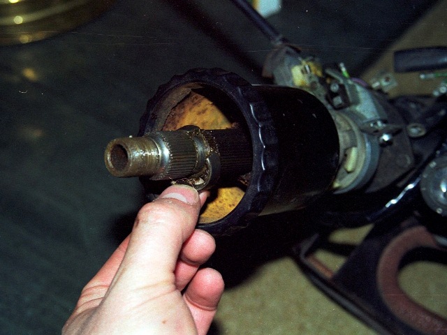
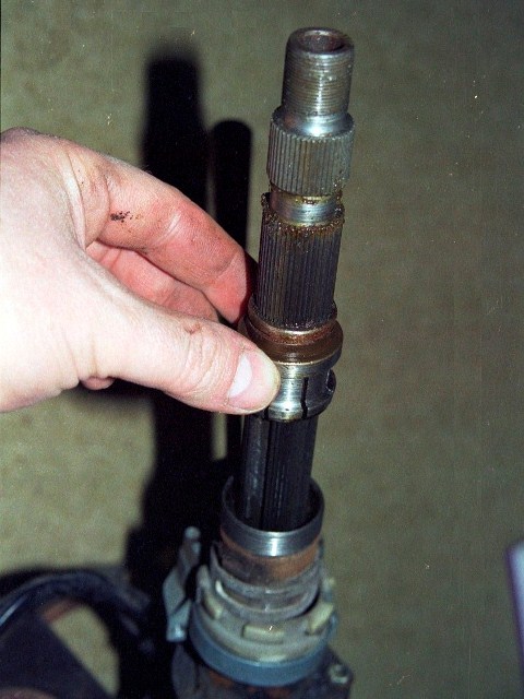
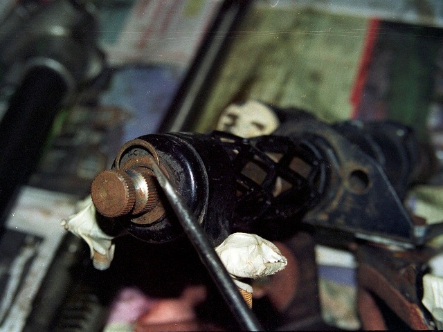
The steering wheel’s fore and aft position can be adjusted by rotating the large black cup-shaped locking nut to release the clamping pressure on a split collet, thus allowing splined inner columns to slide over each other.
Another difference between the early S1 and later cars was that the horn was now activated by pressing the indicator stalk rather than the E-Type motif in the centre of the steering wheel. I assume this might have been partly due to having to make the steering column collapsible but it does simplify the dismantling.
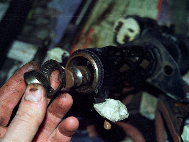
The E-Type motif is normally held in place by three grub screws in the aluminium steering wheel boss but for some reason a previous owner had also glued it in place! It’s removal provides access to the nut clamping the boss against a split cone located in a recess in the inner shaft.
 I was surprising how much force was needed to loosen the nut. It was necessary put on full lock and then use an extension tube over the socket wrench handle to get enough leverage.
It’s just as well I didn’t take it off the car as a complete unit as it would have been a struggle without having the resistance of the steering rack at full lock.
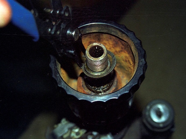
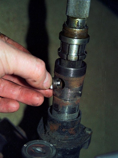
As mentioned, the adjustability in the steering wheel position is achieved by two splined inner columns being able to slide over each other. Their travel is limited by a ‘stop button’ which is screwed through the female inner column and locates in a machined slot in the male inner column.
The steering wheel is then locked in place by a splined split collet, which is attached to the underside of the cup-shaped lock nut by a circlip. When there is no clamping force, the male column is free to move on the splines. However, by screwing the lock nut onto the female column, the collet is compressed and clamps the two inner shafts together.
Once the circlip is removed, the lock nut can be unscrewed and withdrawn, followed by the collet. Next is the stop button to allow the male inner column to be removed.
 |
 |
 |
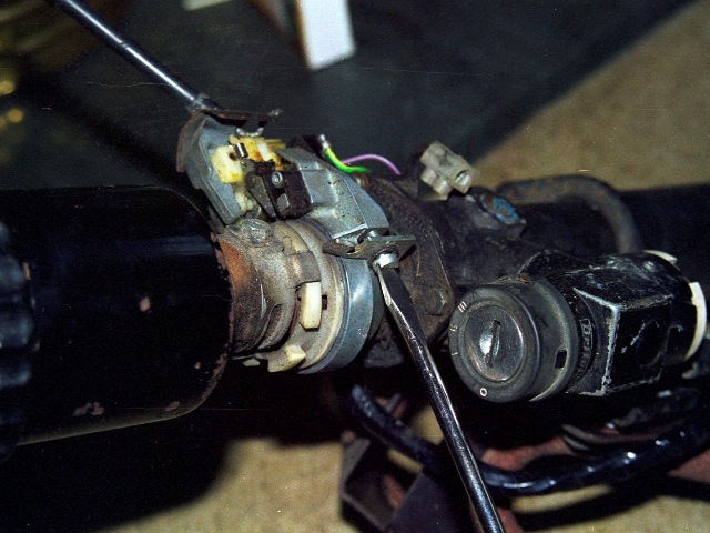
The female inner column passes through the indicator mechanism, attached to the main steering column housing by a semi-circular bracket. Automatic indicator cancelling is built into the mechanism by the use of a control striker attached to the inner column.
 |
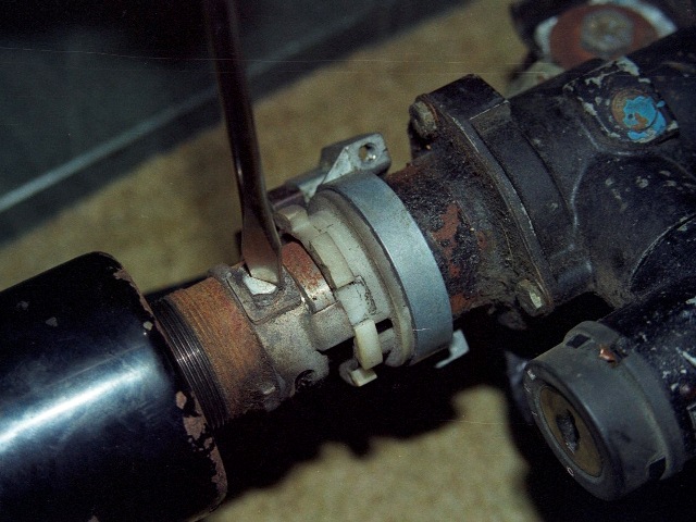 |
The striker interlocks within a white nylon ring in the indicator mechanism so that the ring rotates as the steering wheel is rotated. Protrusions moulded into the nylon ring hit ‘cancelling’ cams which force the indicator stalk back to its non-indicating state when the steering wheel returns towards the straight ahead position.
All that remained was to liberate the female inner column from the steering column housing. The inner column rotates in roller bearings at each end. The lower bearing is held in place by a retaining cover which itself is secured by a circlip and a number of washers. One of which is a wave or spring washer which takes up any free play and provides a small amount of load bearing capacity.
Once the cover and washers are removed, the splined inner bearing race can be slid off the inner steering column and the roller bearing withdrawn. The outer bearing race is simply a press fit into the steering column housing.
 |
 |
 |
The steering column housing’s upper end cover can be removed by releasing the three small retaining bolts.
 At which point the key needs to be turned in the ignition to withdraw the steering lock. This enables the female inner column to be removed.
The ignition switch and steering lock housing is secured to the main housing by a security bolt, which needs to be drilled out in order to remove the lock. The security bolts are designed so the hexagonal part used to tighten the bolt shears, removing the ability to remove it easily.
It’s worth noting that it would be possible to remove the whole inner column as a single unit, even keeping the steering wheel in place, by:
- Removing the lower roller bearing circlip and withdrawing the washers, cover and inner race
- Undoing the three bolts securing the steering housing’s upper cover
- Turning the key in the ignition and withdrawing the entire inner column
This would enable the roller bearings to be replaced without resorting to dismantling the entire steering column.