The target date for starting the engine has been drifting for some time now. In part because I was being a bit too methodical in my approach but mainly because I was getting side-tracked with non-essential tasks, such as refurbishing a second steering wheel!
With Spring in the air, I couldn’t use the poor weather as an excuse either. So a list of tasks has been written that need to be completed before it could be fired up …. for the first time in 18 years!
One of the tasks was to complete the cooling/heating system and fill with anti-freeze. The radiator had already been fitted when the bonnet was off to install the engine. The hoses had been put in place and just needed a few final jubliee clips tightened. So it shouldn’t be too time consuming to complete ….
 Fortunately one of the things I’d been side-tracked with was trying to work out how the lower stone guard, between the radiator and bonnet frame, should be attached. In my haste to install the radiator, I’d forgotten the two rear brackets that fit between the radiator mounting bracket and the mounting grommets.
It wasn’t too difficult to lift the radiator in situ to insert them but the task would have been a lot trickier if the system had been filled and the hoses firmly attached.
I wasn’t too sure of the correct routing for the water pipe connecting the radiator to the expansion tank mounted on the bulkhead. The most logical path was along the top of the picture frame and then underneath the inlet manifold, strapping it to the side of the engine frame to avoid it getting in the way of the carb overflow pipes.
Anti-freeze
 The original anti-freeze recommended by Jaguar was Bluecol, an ethylene glycol based anti-freeze which also contains various corrosion inhibitors. The ethylene glycol anti-freezes are very poisonous to humans and animals if ingested and so they were generally dyed green or blue.
Nowadays most cars use ‘advanced’ OAT (organic acid technology) anti-freezes, which is often dyed pink but, rather helpfully, is also dyed a variety of other colours depending on the manufacturer. Again these have inhibitors but they have been found to cause a number of problems when used in classic cars and are not suitable for systems with copper or brass components, such as the E-Type.
The inhibitors in both types of anti-freeze are consumed over time although more quickly in ethylene glycol. Therefore it’s important to change every two years to avoid corrosion problems. The OAT variety only require replacing every 5 years.
Another additive that some owners recommend is Redline Water Wetter which is designed to improved the efficiency of the cooling system. So 5 litres of Bluecol and some Water Wetter were duly ordered and I was ready to start filling.
Filling the cooling system
Or more precisely how not to fill the cooling system! The instructions suggest checking all the joints for leaks before filling first with 1.5 litres of water, then the Bluecol and finally topping up with water. All perfectly sensible. A quick check confirmed all the jubilee clips were in order and the radiator drainage tap was off, so time to start filling.
 Just as the last 1/2 litre of Bluecol was being added came the dreaded sound of rapidly dripping water, which had quickly formed a pool underneath the heater area. Grabbing a handful of rags I dashed round to contain the leak. Hmmm …. bone dry. However, just to the left, water was gushing out of the engine drain tap. Muppet!!
With the tap closed, filling continuing without incident until about 12 litres had been added. Once again a torrent of water began to cascade over the EDIS coil pack.
Aaaargh! Water was pouring out around the long studs clamping the thermostat housing. The only option was to drain the system to lower the level of coolant until it was below the offending leakage.
 I’d been advised that it wasn’t necessary to use a gasket sealant and the clamping force alone would be sufficient to seal the joints. This advice was now looking rather dubious as I mopped up the pool of anti-freeze that hadn’t managed to soak into the carpet.
Fortunately the ethylene glycol breaks down within a couple of weeks so will not pose a on-going health hazard. The gaskets were dried out and some silicone based gasket sealant purchase for the reassembly.
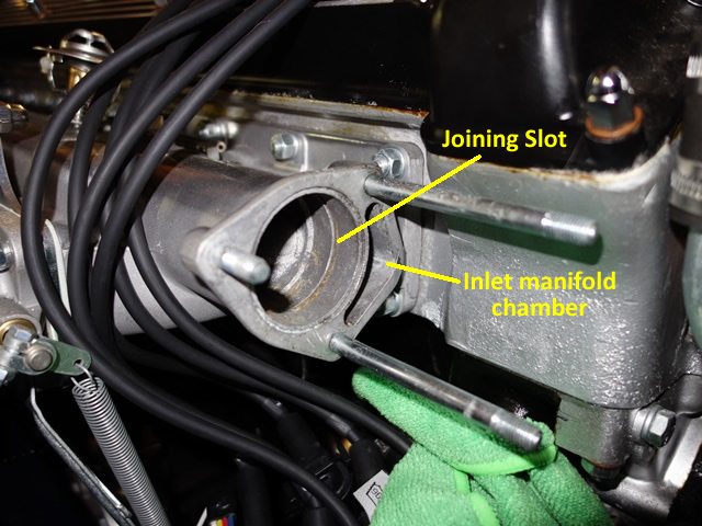
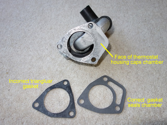
However on closer inspection it was an incorrect gasket that caused the leak. The interface between the inlet manifold and the thermostat housing is an odd one. The inlet manifold has small chamber off the main water channel. The chamber is capped off by a flat face area on the thermostat housing.
I can’t work out what this chamber is for and had assumed it was non-functional as far as the cooling system was concerned. I suspected it was probably providing additional strength to the casting. What I hadn’t spotted was a thin slot joining the chamber to the main water channel.
The triangular gasket supplied did not extend to cover the perimeter of the chamber and so was the cause of the leak, not the lack of sealant. A correct one was soon on its way from SNG Barratt. Even so I decided to use the silicone sealant just to make sure!
Once it had cured for 24 hours, the system was refilled without incident. With hindsight, I should have initially filled the system with plain water to confirm there were no leaks. It could then be drained and refilled, adding the coolant.


 The intention had always been to paint the inside surfaces to provide better protection from the elements. So I decided to keep the new, rusty rear bumpers.


 This in turn raised the rear of the silencer on their mounts so one of the exit pipes was in contact with the floor strengthening panel. This was made worse because the silencers were not welded centrally on their mounting straps.
") They also showed me around their workshops and the many 1,000s of original exhausts they use for templates. I suspect my fitting problems were simply because of the compounded effect of a couple of the bends being slightly out.
They also showed me around their workshops and the many 1,000s of original exhausts they use for templates. I suspect my fitting problems were simply because of the compounded effect of a couple of the bends being slightly out.