
The engine had been rebuilt by VSE with a replacement 123 Electronic distributor rather than refurbishing the original Lucas unit. However a chap, Ray Livingston, in the States had produced a kit for the 6 cylinder E-Types based on the Ford Electronic Distributorless Ignition System (EDIS), controlled by a programmable Megajolt Lite ignition unit.
A number of forum members had already installed his kit and reported on the quality of the machined components and improved running. In the interests of reliability, I decided to do likewise and order a kit as Ray was planning his final batch of kits and only a limited number remained. By chance another owner in Norway was looking for a 123 distributor so I managed to sell him my unused one.
The system has four main components: a trigger wheel & sensor, EDIS module, coil pack and the Megajolt controller. The trigger wheel is mounted to the front of the crank and has a series of teeth around its circumference, which pass close to the sensor. One tooth is missing to provide a reference point for the engine’s TDC. From what I can tell the sensor must use a Hall Effect device acting as a proximity detector to register each tooth as it passes the sensor head.
The signal from the sensor is interpreted by the Megajolt unit’s software to control the EDIS module and the coil pack. The coil pack has a HT output for each cylinder, however the spark for each cylinder is controlled electronically rather than mechanically, as in the original Lucas distributor. The Megajolt unit also has a vacuum input to enable the vacuum advancing of the ignition.
At this stage the key components will be installed but the final wiring and set-up will have to wait until the kit’s wiring loom is in place once the engine has been installed.
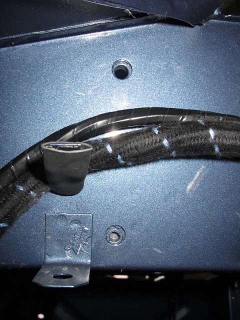 The Megajolt control unit is fitted to the bulkhead just behind the glove box. Rather fortuitously the mounting points for the steering column is exactly the correct spacing for the Megajolt unit, so the unused LHD column bolt holes are used to secure the unit to the bulkhead.
However I couldn’t screw in the lower mounting post as the bolt hole was smaller, unthreaded and blanked off. After much head scratching I decided to re-tap the bolt hole to the correct diameter. This wasn’t successful either and then it became clear what was wrong – the hole has been plugged with a plastic insert which just had to be pushed out!
The Megajolt unit can be connected to a PC’s USB port to programme the desired ignition timing curves although it is pre-programmed with standard curves out of the box. The connections won’t be accessible once the dash is in place, so I’m planning to add a surface mounted USB port to the rear of the glovebox.
The kit provides a replacement blanking plate for covering the unused LHD accelerator opening. The plate contains holes for the unit’s wiring harness and vacuum pipe. However I wanted to keep the installation a low key as possible and took a leaf out of the book of a member of the E-Type forum, and route these within the bulkhead and exit via the hole for the speedometer cable. All that would be required was a larger grommet.
|
|
|


The wiring harness travels along the LH engine frame close to the EDIS module located next to the vacuum Reservac tank. The remaining components, the coil pack and trigger wheel & sensor, are mounted directly to the engine.
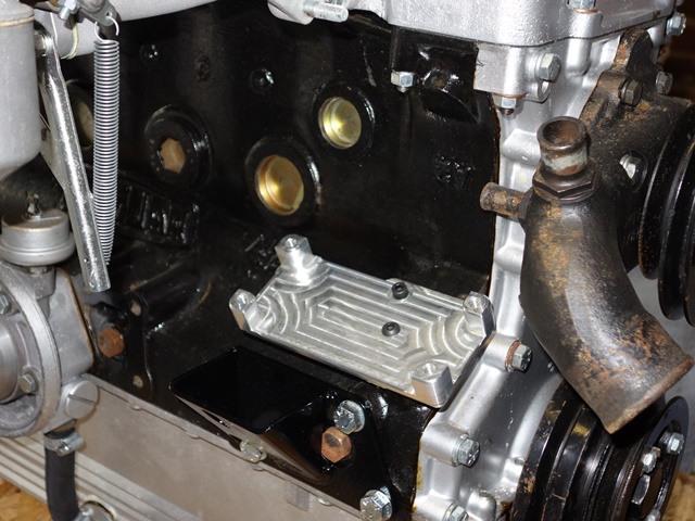
The coil pack is bolted to an aluminium bracket mounted directly into the hole for the standard distributor and so should be a reasonably unobtrusive modification.
|
|
|
|


The fitting of the crank sensor and trigger wheel was the only tricky part of the installation simply because the positioning of the trigger wheel needs to be aligned to TDC. The sensor bracket is mounted using two of the timing cover bolt holes and is adjustable so the optimum gap can be set between the sensor and the trigger wheel.
However the sensor has to be removed to slacken the bolt to adjust the gap. This led to a rather iterative approach to setting it up but nothing to difficult.
|
|
|
|


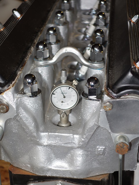
The engine had just been rebuilt by VSE so the positioning of the TDC mark on the damper should be spot on but I decided to check anyway. Another eBay purchase was a dial indicator with a spark plug adaptor to accurately measure the engine’s TDC before the trigger wheel was fitted. Great in theory, however the adaptor’s plunger was too short to reach the piston head even at TDC.
Hmmm …. a high-tech replacement plunger was knocked up out of a short length of 3/16″ brake piping flared at one end and some masking tape to bring out to the bore of the adaptor. I found the easiest method of rotating by hand was to remove all the spark plugs and use a large torque wrench on the crank nut.
|
|
|
|

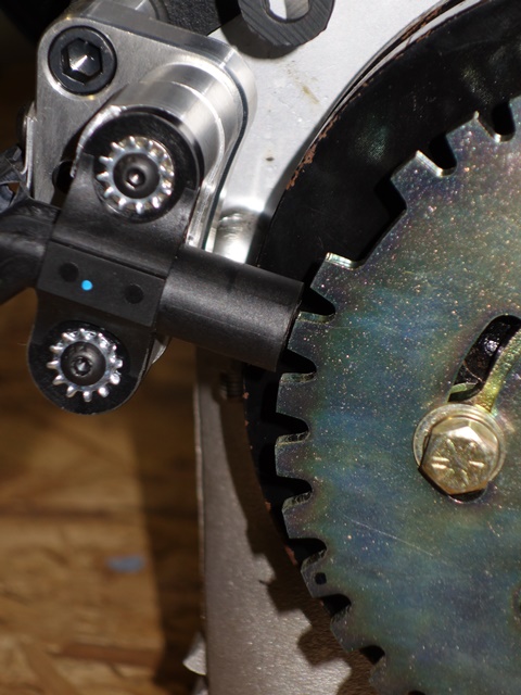
Once I was happy that TDC had been achieved, the trigger wheel was temporarily attached to enable the re-checking the sensor gap for a full rotation. The last step was to check TDC again before the applying Loctite to the trigger wheel bolts one by one.
Fingers crossed everything is correct and the engine will fire first time!
Update: the engine fired up on the first turn of the key!!
Sorry, the comment form is closed at this time.