
Even though the engine was started last year, there were a number of outstanding issues and tasks to complete the fuel system. The most concerning was the new fuel tank didn’t fit! At the time, it was just left in situ and the fuel lines connected while the engine was fired up. Refitting had to wait.
Carburetter Overflows
First, however, was the replacement of the three carburetter overflow pipes. At some stage these had been replaced by shorter pipes. Functionally there was nothing wrong with them but they should come together near the oil filter and be held in place by small clip.
| The short pipes will be replaced | New pipes from Burlen Fuels |
|---|---|
 |
 |
Everything is available from Burlen Fuels although they offer two lengths of overflow pipe: 19” and 25”. The length of the shorter pipe would have been marginal for the rear carburetter so I opted for 25” pipes …. just in case. With hindsight, 19” pipes should have been ordered for the front two carburetters as the distances are much shorter.
I had decided to replace these once the engine had been fitted. While it would have been much easier to shape them when the engine was sitting on its trolley, I was concerned that guesstimating suitable clearances to engine frames etc would be too easy to get wrong.
| Several hours later, ready for fitting | The clip securing the ends of the pipes |
|---|---|
 |
 |
The only slight difficulty was the overflow for the rear carburetter as access was limited once it had been shaped. The jury is still out on whether it would have been better to do this job with the engine out!
New bulkhead fuel line
Another fuel problem encountered when the engine was started was the fuel line had gone into the filter housing cockeyed, causing it to cross-thread and leak. The temporary solution had been to reverse the fuel filter however the root cause was the bulkhead section of pipe, which needed to be remade.
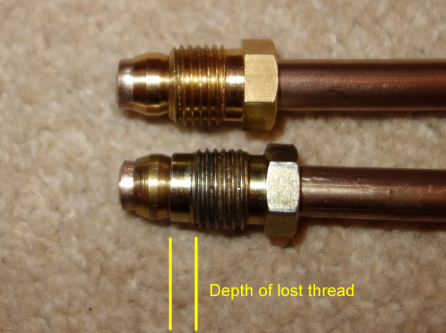 These earlier troubles had been caused by a combination of the pipe not being square onto the filter housing and the brass fitting supplied in the fuel line kit. The fitting had an un-threaded shoulder section which then only allowed a turn or two of thread to engage before it bottomed out on the olive. A replacement was found that was threaded to the end.
The vacuum tank needed to be removed to provide sufficient access to offer up the new pipe as it was bent into shape. I wasn’t happy with the original routing of this section of the fuel pipe, as the P-clip securing it to the bulkhead, pulled the pipe hard against the paintwork where there is an ‘X’ indentation in the toe-box.
| Original routing | Now routed higher on toe-box | Upturn no longer fouls bodywork |
|---|---|---|
 |
 |
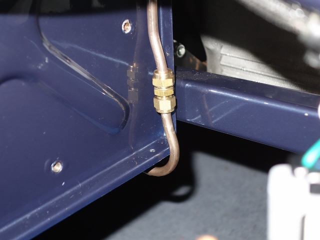 |
By inverting the P-clip, so the pipe was supported by the clip rather than being hung from it, the pipe is routed above the ‘X’. The other problem that was cured from my first pipe attempt was the length of the downward run to the union had been cut too short, causing the upturn bend to hit the bodywork.
Installing the fuel tank …. 4th time lucky!
I take my hat off to the original fuel tank fitters, who must have developed quite an efficient technique for getting the fuel tank in place on the production line. Although, with trails and tribulations I had trying to get the tank securely fastened, it was becoming a less daunting challenge with each fitting attempt. Perhaps there is some truth in the joke about E-Types being built up around the fuel tank!
First a few minor tasks were completed. The sump was checked for pinholes as it is prone to corrosion and fitting the missing metal fuel filter at the base of the pick-up pipe. The tank and surrounding bodywork was then covered with plenty of sheets and masking tape to try and minimise the damaging the paintwork.
| Fortunately sump was pinhole free | Pick-up pipe – now with filter |
|---|---|
 |
 |
The initial problem is the aperture of the boot space is less than the width of the seam-welded lip around the circumference of the tank. Tilting the front edge of the tank downwards doesn’t enable the lip at the rear to clear the flange for the boot boards.
There’s a gap in this flange where the boot lock attaches. So the only option I could see was to remove the lock and then tilt the tank sideways, feeding the lip through the gap vacated by the boot lock.
The most obvious approach was to raise the right side of the tank and feed it down to the left since the tank occupies the left side of the boot. However this first attempt failed as the sump attachment is proud of the base of the tank and comes into contact with the floor strengthening sections, halting progress.
So the opposite was attempted, feeding down to the right. The aim was then to shuffle the tank all the way across to the left once the flange had been cleared.
Yet just as it was nearing that point, it fouled somewhere else! It wasn’t immediately obvious what was causing the problem but eventually it was traced to the clip for the boot board. Fortunately it’s only riveted in place and could be removed.
| The offending boot board clip | Eventually the flange was cleared |
|---|---|
 |
 |
Finally the tank was below the flange and could be manoeuvred into position once the various filler and breather pipes were attached. The boot lid drainage pipe caused quite a bit of aggravation as it had a tendency to spring out of place and push the tank away from the mounting points.
| Corner bracket should have captive nut |
Breather tubes for later S2 tanks |
So near, yet so far |
|---|---|---|
 |
 |
 |
However, until now, I hadn’t noticed the replacement forward mounting bracket simply had a nut welded to it, rather than a captive nut within a cage. The lack of adjustability provided by a captive nut meant it was impossible to get the distance between the two leftmost mounting points to match those on the tank.
 The tank had to come out in order to enlarge the mounting hole in the tank by a couple of millimetres. Unfortunately I wasn’t able to rig up something to measure the difference in centre distances with any degree of accuracy. The tank was re-fitted but it was still a millimetre out, so it was back out for some more fettling.
This time it fitted! Well two of the three mounts did. The third bracket is moveable as it can slide in elongated holes and so would be doddle in comparison. How wrong could I be!
The original bracket had one stud missing and two of the other studs had lost most of their thread due to corrosion. It didn’t feel it was worth trying to salvage it as new ones are inexpensive. So I made the mistake of buying a reproduction bracket – not once but twice!
| Damage to original bracket | Neither repro brackets were usable |
|---|---|
 |
 |
The first wouldn’t fit because the studs were too far apart to mate with the holes in the bulkhead. To make matters worse, I only found this out after it was powder coated. The second was ordered from a different supplier. The studs were in the right place but much smaller diameter. However, as with the previous bracket, they both just had a nut welded in place rather than the captive nut.
This mount requires both lateral and fore/aft adjustability to have any chance of alignment with the bolt. Lateral adjustment is provided by the elongated holes for mounting the bracket. The movement of captive nut provides the fore and aft adjustment. Neither of the repro brackets were useable.
Its times like this that I do get frustrated with all the suppliers – it’s just lazy ‘that’ll do’ mentality and often it would be as hard to get wrong as it would right. Although I really should have spotted the differences when they were purchased. The original one will be repaired, which is what I ought to have done in the first place. Another lesson learnt!
Fuel Sender – stumped but fixed
For some reason the low fuel light on the dash wasn’t working, yet the fuel gauge was fine. The fault was traced back to the fuel sender unit, which has a removable cover plate. So it was easy to gain an understanding of how it worked to control both the fuel gauge and warning light.
| W & T terminal mechanisms | Low fuel light contact strip |
|---|---|
 |
 |
As would be expected, the unit uses a rheostat to vary the voltage drop across the fuel gauge and the warning light is simply a contact switch. However I hadn’t realised they were two completely separate circuits, sharing a common earth – the sender unit housing.
As the float arm rises and falls with changes in fuel levels, its pivot rotates through approximately 80 degrees. Two slider contact arms are attached to the pivot within the unit and therefore follow the same arc. They are also in contact with the sender housing and so are the electrical contact to earth.
Fuel Gauge
One of the sliders runs along the edge of tapered coil of resistance wire which is connected to the exterior T terminal. When the tank is full and the float is raised to its maximum, the full length of resistance wire lies between the slider and the T terminal – a total resistance of 196Ω.
When the tank is nearly empty and the float is at its lowest, the slider will have moved shortening the length of resistance wire between the two. At empty, the rheostat resistance is 18Ω. The fuel gauge is calibrated to display Full and Empty for these two resistance values.
Low Fuel Light
There’s a copper contact strip on the inside of the cover plate which has a small diagonal break in the copper so the two ends are electrically isolated from each other. The W terminal, connected to the gauge, makes permanent contact with one end.
When the tank is full the second slider arm is in contact with the other end of the strip and moves towards the W terminal contact as fuel is consumed. The slider eventually moves across the gap making electrical contact with the W-terminal, completing the path to earth and switching on the warning light.
I couldn’t work out why it wasn’t working. The multi-meter confirmed the internal connections were working correctly. Yet the switching wasn’t evident at the external spade connector. It didn’t make sense as a metal rivet connects the internals with the external spade terminal.
Checking with the multimeter confirmed that somehow the rivet and the external spade terminal were electrically isolated from each other. A dab of solder solved the problem but I still can’t fathom how they could not be in contact with each other.
Once it’s up and running, I’ll fill from empty to find out how many litres of fuel are in the tank when the light comes on.
The tank has since been filled from empty and it takes exactly 12 litres (2.6 gallons) before the warning light goes out. So there should be around a 50-55 miles range once the warning light comes on.
Wow, that is looking really nice Chris. You’ve done a spectacular job there. Well done. Dave