Apr 132015
 

Trimming wasn’t something I was looking forward to! My kit had been supplied by Suffolk & Turley. The only thing that appearred to be missing from the kits from all the various suppliers is any form of guidance, let alone detailed installation instructions!

It was very much a case of trial and error, never having trimmed a car before! So what follows is the approach that worked for me (and in some cases not!!).


A simple jigsaw puzzle!!

The kit consists of all the jute underlay, vinyl, Ambla, Hardura, vinyl covered panels and carpets. So one would assume it’s all fairly obvious how it should be installed. It’s the subtleties that are not explained! The trimming of the seats and central console were beyond my capability, so these had been supplied ready trimmed.

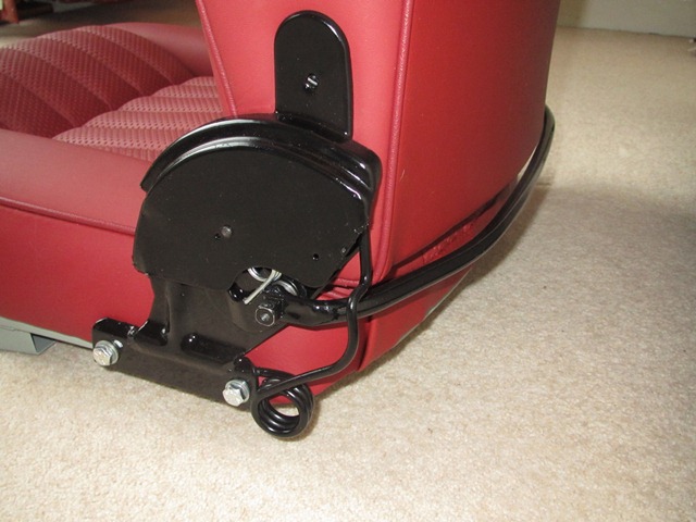
The initial focus was to get the car through an MOT and then do the interior trimming. However the decision to install boot-mounted inertia seat belts had put paid to that! They required most of the trim behind the seats to be fitted first.

The kit contained some 5mm open-cell foam underlay for the sills and rear wheel arches. The problem with this foam is that it isn’t very robust, losing its spring quite easily and disintegrating over time. I therefore decided to replace this with a denser closed-cell polyethylene foam, sold under the brand name Plastazote and available in a variety of densities and thicknesses.

As it’s denser, it won’t compress as much as the open-cell foam and so the edges would be more pronounced through the vinyl covering. I decided to purchase both 3mm and 5mm medium density sheets (Plastazote LD45) with a view to playing around chamfering the edges to get the finish I wanted. The decision was to use the thicker 5mm foam for the sills and wheel arches as it gives a softer, more luxurious feel. The lower rear bulkhead is normally just covered with Ambla (vinyl with an expandable knitted backing) but this would be covered with the 3mm foam first.

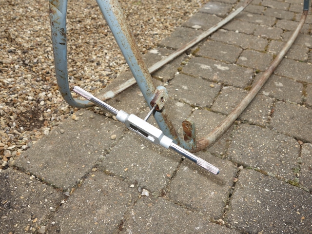
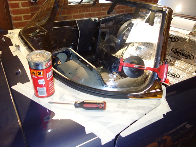
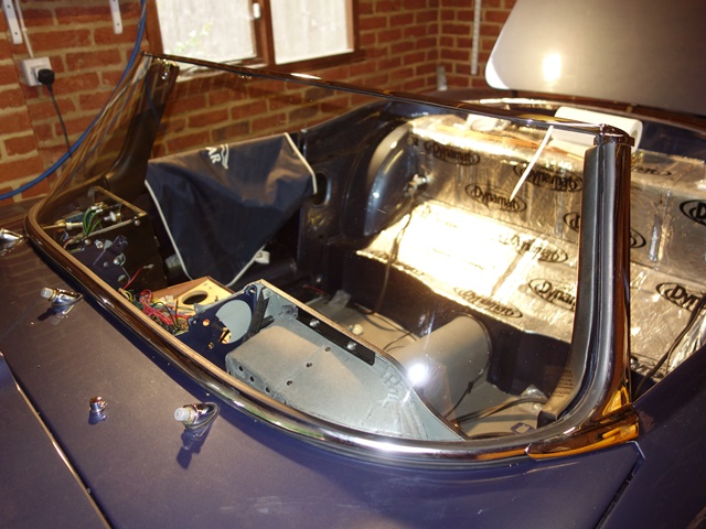
The trim covers recesses in the rear bulkhead and the wiring loom channels in the sills, which can become visible over time if the material pressed in. In an attempt to stop this, these areas were covered with reinforced cross weave tape. I also ran guide strings within the loom channel in case I need to run power to the rear of the car in future, eg for powering security/tracker devices.

Guide strings added – just in case! Then loom channels were taped over

Lower rear bulkhead
The 3mm foam was bonded to the rear bulkhead with a spray-on high temperature contact adhesive, purchased from Woolies Trim. It was more manageable to tackle it in two sections with the join above the transmission tunnel. Each section was then glued in three phases: the outer flat section, the concave area behind the seat and finally the small area around the transmission tunnel.

This approach allowed the non-glued section to be held against the bulkhead to make sure it was square across the full width before pressing the bonded area onto the bulkhead. The contact adhesive doesn’t allow a second attempt so it really does have to be right first time.

Each side was started at the sill end Next the concave section Foam in place … now the vinyl!!

I’d read other restoration websites covering the interior trimming, where they explained the vinyl should only be bonded to the perimeter of the foam underlay. So I followed this approach for gluing the Ambla to the rear bulkhead. Again I decided to tackle it in smaller manageable areas – the order as shown in the left photo below.

Areas and order of gluing the Ambla So far so good … section 1 bonded!

It was all going well up to section 3. To avoid wrinkles, the Ambla needs to be ever so slightly stretched as it is bonded to the foam. However, when the lower area (4) of the concave section was glued to the foam, the un-bonded area between (3) and (4) pulled away from the foam, as the Ambla contracted.

I tried to pull the Ambla away from the foam as soon as I realised but this just resulted in the latter being ripped apart. Aaaargh! Both the Ambla and foam were ruined. It took many messy hours to remove the remains of the foam, back to the painted bulkhead so I could start all over again.

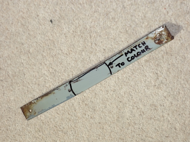
The revised plan was to bond the whole contact area between the foam and Ambla. This time the process followed the sequence of bonding the foam, although in reverse – working from the transmission tunnel out to the sill, as the whole area needs to be covered by a single piece of material.

Revised area and order of gluing Bonding area limited by matching masking
The second attempt worked well The lower bulkhead trimming completed!

The main difficulty with the rear bulkhead Ambla is it needs to cover the body looms to the rear lights, fuel pump and tank sender. The sills have a recess to hide the looms but they stop just before the end of the sills so there is no tidy solution.

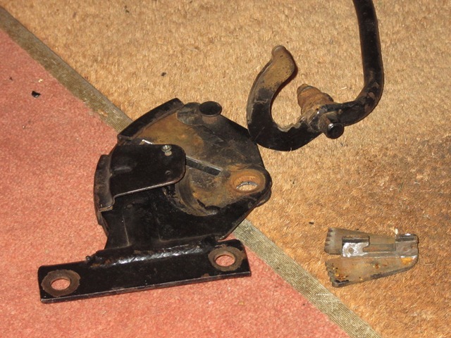
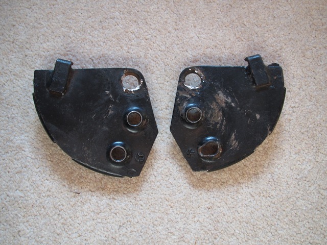
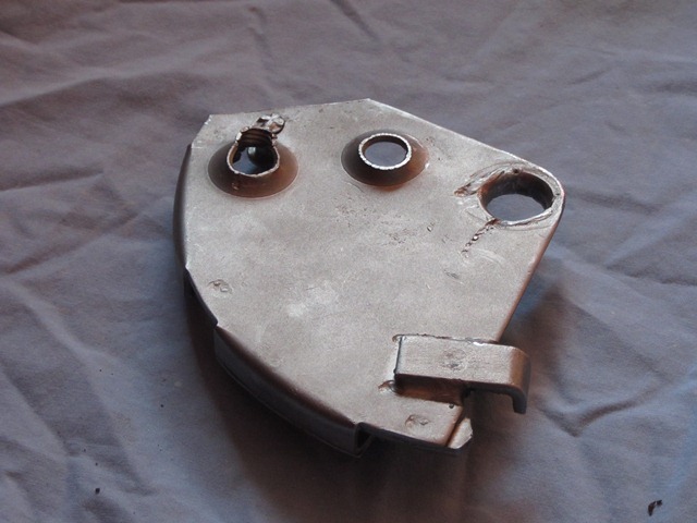
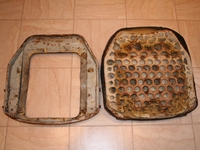
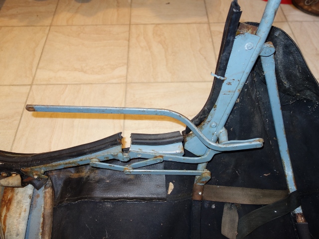
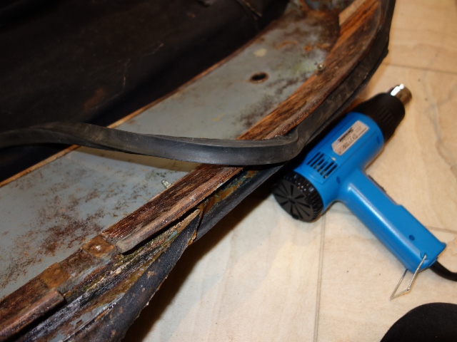
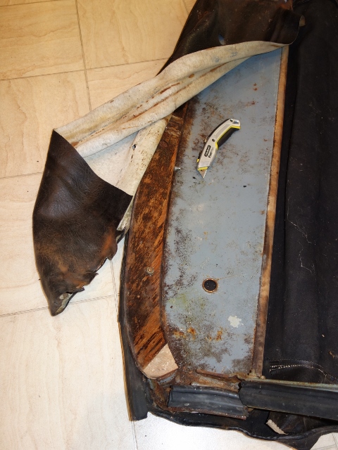
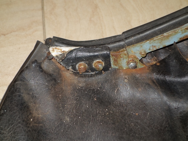
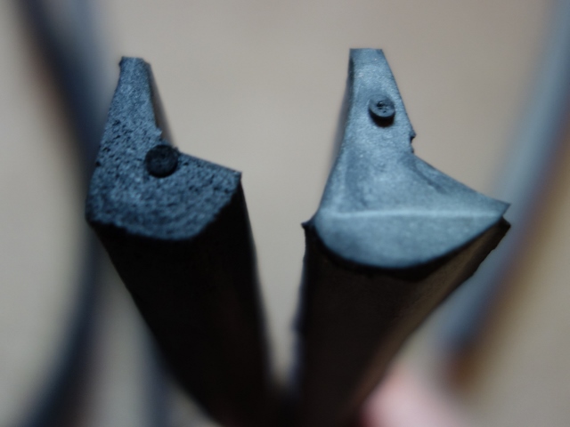
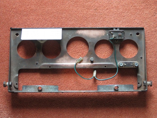
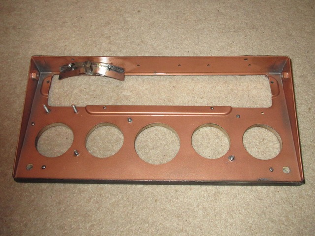
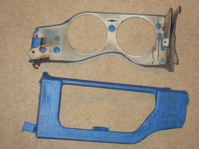
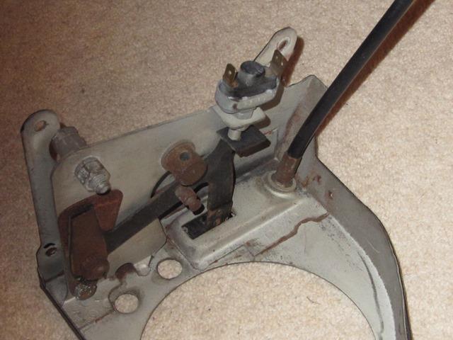
Sometime later, I was trying to find the best method of hiding the wiring looms as they travel around the lower edges of the wheel arches before entering the boot space. I couldn’t disguise the looms under the Hardura trim covering the rear bulkhead and so dug out the remains of the original trim to see if I could get any clues.

The (non-vertical) areas should first be covered by a layer of jute before the Hardura goes down and the excess bulkhead Ambla bonded over the jute. The trim kit didn’t include jute for this area, and indeed some for the rear face of the boot, so it was easily missed.

Although I had already fitted Dynamat sound insulation, it is much thinner than the original jute layer, and therefore not able to disguise the looms. The solution will be to fit some 1/4″ Dynaliner, with suitable channels left for the looms. The down side is that the excess Ambla will have to be lifted and re-bonded over the Dynaliner.
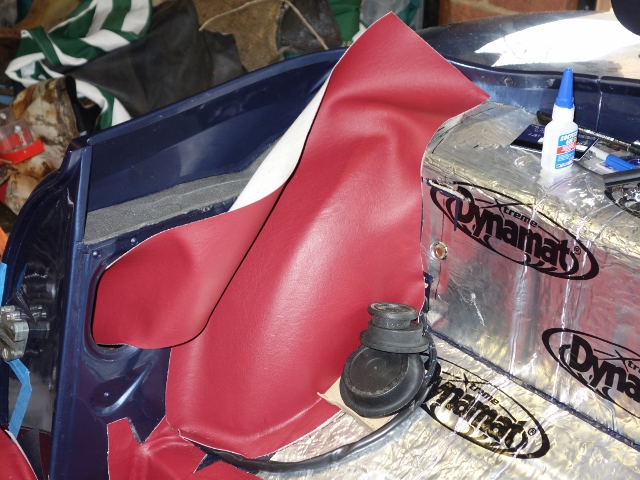
The Ambla was bonded over the looms Different bonding was needed against the Koolmat

The other issue was trying to bond the vinyl and Ambla to the silicone Koolmat, used to insulate the cabin from heat soak from the engine bay. I’d previously tested various adhesives such as contact adhesive and silicone RTV adhesive. Since then I’d found that Loctite produce a silicone surface preparation fluid (Loctite 770) which enables the ‘superglue’ Cyanoacrylate family of adhesives to bond to it. The combination of Loctite 770 & Loctite 406 superglue provided a very good bond and was used to secure the overlapping vinyl and Ambla to the grey Koolmat.

Sills
The 5mm foam and vinyl covering the sills were fitted, again in stages, working inwards from the outer edge. The foam was cut so there was a 1cm gap to where the sill meets the A & B-posts and also the floor. This was to provide a bare area of sill for the vinyl to securely bonded to.

For the gap to the sill edge, the chrome finisher was offered up. A gap of approx. 13mm would avoid foam being trapped under the chrome trim as it’s a fairly tight fit at the best of times. I didn’t want foam underneath to make things worse. The vinyl wraps around the sill lip and should be held in place by a number of metal clips.

A gap was left between the foam & sill edge First stage of bonding the foam underlay

I had a trial fitting of the clips using some scrap vinyl to see if they would stretch the vinyl as they were pressed on. No matter what I tried, I couldn’t get the clips on. I mentioned this to Suffolk & Turley when I was up discussing the hood – they don’t bother with the clips! They just run a bead of silicone RTV adhesive in the chrome finisher, wedging it in place while it cures. A tip I will be using once the sill door rubber is in place.

The approach of applying adhesive to the whole foam/vinyl contact area worked well with the rear bulkhead and so would be repeated for both the sills and rear wheel arches.

The vinyl was started by just bonding the 13mm strip at the sill’s edge. The aim was to anchor the vinyl in place as it would require cutting to shape as it was applied. The spray adhesive doesn’t give any room for adjustment once the two surfaces have been pressed together. So I thought it best to use the brush on Alfabond AF178 for gluing the sill edge and then pressing on the chrome finisher to hold it all in place, while it set.

Marking out the excess vinyl Excess can cause door rubber problems Bonding underneath the sill edge

Adhesive wasn’t applied to the underside of the sill edge, which allowed the vinyl to be pulled out to cut off any excess before being bonded. Too much excess can lead to problems fitting the sill door rubbers later on.

The edge of the vinyl is visible for a few inches; forward from the door opening to the A-post; reward to the B-post and 2-3″ along the outer face of the B-post (before it is hidden by a vinyl covered panel). The vinyl was doubled over to keep these edges neat and tidy.

The visible edges were doubled over to keep them neat

As the vinyl doesn’t stretch like the Ambla, a number of cuts were needed as it turns down towards the sill. There were a number of scares along the way where I didn’t think it was as smooth as it could be. The on-the-fly remedies often made matters worse. Fortunately the foam regained its shape overnight!

Again, bonding was done in stages Trimming around floor strengthener Sill vinyl almost completed

Overall I was quite pleased with the results. If it were to repeated, I would probably only leave a 5mm gap between the foam and the A & B-posts.

Rear Wheel Arches
The trimming of the rear wheel arches appeared to be much trickier due to the double curvature …. and so it would prove to be!! The pre-cut material has a very odd shape as it covers the wheel arch and a flat section underneath the hood mounting brackets.

Area covered by the wheel arch Ambla …. hence the odd shape of the trim provided

Numerous dry runs were done before deciding on how best to tackle it. Initially I started with bonding an outer section of the wheel arch, and the working down towards the lower rear corner. It soon became apparent that this wasn’t the way to go.

It left too much foam being pressed into an ever decreasing area, causing ruffling. Fortunately it was possible to cut out a section of excess foam and make a joint that would be invisible through the Ambla. This wouldn’t be an option when the Ambla is fitted.

Initial area bonded on 1st attempt Resulting in section cut out of foam

For the Ambla, it was decided that it would be best to glue a 2” strip down the shoulder of the wheel arch but stretching it as it went down. The reasoning was it would therefore reduce the excess material in the corner of the wheel arch.

Bonding this area first caused numerous problems!

Unfortunately this didn’t prove to be too successful and it was a real fight to get the lower edge glued without it puckering up along the join between the wheel arch and the bulkhead. Occasionally some Heath Robinson techniques were needed to weigh down the Ambla until the adhesive had dried. I shouldn’t have been surprised as it was not too dissimilar to the approach for the foam. A re-think was required for the other wheel arch!

Weighing down the edges to stop it lifting Bonding the lower edge worked better

The other tricky area was where it transitions between the curved wheel arch and the flat section. The Ambla just had to be stretched in the right direction to get a smooth finish.

For the second wheel arch, a 1.5” strip was glued along the lower edge. The foam could then be stretched up to the corner where it meets the top of the rear bulkhead. This ensures the Ambla is ripple free as it is being stretched over the curvature of the wheel arch. Initially this appeared to be a much better approach although it simply transferred the problems encountered later on to another area. The conclusion is that the wheel arches are just difficult to trim.


An Ambla covered wheel arch. Phew!

The trimming of the vinyl and Ambla was quite tricky and took over two weeks to complete, mainly due to putting off tackling the difficult areas and procrastinating too much! It would have been almost impossible to complete without the assistance of my trusty helper who patiently held the material up, while it was being smoothed into place and took the brunt of frustrations when things didn’t go as planned!

In hindsight, I wish I’d have bought shares in 3M with the amount of blue masking tape I ploughed through!!

Hardura and carpet fitting will be covered in Part 2 ….

Mar 252015
 

New hood pivot bolts

The removal of the hood many years ago had been problematic to say the least. The threaded section of the pivot bolts is a much smaller diameter than the unthreaded section, which the hood sticks pivot around. The bolts wouldn’t come free even after applying penetrating fluid and adding an extension piece onto the ratchet handle. The force being applied was more likely to shear the threaded section, so I stopped to have a re-think.

However the problem wasn’t that the threaded sections had seized within the bracket’s captive nuts as I had thought. Small holes are provided in hood sticks for oiling the pivot joints. Unfortunately it’s doubtful they had ever been troubled during routing maintenance!

The result – the whole pivot joint had rusted, fusing the bolt to the hole in the frame. The hood no longer pivoted on the bolts. The bolts and frame just rotated in unison in the mounting brackets, as the hood was raised and lowered. The only way I could then remove the hood was complete with mounting brackets.

I couldn’t believe how solidly they had rusted in place. In a foolish fit of pique, I ground away the heads of the bolts, which were looking decidedly rounded by this time. Cutting through the threaded sections to finally free the hood from the brackets. The whole hood was left, as is, until now so I still had to overcome the issue of removing the remains of the bolts.

The remaining sections of the bolts wouldn’t budge even after soaking in Plus Gas penetrating fluid for several weeks, applying heat, attempting to press them out in a vice and, in a Cleese-esque manner, giving them a good thrashing with a club hammer!

The hood needed a full overhaul Every hood fixture was heavily rusted First, removal of the old canvas

The plan is to have the hood professionally fitted by Suffolk & Turley. Even though they will happily undertake all the work, including the renovation of the frame, I wanted to do as much as possible myself. So I set about removing the canvas and dismantling the frame into its components on order to have them powder coated.

First, the canvas was detached from the rear of the frame – by removing the side chrome trims, which clamp the canvas rearward of the drop glass and unpicking the webbing attaching it to the frame sticks. Removing the hollow, square-sectioned rubber seal, which makes the seal against the top of the windscreen, reveals the canvas and vinyl edges in the channel underneath. The canvas and vinyl could then be pealed off the canopy, while applying heat to soften the adhesive.

Main head/cantrail brackets attached to frame Bonded edge of canvas/vinyl under screen seal Vinyl removed revealing wood canopy bows

The detaching the cantrail and main head brackets also proved troublesome. The removal of the pivot bolt remains was soon joined by the need to remove half a dozen screw stubs. Some of the screws fixing the main head/cantrail brackets and hood clamps had sheared or had to be drilled out. Their slotted heads had become too damaged by attempts to unscrew them.

Latch covering trim under two canopy mounting bolts Softening old adhesive with white spirit

The pivot bolts were removed by drilling a pilot hole down the centre of the bolt. It was more important to keep the pilot hole square on to the bolt than ensure it was precisely centred on the bolt. Progressively larger drill bits were used to enlarge the hole until a line of rust could just be seen running down the length of the hole. A pointed drift was then used to collapse the perimeter of the bolt inwards allowing the bolt remains to be pushed out.

The same approach was followed for the screw remains in the hood sticks. Although this time it was essential that the drill bit was centred on the bolt so the thread wasn’t damaged. They were then re-tapped to reinstate the thread.

Initially the canopy didn’t look too bad but it had clearly been worked on before as the whole frame had been hand-painted a light blue rather than the original light grey. The forward wood bow had a small section missing and it had started to delaminate. The edge of leading edge had rusted away along the entire length of the canopy although it should just be a matter of welding in some new metal.

The leading edge has rusted away The wood bow was also delaminating Re-tapping the frame after drilling out screw stubs

A second opinion was needed so it was taken up to Suffolk & Turley in Nuneaton. Their evaluation was not good, enquiring whether I’d found in it a canal! In addition to the problems I’d spotted, they pointed out that the lip where the two outer skins meet had been cut away at one end. It should be proud of the wooden bow by approx. 2cm as it forms the upper part of the channel for the rubber seal. Also, the front 6 inches across the full width of the canopy was largely filler.

Their preference is to re-use original parts rather than replace. The replacement wood bows are available but the quality is not great and it takes some work to get them to fit. Even so, their verdict was it wouldn’t be cost effective to repair the metal canopy and the front wood bow was unlikely to survive its removal. Only the rear wood bow was worth saving, as these are no longer available.

It was a long way to travel to learn that the canopy was junk and I was now resigned to inevitable fleecing that was coming my way! Both for a new metal canopy and a wood bow, which I believe is north of £300 from SNG Barratt!

As luck would have it Martin Robey had one S2 canopy left in stock so it was secured on the spot. A week or so later it hadn’t turned up so I gave them a call. It was ‘virtually’ in stock … they just had to make it first! Two months later it finally arrived.

In the meantime I’d found a Czechoslovakian subsidiary of the German company Slavik, which made all the wooden components for earlier Jaguars, and at a very reasonable cost of £75 for the wood bow. They were making a trip to the UK a few weeks later and suggested sorting out the payment and shipping once over here. Needless to say, I didn’t hear from them so I presume they forgot to bring it and I got no response from follow up emails.

Trial fitting the rear bow to the new canopy Replacement canopy wood bow

Finally a piece of luck, a wood bow appeared on eBay. I’d lost so much time waiting for parts, I contacted the seller and agreed a private sale, rather than wait until the end of the auction. A trial fit of the bow with the new Robey canopy confirmed it will need a fair amount of fettling to get it to fit.

Now I had all the components, it was off to Nationwide Coatings”to have them powder coated in BS381C-694 ‘Dove Grey’. The advice from the E-Type forum was that this was the correct/nearest colour match. Typical …. the powder coating manufacturers no longer supply powder covering the old BS381C range!


Original paint allowed a colour match

Traditional paints do not adhere to powder coating. However new paints have been produced specifically for this purpose. So they recommended powder coating the hood components to the nearest light grey colour available and then over-coating with a colour-matched paint. A couple of parts had hidden surfaces that missed being hand painted in blue so they will be used to get an exact match to the original colour. The powder coating should provide the durability while maintaining the correct colour.

My aim had been to get the car ready for a trip to the Monaco Grand Prix at the end of May. This is now looking to be a very long shot, having lost two months waiting to just trial fit the hood. Also, in a nod to practicality, I’d decided to fit inertia seat belts rather than static seat belts. These have been on order since the New Year and there’s still no confirmed delivery date. The fitting 3-point Seat belts became mandatory from 1968, so I won’t be able to get an MOT until they do.

Jan 092015
 

Once it became clear that the September target for obtaining an MOT would be missed (albeit with a stripped out interior), the pressure was off. With the cold, dark days of winter setting in, holidays in warmer climes became preferable to working on the car and so the momentum lost.

The new target being the spring, once the last traces of road salt have gone. Just in time to sort out any niggles and put a few miles on the clock … before a mooted caper to the Monaco Grand Prix. It would be a fitting inaugural tour! Apart from the lack of trim, the car appears to be nearing completion. However looks are deceiving and the ‘To Do’ list is still alarmingly long. So I’ve got to get cracking!

I’ve not been looking forward to installing the trim as it’s notoriously fiddly and something I’ve not tackled before. It’s the part everyone sees so it has to be done well. After all the effort so far, a poor job would not suffice! Further procrastination was required under the guise of trim planning ….

I settled on the following order of events:

  • Door A-post rubber seals
  • Fit and align the window frames and drop glass
  • Door B-post seals (the sill seals will have to wait until after the sill vinyl has been fitted
  • Trial fit hood frame to ensure the glass seals against the hood’s cantrail rubber seals
  • Vinyl trimming – sills, lower rear bulkhead and wheel arches
  • Sill seals and chrome finishers
  • Underfelts followed by hardura panels, vinyl covered finishing panels and carpets
  • Centre console and radio panel
  • Under-dash felts, hardura and cards
  • Install the seats!
  • Install inertia seat belts in the boot space

I’ve decided it was best to leave the fitting of the hood and tonneau cover to the experts, Suffolk & Turley, who supplied the trim kit. Finally, once the car is returned, I’ll fit the door cards and boot trim.

Door Seals
New door rubbers were obtained from SNG Barratt. However I wasn’t happy with the A-post and sill seals as, not only were their cross-section profiles noticeably larger than the originals, they were made of a much harder foam rubber.

Other owners have posted issues with poor quality seals leading to ill-fitting doors which need slamming just to get the door to latch. The general consensus on the E-Type forum is to source all the rubber seals from COH Baines so a new set of door seals was duly ordered. I would thoroughly recommend doing so as they are much closer to the originals and made from a softer foam. I believe SNG Barratt have subsequently started to source many of their seals from COH Baines.

Profile comparison of sill seals Darker Baines rubber is thinner & softer

Hutsons had pre-fitted the doors to the bodyshell, so the door strikers and locks were correctly set and panel gaps were all spot on. However the fitting of the A-post seal requires the door to be removed to provide sufficient access. So the outline of the door hinge was marked out with masking tape to aid re-fitting.

Position of hinge marked with masking tape Tape was also used to trial fit the seals

Before removing the door, the A-post seal was trial fitted by taping it in place. Adjustments were made until the door could be closed easily without too much resistance. Some trimming of the seal was needed where it has a protrusion at the base of the A-post.

Initially I had cut the seal exactly to length but the door felt a little hard to close. It is rather subjective at this stage, without the resistance of the other seals. I wanted to keep the additional force needed to compress the A-post rubber to a minimum.

Being nearest the hinge, it requires considerably less force to compress this seal so any noticeable increase now would be magnified once the B-post seal is fitted. Being made of a softer foam allowed it to be cut marginally shorter and then stretched to reduce its cross-section, therefore reducing the resistance.

Once I was happy with the fit, it was time to remove the door to bond the seal in place with the Alphabond AF178 high temperature contact adhesive I’d used for the Koolmat.

The advice for getting the best bond and avoid the seals pulling away is to clean them with methylated spirit to remove any traces of the mould release agents and roughen the surface to be bonded with sandpaper. The contact adhesive should then be applied in three steps:

1. Apply a layer to the rubber seal and leave until tacky
2. Apply a layer to the seal channel and again leave until tacky
3. Apply a second layer to the rubber seal, once the first layer has gone tacky, and when this second layer becomes tacky, push the seal into the channel

I found it easier to tackle the A-post seals in two stages: first from the triangular section at the base of the A-post up to the top of the A-post and then the lower section down to the sill. For the lower section, I inserted a small diameter rubber hose into the gap in the rubber seal before securing it with masking tape. This worked really well in holding the rubber against the sides of the channel until the adhesive had dried.

Top half of A-post bonded first Once dried, the lower half was tackled

Everything was held in place for 24 hours with masking tape and then any excess adhesive removed. First softened with a cloth soaked in white spirit and then carefully wiped away. There were some areas where the adhesive had lifted away from the paint work so these required some touching up and re-bonding. Another tip I was given was to use Dum-Dum style body putty to fill any small holes or gaps.

Previous hanging of doors had been a frustrating and fiddly experience so I only wanted to do it once. The weight of the various internal door mechanisms is not insignificant. So I wanted to have the doors at their full weight before setting all the panel gaps, thus avoiding the risk of them dropping by adding them later.

The doors were refitted to their marked positions and the door internals completed (see below). Only then could the fine adjustments be made to get the panel gaps right. As would be expected, the doors had dropped slightly under the additional weight of the internal mechanisms and so the hinge position within the door had to be adjusted to compensate. A trolley jack was used in place of a suitable assistant to support the door while fine tuning the panel gaps.

Solo door hanging Bonding the bonnet landing seal

I could then move on to the B-post seals, which were tackled in the same manner as the A-post seals. Although these were fitted in one go and needed the bonded edge to be sanded down in places to enable the door to close without undue force. Hopefully, once the final sill seals are added, the doors will still shut easily. If not, it might be a case of re-doing all the rubber seals and re-hanging the doors!

Finally the bonnet landing rubber was bonded in place while the adhesive was out. It was also more manageable by tackling this in two stages.

Door internals, window frames and drop glass
The next task was to complete the fitting of the door internals and drop glass. The initial fitting of the frames produced very different results. The frame on the driver’s side was fairly close and possibly needed a shim added at the rear to bring the leading edge parallel with the A-post.

The passenger side was way off! The leading edge was angling away from the A-post, by approx. 6-7mm at the top, and this was with the rear of the frame raised by two thick shims. Something was wrong!

The driver’s side frame was fairly close However it wasn’t the case for the passenger side!

Suspicion fell on the geometry of the window frame, which had been re-chromed. The re-chroming process involves polishing the underlying plating before the chrome layer is applied. This can cause distortion due a combination of the pressure applied to polish the part and the resulting heat that is generated.

Sure enough, when I tried to fit the drop glass, the regulator channel the glass sits in would not fit into the frame. It was too long, front to rear. I then used the driver side drop glass as a comparison – it’s length fitted fine! Much head scratching ensued … it must be the reproduction regulator channel.


Difference in angles of
rear regulator channels!

Overlaying the two revealed the problem. The angle of the rear of the regulator channel was way off on the passenger side. After much cursing of reproduction parts (that enable us to keep these cars on the road!), I set about removing the glass from the regulator channel. Gentle prising with a screwdriver would only end in tears as the rubber grips the glass very well.

Fortunately a small amount of penetrating oil worked wonders and the glass came out surprisingly easily. The rear edge was bent into the correct alignment and the glass and rubber re-fitted. Longitudinally it now fitted the frame.

Alas the same couldn’t be said for the width. The leading edge of the glass sits in a flock lined rubber channel. While at the rear, the short trailing edge of the regulator channel sides metal on metal in the window frame. The width of the repro ones were too wide.

Both regulator channels required a fair amount of filing to reduce their width so they slid easily within their channels. It was only once I started filing that I realised the rear section was made of brass but had then been zinc plated. When I had first fitted them I had cursed the fact that the reproduction parts hadn’t used brass, as in the originals!

Both regulator channels needed filing Regulator channel were polish to reduce friction

Once they slid easily within their channels, I decided to polish both the regulator channels and the window frames to reduce future binding problems. Some Shin-Etsu Silicone Grease will be applied to the seals and mechanisms before the door cards are fitted.

Attention returned to the passenger side window frame as the glass did not slide cleanly all the way down. The reason was found to be cause by the chromed leading edge of the window frame being bent out of alignment – both rearwards and outwards! Fortunately gentle persuasion allowed it to be re-bent close to its original shape.


The width of the channel
allows the glass to rattle

I thought this would be the end of my window woes. How wrong could I be! The flock lined front channel comes in two sizes for 4.75mm and 6mm glass. I had the latter but, with the glass being a little shy of 5mm, it allows the window to rattle within the channel. However, the smaller size would cause binding issues.

At this point I chuckled as I’d been in correspondence with the Jacksons whose E-Type refurbishment exploits have been covered in the E-type magazine. They had already experienced almost identical restoration issues, not just in the fitting the drop glass! But now I think I understood the issues they had encountered with the flock lined channel.

I also purchased some lengths of thin rubber strips to pack one side of channel in the window frame before inserting the flock lined rubber alongside. This closes the channel slightly to guide the glass without causing it to bind or allowing it to rattle.

Building up the door innards
The first task was to fit the door handles and then set the gap between the push button plunger and the lock/latch striker lever to 1/32”. This should ensure that the latch is fully released when the push button is pressed. Adjustments were made by slackening the lock nut on the plunger, adjusting the setscrew and then nipping up the lock nut.

Setting the plunger-latch gap Allen key fixing lever position Setting the handle/lock link

The fitting of the link between the door handle lever and lock requires the lever to be fixed in position. Aligning a hole in the lever with a hole in the rear casing allows a small Allen key to be inserted to lock the position. The link is then fixed to the handle lever. Its lower end has three overlapping, fittings holes and it is simply a matter of picking the best fit to the lock lever.

The regulator springs had been removed prior to the regulators being plated and were showing signs of rusting. They were shot blasted and blackened with a four stage process supplied by Caswell UK. The process only takes approximately 30 minutes but the final stage requires the component to be dipped in oil and then left to dry overnight. I’m not convinced how durable this finish will be and its ability to stop future rusting so it will be packed with grease prior to fitting the door cards.

Regulator springs prior to blackening Spring after blackening and dipping in oil Regulator wound to refit spring

With the springs fitted, the regulator could be inserted from above, followed by the two brackets to secure the bottom of the window frame to the base of the door. These brackets are moveable on their mounting stud so the lateral position of the top of the drop glass can be adjusted. These were only hand-tightened as they will need adjusting when the hood frame is trial fitted.

Regulator was fed in from above Rear window bracket Front bracket is shorter

I found it easiest to insert the window frame by first tilting it forward and inwards at the top until the front stud has cleared the door frame. It was then secured at the top in three places, where two screws pass through the window frame and door frame into a thin plate below. Shims can be added as required between the window frame and door frame to either raise the whole frame or tilt it so the frames leading edge is parallel with the A-post.

(Although when I mentioned this to E-type expert Ken Verity, he suggested the need to tilt the frame with shims would suggest the frame might not be 100% true. This may cause window binding problems so needs to be checked before continuing. Distortion is typically caused by people use the glass or frame to pull themselves from the car.)

Clearing the front stud Fixing for top of the window frame Regulator fitted and at full height

The external glass weather strip needed to be clipped onto the door skin before inserting the drop glass because there wouldn’t be sufficient access once the glass was in place. (Update – I was jumping the gun here and had to remove it! I had forgotten to fit the chrome door flash so had incorrectly assumed the weather strip was attached to the lip of the door skin. I think it needs to be clipped to the lip of the chrome flash!) The window regulator needs to be raised to its maximum height in order to engage it with the drop glass channel.

Engaging drop glass with regulator Almost there – drop glass fitted Door remote control attaches to lock

Next is the door remote control. Its link arm is attached to the door lock to enable the door to be opened by the interior lever. A wavy washer is fitted between the lock and the link arm to take up the free play. The square nuts fitted in the regulator channels set the maximum height of the windows but these will wait until the trial fitting of the hood.

The doors were also fitted with a bracket that had a semi-circular foam section bonded to it. This is to dampen vibrations in the remote control link arm. Unfortunately these were missing on my car but once again RM & J Smith came to the rescue for obscure, missing parts. They had a pair of original brackets that would need tidying up and the foam replacing.

Finding suitable replacement foam was not an easy task! Eventually I found Seals+Direct who offered a 1” diameter 1/2 round cord of expanded Neoprene (part ENHC94) which was ideal. Strips were bonded to the brackets with the Alfabond AF178 contact adhesive.

The small aluminium seal blocks need to be fitted to the trailing edge of the doors before the door rubbers are trial fitted because these compress the upper part of the B-post seal.

Bonding new rubber Damping brackets fitted Finally the sealing blocks

The last check was to ensure the height of the door frames against the A-post was even on both sides. The driver side was flush with the A-post cap while the passenger side was 1/8” lower. An equivalent depth of shims was added under the window frame edge to bring the frame up to the same level.

Driver’s frame flush with A-post Passenger side was 1/8” lower!

What should have taken a day or two ended up taking well over a week! Next will be the refurbishing of the hood frame ….

Update: a recent post in the ‘factory fit’ thread on the E-Type forum identified that the chrome bracket for mounting a hard top is secured at the top by a 12-28UNF cheese head screw. This screw passes through the channel for the B-post seal into the rear of the chrome bracket (circled in red below). Therefore the seal needs to be fitted after bracket and the bracket is fitted after the interior trim.

I will therefore have to undo my fine work and detach the top 3″ or so, by softening the contact adhesive with white spirit, and re-attach once the interior trim is completed.

Hard top securing bracket Securing screw behind B-post seal

Images courtesy of E-Type Forum

May 202014
 

The fitting of the windscreen was one of those tasks that I thought would be best left to a professional. One of the forum members had given a good feedback when their screen was installed by Howard of Merlin Motorscreens, based in Surrey.

Unfortunately I couldn’t arrange economic transportation of the rolling chassis to their workshop so it would have to be done in situ. As each car is different, I was warned that the installation may need to span over two days and that he may need to use his own supply of the rubber seals, depending on the quality of the SNG seals.

My only contribution to the whole process was to periodically returning to monitor progress and take a few photos of the various stages. On the positive side the SNG seals were useable. The whole area was protected with a generous covering of masking tape, the seals quickly trimmed to length and fitted to the windscreen flange using a bonding sealant.

In no time at all, the rubber seal had been lubricated with a soapy detergent allowing the screen to be eased into position from one side. A screwdriver was then used to get the final edge of the screen correctly seated into the seal. The next task was to tape the packing rubber strip to the top edge of the screen which sits between the screen and the top chrome finisher.

Windscreen slotted into rubber seal Taping the rubber strip Top chrome tapped into position

Re-chroming the top finisher can lead to distortion problems due to the heat created by the polishing process. Luckily my now banana shaped chrome finisher wasn’t too bad and he managed to tap it home with a rubber mallet.

At this stage you get the impression that the job is almost complete, but there was a lot more fiddly bits to do. There was much trial fitting of the A-post caps and chrome finisher to determine if and where additional packing rubber was required. The cavity under the rubber seal can be generous in places so additional rubber is pushed into these areas to avoid the screen dropping away from A-post caps later on.

Trial fitting A-post chrome Clamping the bonded chrome Completed A-post chrome

A beading strip could now be inserted into the rubber seal. Its purpose is to push the external side of the seal hard against the windscreen and mounting flange, locking the screen in position.

The chrome finisher, running along the base of the screen to conceal the beading, slides into slots moulded in the screen seal. Although contact adhesive is also needed to keep it in place in the long term.

The A-post chromes are also bonded into place although they are also fixed by screws along their rear edge and slotted under the A-post cap at the top. The interior trim also slots under the cap and therefore needs to be fitted at the same time. The bottom of the interior trims are secured by the same clips used to fix the door cards.

This leads to the logistics conundrum of what should be fitted first …. the final adjusting of the wiper linkages needs the windscreen in but the dash top off, to provide access the linkages. Putting the windscreen in, included the fitting of the A-post trims. However with the A-post trims in situ, it’s then not possible to fit the dash top!!

All that remained was to trim back the top rubber strip inside and out and remove any excess adhesive with white spirits. From start to finish it took just over 5 hours. If anyone in the South East is looking for their screen to be fitted, I would thoroughly recommend contacting Merlin Motorscreens.

Completed screen Interior A-post trim
Apr 292014
 

Following standard practice, most of the external trim was trial fitted as part of the preparation of the bodyshell. This enabled the bumpers and/or bodywork to be fettled to ensure a perfect, even gap to the bodywork. Once completed, the bodyshell was passed on to the paint shop and the chrome parts sent off for re-chroming.

The exception was the rear bumpers which sadly had to be replaced. The car had obviously had a minor rear-end shunt that had resulted in a crease in the middle bumper section and the outer sections distorted beyond repair. Hutsons had trial fitted the new bumper sections, which they’d sourced from SNG Barratt.

One of the reported problems with the reproduction bumpers is that the chrome plating is generally thinner and not of the same quality as the originals. Even so, when the painted bodyshell and rear bumper were delivered, I wasn’t expecting to find the inside faces to be showing signs of rust!

I wasn’t too impressed as this really should have been spotted when they were being trial fitted and rejected. The dilemma now was that these fitted the painted bodyshell perfectly which may not be the case if I got Hutsons to replace them.

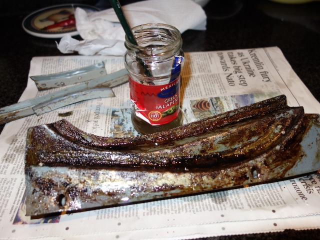
The intention had always been to paint the inside surfaces to provide better protection from the elements. So I decided to keep the new, rusty rear bumpers.

Meanwhile the remaining chrome trim had been dropped off to ACF Howell, who had been recommended. At the time, I felt reassured seeing many of the recognised Jaguar specialists listed on their white board of work in progress.

When they were returned, they’d already given the insides of the front bumpers and overriders a light coat of silver paint. However, on closer inspection, the paint was lifting in places on the overriders. Rather worryingly the cause was found to be more rust! So everything would be given a good coating of the silver Epoxy-Mastic 121 that I’d used on the front suspension.

Once all the chrome surfaces had been masked, the rusty areas of the ‘new’ bumper were bead blasted and the insides given three generous coats of epoxy-mastic followed by a couple of coats of Dinitrol 4010 hard wax. Hopefully this should be sufficient overkill to keep corrosion at bay for a while!

Mar 272014
 

At some stage the previous owner had fitted an aftermarket 16″ Moto-lita steering wheel. Even though there was absolutely nothing wrong with it, I was toying with the idea of swapping for either a 15″ or possibly even a 14″ wheel, which a number of owners fit to increase the leg room. The steering would also be more direct with the smaller wheels with the obvious trade off being progressively heavier steering around town and parking.

Still, the unanswered question was, how much heavier would the steering become? Finally I decided to stick with my approach of keeping to the standard specification and only making changes once I’d driven it for a while. However, while I was dithering on what to do, I got distracted by an original rather ropey 16″ wheel on eBay. The wood had dried and split beyond repair so it needed to be re-rimmed … as though I didn’t have enough to be getting on with already!

16″ Moto-lita wheel Original wheel from eBay Splits in the wooden rim

The splits in the rim ran almost for the full circumference which made its removal very straight forward. Fortunately there are a couple of people offering replacement mahogany rim kits. The new rims are ever so slightly thicker and so will have the benefit of being more rigid.

Unlike the very early E-Type steering wheels, the aluminium ring is entirely enclosed, in a groove cut into the bottom half of the wooden rim. The two halves are then bonded and a gloss varnish applied to the wood.

Splits made removal a doddle Aluminium section freed Replacement rim kit

The Series 2 steering wheels changed from the polished finished to avoid the reflective surface. I wasn’t convinced I’d be able to get a satisfactory brushed effect and so have decided to go for a polished finish.

The numerous scratches and light pitting in the aluminium section were too deep to be removed by polishing alone. So it was necessary to lightly sand it to remove the blemishes, prior to polishing. Initially 600-grit paper was used and then 800-grit until the scratches had disappeared. It was rather worrying at the start as you tend to question whether you’re making it worse rather than improving things!

Sanding started with 600-grit Followed by 800-grit

The grade of paper was then progressively made finer at each pass, finishing with 2000-grit. The aluminium started to gain an even sheen during the last few passes and then it was ready for polishing.

Fortunately I had a second bench grinder and so replaced the stones with two 6″ polishing wheels; one for use with a cutting paste and one for the final polishing paste. I’m sure it would have been a much more difficult task without it or trying to fit a polishing wheel to a power drill.

Getting close : 1500-grit 2000-grit produces an even sheen After polishing with cutting paste

The polishing cutting paste soon obtains a smooth shiny finish. Once the majority of surface blemishes have been removed, the polishing paste is used to obtain the final finish. The key point is to polish evenly rather than over polishing by concentrating on a specific area. It’s surprising how much heat is generated during the polishing process so there were frequent breaks to allow the wheel (and motor) to cool.

The steering wheel boss was also given the same treatment.

I believe the aluminium spokes were originally protected by a clear lacquer. I used Pro-XL two pack clear lacquer which should provide a tough scratch resistant layer, with both the steering wheel and boss given three coats. The curing time is 24 hours after which it can be mechanically polished.

However, once the aerosol is activated, it only has a pot life of about 24 hours. So it’s not possible to address imperfections in between coats. It was a fine line between getting an uneven orange peel finish and over-spraying causing runs.

I managed to get a combination of the two! Plus a few high spots due to dust pick up and areas where the lacquer flowed through the holes in the spokes and pooled underneath.

The wheel and boss were then rubbed down with 2500-grit wet & dry paper to correct any imperfections, adding a little water to the surface before sanding. A sanding block is a good idea for the wheel to ensure a flat finish.

The lacquer takes on an opaque appearance once sanded so removing areas of orange peel was very easy. Once the glossy low spots had disappeared, producing a uniform opaque finish, it was ready for buffing up with some standard polish. In this case, Menzerna Fast Gloss FG400.

Finally, it was time to re-rim the wheel! A suitable epoxy that had been recommended to bond the rim was Pacer Z-poxy. Several types are available, having different curing times. I opted for the 30 minute variety (PT-39) to provide plenty of time to make any adjustments! Like many epoxies, the resin and hardener are mixed in equal quantities.

To be on the safe side, I chose to tackle it in two stages; first bonding the aluminium wheel into the grove in the lower half and then once cured bonding the top half. The only issue was to make sure the countersunk side of aluminium wheel was the right way round!! Numerous clamps were used when bonding the second half of the rim, alternating between clamping the two halves together and ensuring the edges of the two halves were perfectly aligned.

One of the reasons for choosing Z-poxy was that it can be sanded. However any excess squeezed out by the clamping was quickly removed with methylated spirits. If I were to do it again, I’d not use the clamps to keep the edges of the two halves aligned. Clamping in this way did not squeeze out all the excess epoxy, so there is a slightly more visible join in places. Nothing too disastrous but not perfect.

A better approach would have been to use all 8 clamps to squeeze the halves together a firmly as possible. Any slight alignment issues could then be addressed when the rim is sanded down before the final finishing.

I believe many of the steering wheel restoration companies then apply a hard polyester lacquer to the rim. Although I’ve decided not to go down that route for a number of reasons; it’s not readily available, difficult to apply and I think not as pleasant in the hand.

My preference is just to apply Colron finishing oil to keep the natural feel of the wood. The aluminium spokes were masked off and the wood sanded down with 240-grit and then 320-grit sandpaper.

The finishing oil was then wiped on with a lint-free cloth and allowed to dry for approximately 5-6 hours between coats. Once each coat had dried, the rim was rubbed down with ultra fine Steel Wool (0000) before applying the next coat.

Initially the oil produces a matt finish which progressively becomes glossier as additional coats are applied. In the end I had applied about 12 coats until I had the finish I wanted.

To keep the wheel in tip top condition, it should only be a matter of rubbing down with steel wool and reapplying additional coats. Far easier maintenance wise than varnishes or lacquers.

The downside of finishing oil is that it doesn’t offer the same protection against damage that a hard lacquer would provide. I’ll just have to be careful.

After multiple coats of finishing oil …. the final finish

The final problem was the central E-Type motif (or horn push for the earlier cars – the S2 horn being operated via the indicator stalk). The clear plastic had numerous fissures on the surface and some had propagated to reach the base, causing these areas to lose the gold colouring.

Surface cracks on horn push Comparison: Repro (L) v Original (R)

I’d hoped that it might be possible to repair it, in a similar manner to repairing cracks in windscreens. However my investigations so far have not found a suitable method to repair it. The general consensus on the E-Type forum was that it wouldn’t be possible to repair.

A reproduction motif was purchased as a fall back but I hadn’t noticed the differences between the originals and the repro ones until the moderator of the forum pointed them out; the colouring is more of yellowy silver than the deep gold of the original.

Why they can’t get simple things like this right I’ll never know. Chinese no doubt! So I’ll fit the repro one for now until an original comes up on eBay. Fingers crossed …..

Feb 282014
 

Fortunately the vinyl covering of the dash fascia was in a reasonably good condition and just needed a good clean. Even though only a very mild detergent was used, the cleaning couldn’t bring back the lost sheen and depth of colour. After cleaning, it had an almost whitish appearance in the lower areas of the textured finish.

Apparently vinyl can ‘dry out’ and harden over time so I applied some trim restorer (Gtechniq T4) to see if this would help. The product is simply wiped on and left to dry. It worked a treat in restoring a deep black colour and satin finish. The photos below show the difference in appearance with and without the trim restorer (although the treated areas appear slightly glossier than in the flesh).

The rears of the facia were treated to a clean-up: Brasso for the copper plated central instrument panel and paint for the outer facia panels. The outer panels were showing signs of rust through the plating in places but it’s not possible to re-plate due to the vinyl coating.

The heater, demister and choke controls were also all looking rather shabby as areas of the wrinkle paint had been worn away. Rather than go down the route of powder coating these, like the cooling fan shroud, I decided to try to get a decent wrinkle finish using an aerosol can ….

…. well four in fact! For the first attempts, Halfords own brand of wrinkle paint was used. Utterly useless! The nozzle failed on the very first application, leaving paint spewing out around the nozzle until the entire can had discharged. I should have opted for the refund but foolishly decided to persevere instead. I’d got through almost the entire can (and my patience!) trying to get anything near to either an even or a wrinkled finish. Both? Forget it.

Common sense returned and I took great pleasure in hurling the remainder of the can into the bin. The next Hycote branded can came from an Auto Factors and wasn’t much better. In a final attempt, I purchased a can of VHT wrinkle paint as I’d found their products to be quite good when painting the alternator and back of the heat shield.

A mock up bracket for a boot light switch was used as a test piece. The instructions were followed to the letter: 3 coats of paint with exactly 5 minutes between applications. The paint goes on with a smooth glossy finish but soon wavy ripples appear. VHT recommend curing the paint by heating to 93 0C for an hour. Two test applications were made: the first left to dry naturally for several days before being cured while the second was left for five minutes before being placed in the oven.

A gloss finish initially Dried in ambient temp Oven dried finish

I preferred the more wrinkled finish produced by immediately curing the paint in the oven. It was easier to spray and cured one side of the levers and knobs at a time. The heater and demister levers simply pivot on the mounting bolt. However the movement of the choke lever is given an incremental feel by a leaf spring pressing a ball bearing, located within a hole in the lever, against a plate with evenly spaced ball bearing sized holes.

Oven curing Heater & Demister levers Choke lever, less leaf spring

A couple of practical but discreet enhancements require holes to be cut into the cardboard glove box. So, rather than butcher the original, a replacement glove box was fitted although like most reproduction parts it wasn’t a brilliant fit.

The top of the glove box is held in place against the facia by a retaining bracket while the bottom edge was originally secured with bifurcated rivets. The only suppliers of these types of rivets sold them by the 1000 and were based on the other side of the world. So standard 3.2mm pop rivets with washers were used instead.

There needs to be a gap between the facia panel and the bottom of the glove box in order to slot in the under-dash cardboard trim panel. Therefore suitably size spacers were needed over the rivet – 5mm thick M3 nylon washers were just about spot on.

Securing bottom of glove box USB and Megajolt sockets Connections hidden from view

As almost all modern gadgets are now powered/charged via the ubiquitous USB socket. I thought it sensible to tuck a double USB socket in the glove box to power phone chargers and Sat Nav while being out of sight. The sockets will be powered once the ignition is switched on.

The EDIS Megajolt unit for the electronic ignition can be programmed by connecting it to a PC via a serial port connection. To avoid needing to remove dash trim to reprogram, I’ve also put a 9-pin serial socket in the glove box. This is permanently wired to the Megajolt unit so any future programming of the electronic ignition system should be a doddle.

The outer heater and demister cables are clamped to a bracket mounted on the bulkhead. The only error I made was to connect up the interior heater valve cable before routing the inner cable through the valve’s trunion in the engine bay. It’s then impossible to fit the trunion onto the heater valve.

The positioning of the USB and serial sockets had to take into account the rear clearances as well as the routing of the demister tubing. With the dash fascia completed, next I’ll have to tackle the LED lighting for the various instrument gauges.


Update:
A while back I had been looking at adding either intermittent or even automatic wipers. However I’d shelved the plans as I hadn’t come across anything that could easily be reverted back to the original setup.

Once again a couple of the main protagonists on the E-Type forum had investigated suitable units and worked through how to incorporate it into each of the E-Type variants. So other owners wishing to do likewise have detailed fitting instructions and needn’t go through the pain of trial and error installing it. It even covered various mounting positions; either using a blanked off hole in the dash or more discreetly under the dash.

I decided to mount the intermittent wiper module, manufactured by Hella, in the hole in the dash above the Handbrake/Brake Fluid warning light. I’m not sure what this hole was originally used for. I assume either something specific to the FHC or an optional extra. However it was just blanked off on my car.

The unit works by producing a power ‘pulse’ which mimics switching the wiper motor switch on and then off. The wipers start to operate but, as the power is removed almost immediately, the wipers will stop the next time they reach the parked position, ie after performing a single wiping cycle. The frequency of the intermittent wiping is simply varied by turning the unit’s potentiometer knob. I’m not sure about the style of the knob so it might be replaced with a plain black one at a later stage.

Apr 302013
 

The building of the two 5 leaf spring packs for the boot hinges leaf by leaf was difficult enough, so I wasn’t looking forward to prospect of trying to open up the full five leaves to extend from the mounting point over the receiving pillar on the boot lid arm.

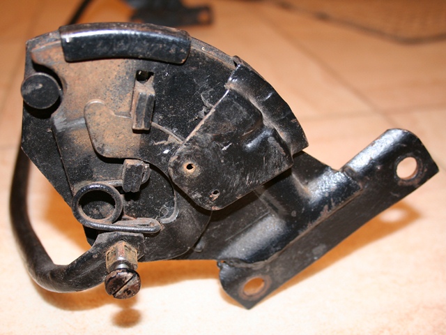
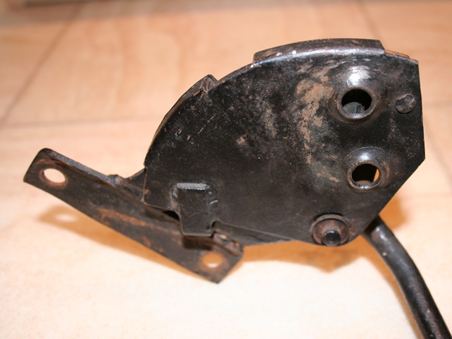
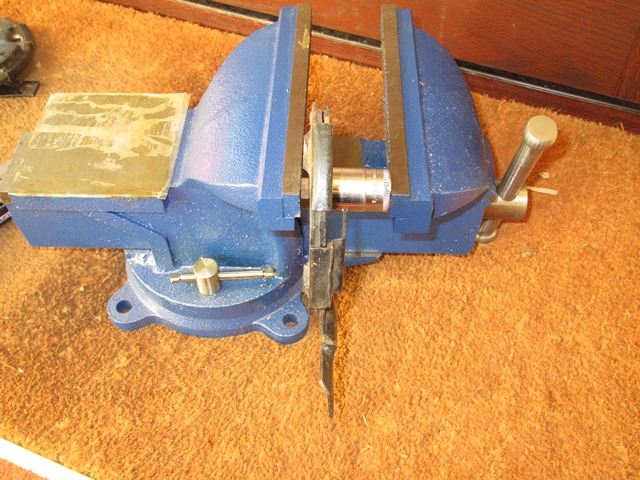
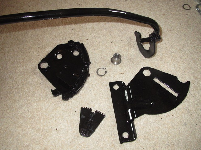
My first attempt was to clamp the hinge unit in a vice, mount the spring pack on the hinge and use pliers to try to open the springs. It was a huge difference between extending a single leaf and the full spring pack! The problem I found was to get sufficient clamping needed to secure the hinge in the vice to withstand the forces needed to open up the springs. Often the hinge would move in the vice in preference to spring opening and, once the paint finish started to show signs of distress, I gave up.

After a few further searches I found an alternative method where the hinge pivot bolt is removed. The spring is mounted to the bracket half of the hinge and the receiving pillar on the hinge arm positioned in the centre of the spring pack. The idea being that the latter could be used to extend the spring pack to a point where the pivot bolt could be replaced. Again all this achieved was to further damage the paint.

Like most problematic issues encountered, I put it off to have a ponder how best to tackle it. Recently someone posted a video on the internet of a rather wacky, counterintuitive way of tackling the problem. I’d not had much joy with the accepted methods so I thought I’d give it a whirl. Nothing ventured, nothing gained.

The hinge was securely screwed to an old 4×2 wooden frame I’d lying around as I still haven’t got round to mounting my vice on a workbench. Essentially the building of the spring pack, covered previously, has simply arranged the leaves in order on the mounting bolt so the spring pack can be fitted onto the hinge bracket.

Inserting the bolt was very fiddly

The individual leaves are then pulled out from the spring pack with pliers, working out from the inner most leaf. The leaf being pulled clear pivots on the mounting bolt and is then extended and placed over the receiving pillar. The process is then repeated for the remaining leaves.

The securing nut on the spring pack bolt only needs to be put on a couple of turns to allow the leaves to pivot. Pulling out the individual leaves with pliers was quite difficult but obviously gets sequentially easier.

I had to use a screw driver to lift each spring to be able to get some strong pliers sufficiently on to the leaf to pull it out. Once a leaf has been partially pulled out, it was occasionally necessary to tease it out further using a screwdriver. The leaf can then be extended using some thick protective gloves and pliers.

1st leaf on! Next leaf pulled out Extending the leaf

I would thoroughly recommend this approach over trying to extend the full 5 leaf spring pack.

 Posted by at 7:03 pm
Feb 142013
 

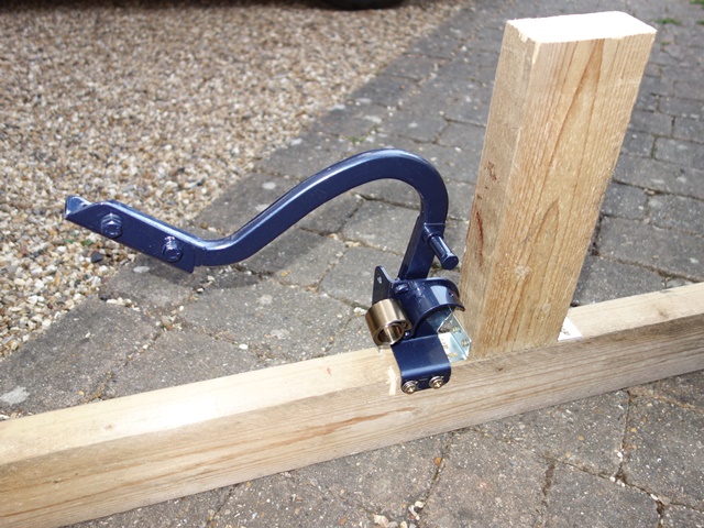
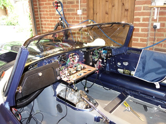
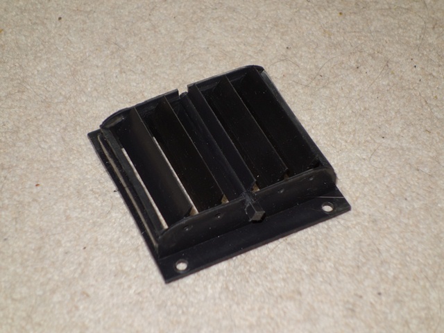
The dash heater controls operate plastic vent outlets on the underside of the dash, one in each footwell. When the vent is open, the air follows the passage of least resistance into the footwells. By closing the vent, this path is blocked and therefore the air is forced to exit via the dashtop windscreen vents.

The vents themselves consist of five interconnected vanes with the central vane connected to the dash control. Operating the dash heater control rotates the central vane, and with it the other vanes, between the fully open and fully closed positions.

Somehow the central vane of one of the vents has either been misplaced or lost during the constant sifting through the boxes of parts. Unfortunately the vents seem to be unique to the Series 2 and, as far as I’m aware, are not available any more.

After fruitless searches of the parts boxes and keeping an eye out at Stoneleigh spares day, I had to bite the bullet and start researching if and how I could fabricate a new vane. The problem is that without the central vane the vent is useless.

I think most plastic parts are generally injection moulded which isn’t really a DIY option. However there are some very low viscosity polyurethanes available that are suitable for moulding which may produce a good replacement. At least having two vents meant I still had a central vane to make a mould from!

A order was placed with MB Fibreglass Supplies who were very helpful in explaining the moulding process and several days later some RTV Silicone Mould Making Rubber (Polycraft GP-3481), Fast Cast Polyurethane Liquid Plastic Casting Resin (Polycraft FC-6720) and black polyurethane pigment arrived. Some white modelling clay (water clay) was also required, which can be obtained from most craft suppliers.

The first step was to produce a two piece silicone mould of the vane. Four ‘L’ shaped pieces of plywood were fabricated with a depth of around 3″ to make a mould housing. Using ‘L’ shaped pieces has several benefits; they can easily be moved relative to each other to obtain the desired mould footprint, clamping together is straightforward and they can easily be removed at the end without damaging the mould.

The mould housing is then half filled with the modelling clay and clay rubbed along the each of the corner joints to seal them. An off-cut of wood and some coach bolts was used as a mini tamping device. The vane was then pressed into the clay until the long lengths of the vane were flush with the clay (ie half above and half below the clay). Finally a number of indentations were made in the clay which will act as key for both sides of the mould.

It was now time to make the first half of the mould with the two-part silicone system, mixed by weight – 10 parts rubber to 1 part catalyst, ably assisted (hindered) by my two nieces who were on mixing and pouring duties. Being a red colour, it was easy to see when the catalyst had been fully mixed into the white rubber part. The mixture was then slowly poured into the mould housing, covering the clay and vane. The technique is to pour slowly and in the same place so that the silicone pushes out the air as it flows over the part being moulded.

The Room Temperature Vulcanizing (RTV) silicone normally cures in around 4 hours although I left it overnight as a precaution as it still felt tacky after 4 hours, probably due to the cold weather. The mould housing can then be turned over so the clay can be removed, to reveal the first half of the silicone mould with the clay indentations now appearing as small peaks.

Traces of residual clay were removed by wiping with a damped cloth to prepare for the making of the second half of the mould. Once dry, the first half of the mould was lightly brushed with Vaseline, diluted in white spirit.

This should act as a releasing agent stopping the second half of the mould sticking to the first. Some more two-part silicone was then poured into the mould housing as before and again left overnight to cure. Now for the moment of truth …. will two halves separate?

They actually separated very easily and the original vane came out without damaging the mould. The quality looked very good although the proof will only come once the new vane had been cast. The final preparation of the mould was to cut a conical channel for pouring in the polyurethane casting resin and an air vent to help prevent trapped air bubbles in the cast.

The polyurethane resin used was a two part product which naturally cures to an ivory white colour so a small amount of black pigment is required to get the desired finish. The mixture ratio by weight of resin part A, part B and pigment was 10:10:1 so the main difficulty was weighing the three parts accurately as the part only weighs 4 grams.

The resin cures in approximately 60 minutes so it wasn’t long before the first cast was ready. The initial impression was very good – even the original casting marks were faithfully reproduced. However the part was far too flexible so the nieces rudely declared it a ‘FAIL’.


MB Fibreglass Supplies were again helpful and thought the cure process had probably been compromised, most likely caused by having insufficient temperature in the component liquids when they were mixed.

A second casting was made after first heating the liquids on a radiator. This produced a much stiffer vane which seemed to stiffen even further once it had been removed from the mould and left on the radiator overnight. I now had two operational heater vents!!

Dec 282012
 

The seats had been a nightmare to remove from the car as the securing bolts were rusted solid and it was virtually impossible to get any penetrating oil into the threads due to the hardura trim beneath the seat. It also became clear that there was a fair amount of movement between the seat bases and the seat backs which would need to be invesitgated and addressed.

The seats in the S2 had the benefit over the earlier cars of being able to recline. The seat base and the seat back are joined by reclining mechanisms at each side, which are operated via a chromed lever. In normal use the seat back is locked in position by the engagement of toothed components within the mechanism.

The operation of the lever disengages the teeth, therefore allowing the seat back to move relative to the seat base. A connecting bar runs behind the seat so that the reclining mechanism is activated on both sides simultaniously and return springs ensure that the mechanisms return to the locked state when the lever is released.

The reclining mechanism showing the connecting bar which operates a toothed locking mechanism and also one of the return springs

The reclining mechanisms are attached to the seat backs by two countersunk screws at each side

Pressing out the connecting bar guides

There were two causes for the excessive movement. The first was as a result of stretching in some of the countersunk holes, for connecting the mechanism to the seat back. The second was due to the loosening of the pivot joint between the two halves of the mechanism.

The pivot joint consists of a round metal cylinder which is lipped at one end. This passes through the outer half of the mechanism until the lip is flush and then through the inner half of the mechanism. It is then MIG welded to the inner half. The pivot joint is cylindrical as it also acts as the pivot for the connecting bar, which has protrusions at each end which pass through the pivot centres.

The pivot joint was very loose on two of the mechanisms and had obviously been meddled with by a previous owner, probably trying to address the excesive play. So I thought it would be a good idea to dismantle them so that they could be repaired and painted.

With hindsight I don’t think they are designed to be dismantled as, to do so, requires the welded pivot joint to be pressed out to provide enough movement to disengage the various parts. I think this must have been what the previous owner had tried before giving up. However I’d reached the point of no return!

Dismantled at last Damage bolt hole In need of repair

The dismantled reclining mechanism. The reclining connecting bar interlocks with the toothed wedge piece to lock and release the seat back

The two parts show where the attachment hole has been stretched, causing excessive movement in the seat backs

The parts were shot blasted and the damaged ones repaired by adding new metal and then grinding back to the correct profile

The welds securing the pivot joints were ground down so that only a small amount of weld remained. They could then be pressed out using a vice. This provided sufficient movement of the connecting bar to disengage it from the interlocked toothed, wedge shaped piece (above left) while withdrawing it from the mechanism. In doing so the two halves of the mechanism then fell apart.

The individual parts were then shot blasted before new metal was added to the parts requiring repair to the stretched bolt holes. They were then ground back to the correct profile. All the parts were then painted in POR15 in preference to powder coating as I felt POR15 would give a much tougher finish.

Painting with POR15 New spray booth! Ready for rebuild

The parts were then painted with POR15 to give a tough coating which should be better at withstanding the abrasion

Hanging the parts to dry

The parts ready for the rebuild, which I wasn't looking forward to! Note: new machined joints and circlip to replace the need for welding

I wanted to avoid the need to weld the pivot joints to the mechanism. Fortunately a local from the pub runs a machine shop and offered to make up some new joints in stainless steel. Rather then being welded, the joints were machined with a groove so that they could be secured with a circlip. If they need to be dismantled in future it won’t be such a difficult task next time around. A week later four shiny new joints were delivered all for the cost of a pint!

At the same time as sorting the reclining mechanisms, the seats were stripped back to the frames as these were going to be sent away to be professionally re-trimmed. It’s possible to purchase re-trim kits which include new leather seat covers but most on the E-type Forum who had rebuild their cars recommended getting the seats and the central console done professionally and I was happy to take their advice!

Seat cover removed Seat back padding Edges covered in cotton

The seat back cover is secured at the base by stables into a plywood strip

The firmness of the seat back is provided by interconnected elastic rubber rings. The black plastic head rest guide had been snapped off.

A fibrous material provides the padding for the seat back

The removal of seat back cover was simply a matter of removing the securing staples around its base. The seat cover can then be slid off to reveal the metal frame and internal padding, covered in a plastic protective covering. The spring in the seat back is provided by a series of interconnecting rubber rings connected to the metal frame and the seat padding is an odd fibrous material. The edges were also padded out with compacted, loose cotton. All of this would be replaced during the re-trim.

The seat runners were removed from the seat bases but the release arms were scrapping on the underside of the metal frame. I suspect this might be due to incorrect shimming or the arms have been bent. I’ll have to sort this out when they are refitted.

The S2 seat runners differ from earlier cars as they have a connecting wire so the runners are released from both sides

The runner release arm was fouling the seat base. I think this is most likely to be incorrect shimming between the runner and the seat base

The seat base covers are similarly secured by staples into a material strip on the underside of the metal seat base frame. This time the padding is provided by a dense foam moulding and the spring by a rubber diaphragm. Both the rubber and foam had started to perish due to age but again these would be replaced.

The seat diaphragm rubber had started to perish

The seat foam was no longer bonded to the seat base so the seat foam and cover could just be lifted away from the frame

One other problem that wasn’t immediately obvious was that the front mounting points were broken. The mounting points are captive nuts which are welded in place however the metal had fractured almost the entire way round the nut. The seat bases were sent off to be repaired by Hutsons, who were doing the bodyshell work as I didn’t have the necessary metalworking equipment …. or the skills!

The seat frames, centre console and some other interior trim were then sent off to Suffolk & Turley to be re-trimmed. I had always envisaged that the car would be painted in British Racing Green and trimmed in a cream leather.

However a late change in paint colour to Oparlescent Dark Blue meant that I now needed to decide on an alternative interior colour. The colour choices offered by Jaguar for the interior for Oparlescent Dark Blue cars were Black, Light Blue and Red. Although I believe it was possible to specify any interior colour in their range when the cars were ordered.

I didn’t want black as I wanted some contrast to the black of the dash. I wasn’t that keen on the light blue …. probably biased because I’d never liked the original light blue exterior. So red it was! Although Eric Suffolk did try to tempt me with the light blue as he said it was his favourite colour. I must admit that Oparlescent Dark Blue with a red interior was probably the last combination I would ever have gone for so I hope it looks alright at the end. Too late to change my mind – I was committed now!

The rebuilt reclinging mechanism with freshly zinc-nickel plated return springs. Boy were the springs difficult to fit without destroying the new paint!

The completed seat, console and trim kit were picked up from Suffolk & Turley. They'd done a fantasic job - just like new!

The hard work and lengthy repair of the reclining mechanisms were worth it. I'm so pleased with the seats and console and now really eager to fit the interior

There was quite a time gap between sending the seat frames and console off to Suffolk & Turley and my finishing the repair of the reclining mechanisms. Work and other things were taking precedence. However I was now holding things up as the seats were awaiting re-covering and Eric was insistent that he needed the mechanisms to make sure the stitch lines in the seat back and seat base were aligned. So I made a last push to get the mechanisms rebuilt before posting them off to Eric to work his magic.

The reclining mechanism also has larger springs ro return the seat back to the upright position. I still need to source the bakelite knobs for the reclining levers

A good view of the connecting bar between the two sides of the reclining mechanisms

The seat frames were powder coated in the correct grey and new diaphragm and seat foam used in the retrim