
The two tried and tested methods for the engine removal are either lifting it out from above or lowering it onto a trolley and then lifting the body sufficiently until the engine is clear of the sub frames. Although I’ve heard of people, doing full restorations, who have lowered the engine onto a trolley and then removed the surrounding engine sub frames.
The difficulty with the removal from above is that the engine and gearbox come out together as a single unit and this requires it to be tilted at the same time as it is being lifted clear. I didn’t have a controllable method of tilting and wasn’t too keen on having such a weighty item dangling at such a height.
 I was also doubtful that my home-made lifting frame, scaffolding cut to make a cross beam supported by A-frames, could raise the engine/gearbox unit to a sufficient height to clear the sub frames. So my only real option was to drop the engine.
The bottom out approach is documented in the Haynes manual and required the removal of all the engine ancillaries, the exhaust and inlet manifolds, alternator, oil filter etc. Once these had been removed I was then ready to lower the engine. Gulp! So far, so good.
At this point I must have taken leave of my senses when making some key decisions and the removal process descended into more of a farce!
 I had some 1″ square Dexion speedframe lying around which included a set of castor wheels so I set about making a makeshift trolley. I’d lower the engine and gearbox on to the trolley, lift the car and then pull clear.
The first issues were the length of the 3-pronged corner connectors and that a length of 1″ square would be required between the connector and the castors. This resulted in a considerably higher platform that I’d originally envisaged.
The knock on effect was that, not only would I have to raise the front of the car even further, I would have to raise the rear of the car to reduce the body angle when the front was raised. This would allow the engine & gearbox to be dropped without hitting the sub frames. At this stage I should have reconsidered my approach to how I was dropping the engine.
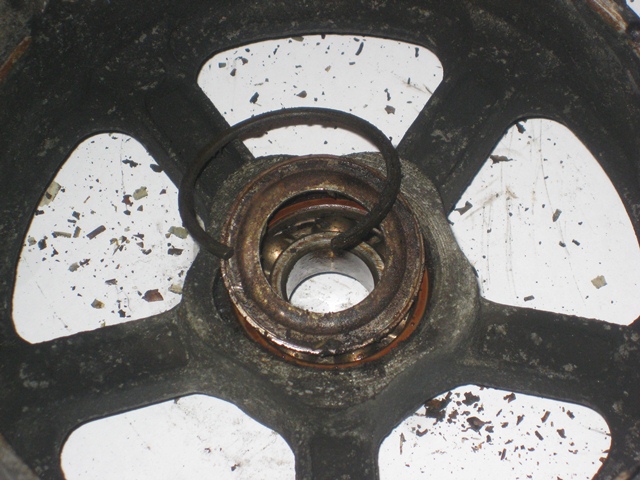
The car was already supported on axle stands so once the ancillaries had been removed, the hoist could be used to lower the engine onto the waiting trolley. The castors were already showing signs of giving way, as can be seen in the photo above! I really should have reconsidered whether it was wise to continue. However, again, I ploughed on. Dooh!
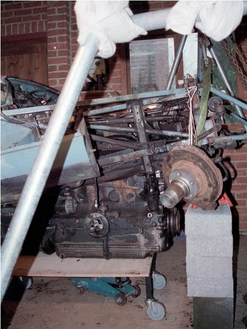 The front and rear were then raised alternately, supported by axle stands on building blocks. The rear was just about within the range of my trolley jacks but the front needed to be lifted via the lifting frame.
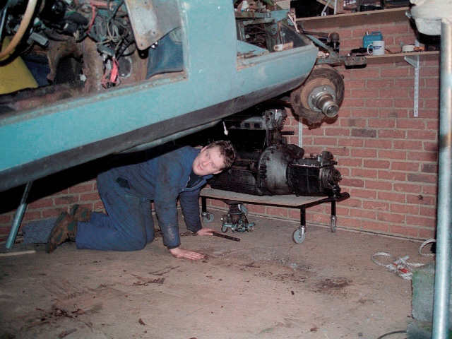
Once the front sub-frame was clear of the engine, the lifting frame was used to take the full weight of the front of the bodyshell. The supporting blocks were then removed to provide an exit route for my wobbly trolley. The trolley castors didn’t approve of being moved and their jaunty angle worsened severely as the trolley was delicately pulled clear!
At this stage I would have been in all sorts of problems had the trolley collapsed “mid-extraction” as the only lifting gear I had was in used supporting the bodyshell!
|
|
|


I did have to realign the trolley legs several times, taking the weight by an extended crowbar. It was very close but fortunately the trolley lasted just long enough to pull the engine clear. It was then mounted on a proper engine stand.
|
|
|

On a positive note, the lesson learnt for the rebuild is to use a more substantial trolley which is as low to the ground as possible and to have a backout plan in case something does go wrong. Even with the self-induced problems, I still think dropping the engine is the way to go!
 The alloy end plates were sent off to be ultrasonically cleaned while I renovated the motor body and internals. The renovation of the motor bodies ended up being a bit of a palaver and took several goes before I was happy with the end result. They were quite heavily rusted and after shot-blasting revealed quite heavy pitting. Rather optimistically, I thought this would be hidden when they were painted with silver Hammerite. What I soon learnt was that paint is not a good filler as the pitting was still clearly visible through the paint. Also I wasn’t happy with the colour of the silver Hammerite compared with the original finish which was a dark silver grey.
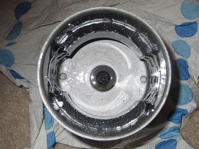
 I finally managed to get a reasonable result by heating the spray can in hot water and the motor body in a low oven. This reduced the viscosity of the paint sufficiently to allow the bubbles to burst and then the paint to level sufficiently before it started to ‘skin’.


 The stator and the various bolts, washers and screws where then zinc-nickel plated using a kit purchased from


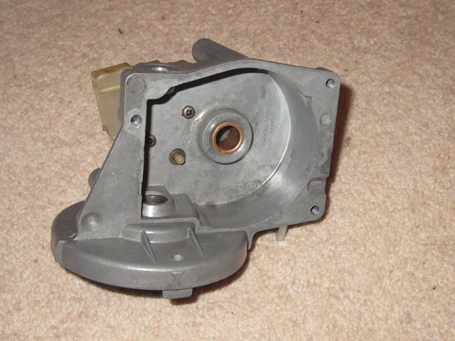
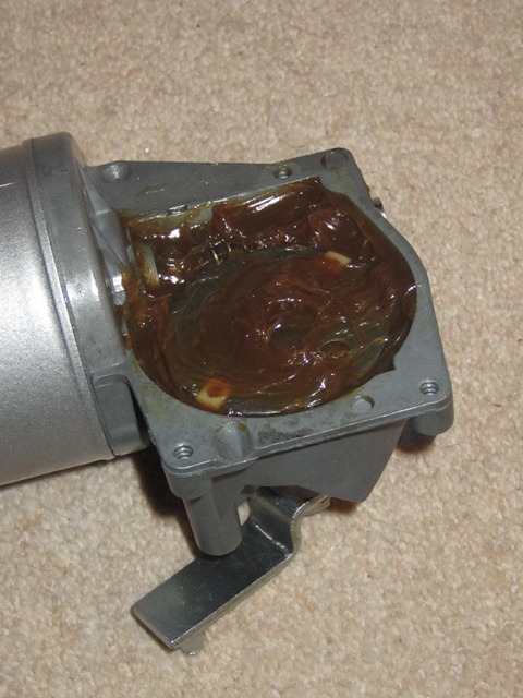
 The centre area of the gearbox lid has been stretched at some point. Therefore its outer perimeter no longer made a continuous seal and so would allow water into the gearbox housing.
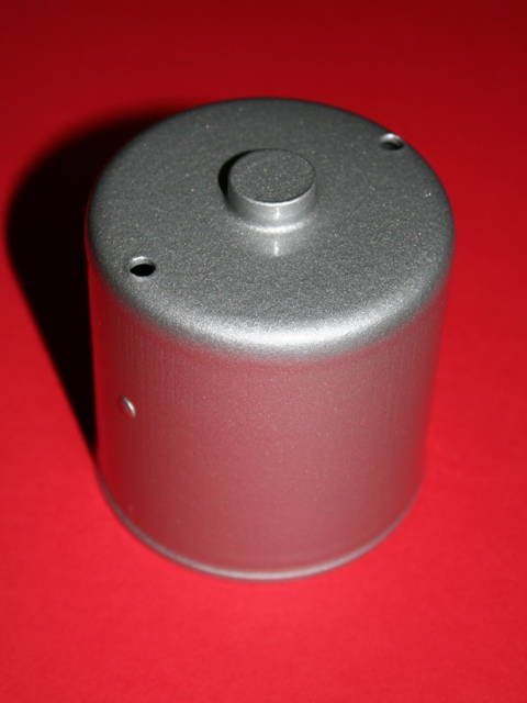 Next up was the yoke which contains the two permanent magnets. The magnets can be removed by lifting the retaining clips so the yoke could then be shot blasted before being painted in silver hammerite. I was quite pleased with the finished article even though the silver hammerite was not quite the correct colour.


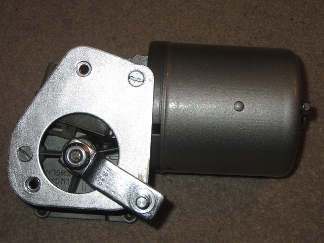


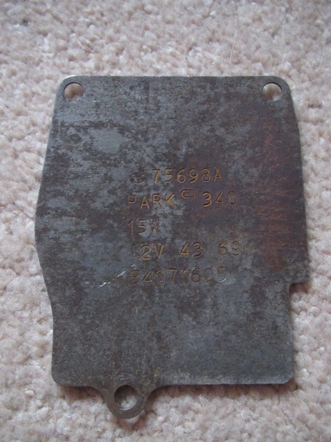
 The wiper motor in the S2 is a Lucas Type 15W motor, the output of which drives a connecting rod to the triple wiper rack. From what I can tell the 15W motor essentially works in the same manner as the DL3 wiper motors used in the earlier cars, except that the parking switch is now internal within the 15W.
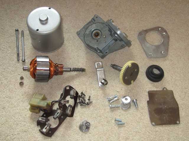
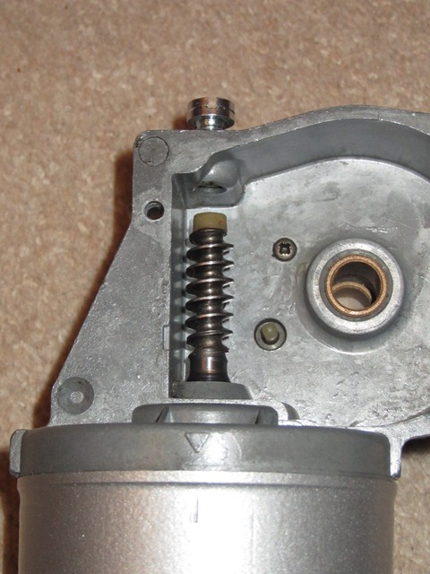
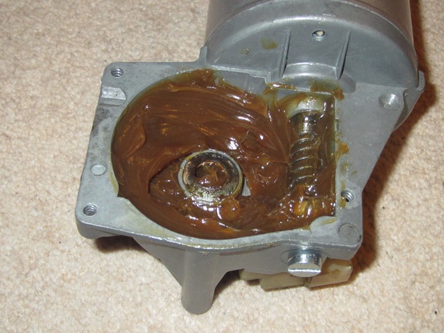
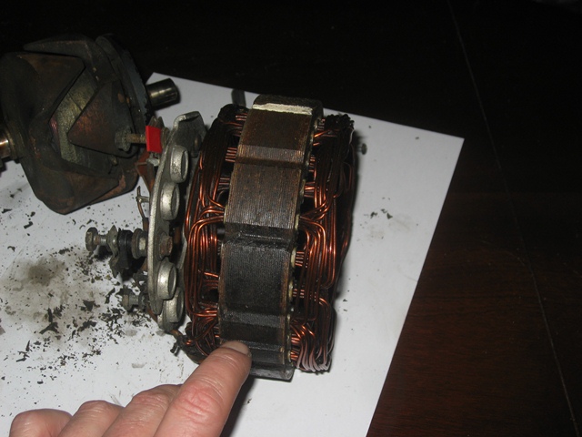
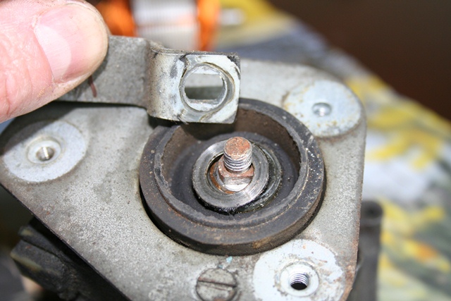
 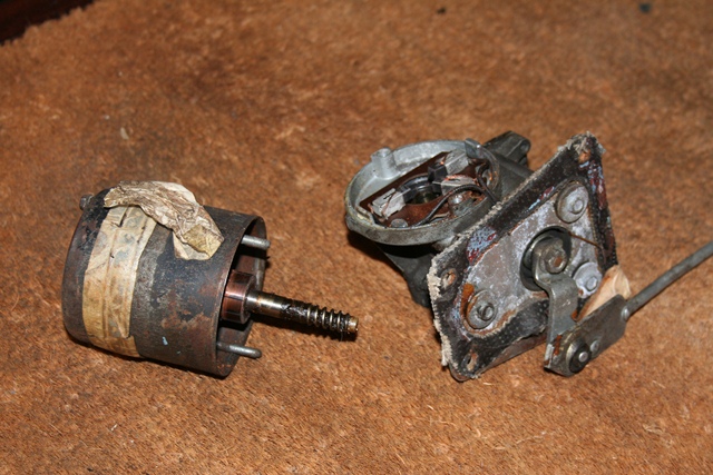 The two long yoke retaining bolts were removed which enabled the round bodied section and armature to be carefully withdrawn until the worm drive is free. Unchecked, the action of the worm drive would pull the armature shaft further into the motor gearbox. A threaded stop screw limits the permitted travel of the armature shaft and there’s also flat thrust washer between the armature and motor gearbox.
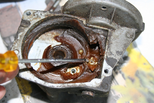
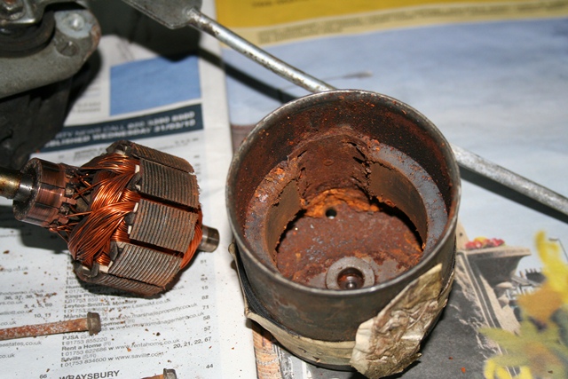 The armature can then be withdrawn from the yoke. Although a reasonable amount of force is required to overcome the magnetic attraction between the permanent magnets and the armature.
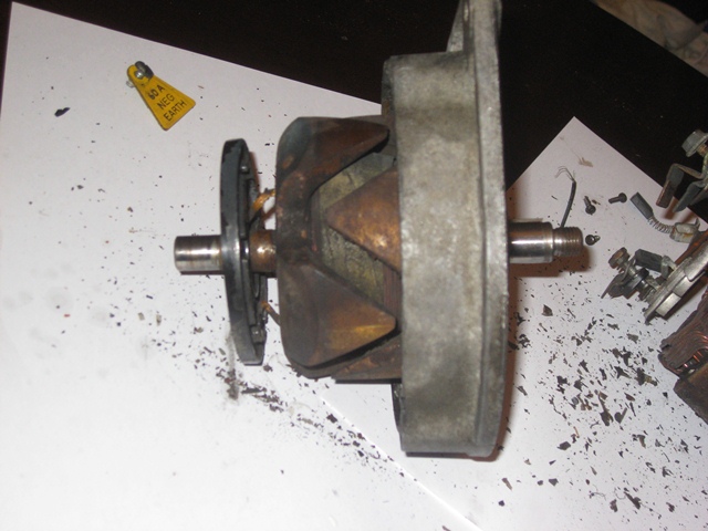
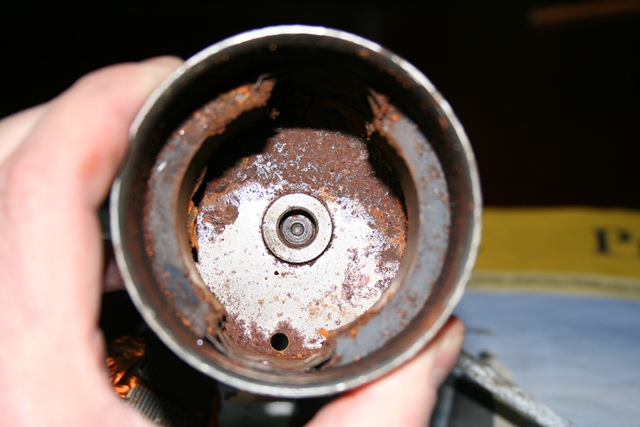 The end of the armature rotates in, what the manual describes as, a bearing housing in the cap of the yoke. However there isn’t a bearing as such. Only a small thrust plate and fibrous washer. I didn’t realise they were there at the time of dismantling so I was lucky not to lose them.
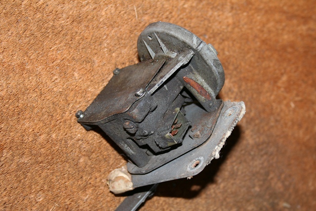 The cover can be pressed back into shape but it immediately pops back, in a similar manner to the lid of an opened jar. I think it’s referred as oil canning and is a result of the centre area of the lid having been stretched.


 It’s a well-known phenomenon that as soon as the dreaded ‘E’ word is mentioned the cost of parts rocket skyward, to whatever the vendor and, being of a cynical nature, the vendor community think they can get away with. The fans being a case in point. At the time, an XJS fan cost £15 while the E-Type fan cost over £30 – an eye-watering mark up! So it’s worth finding out if a part was common to other models/marques.
 As luck would have it, the base of a garden birdfeeder had exactly the same diameter as the original fan. So this was used to cut out the templates, using the same method above.
 The fan could then be rotated until the next blade was under the same section and process repeated until all the blades had been cut to the correct length and profile. The blade ends were then lightly sanded to remove any remaining swarf and were then ready for fitting.
 One of the great things I’ve found about the restoration of the various electrical components is that they were designed in an era before our ‘throw away’ society. Therefore overhauling the units is well within the capability of most enthusiasts. As with the fuel pump, the stripping down of the fan motors was very simple.


 It became apparent that one of the common problems with this SU pump was the tendency for the points to stick, especially on cars stored over winter. After hearing stories of drivers having to use a hammer to whack the pump back into life, I decided it was probably a good idea to upgrade from points to electronic actuation with a kit supplied by
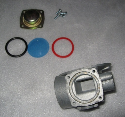


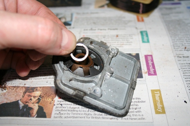
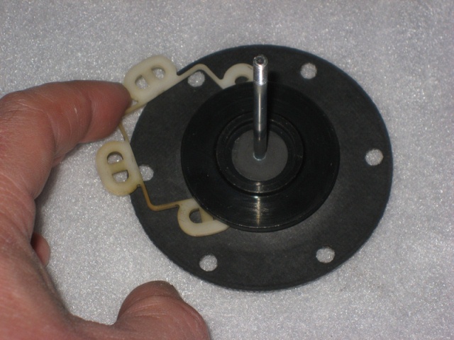 The new armature guides supplied in the repair kit were 5 plastic figures of 8, as shown in the first photo above. The original guide was a single piece and the new guides seemed to be a backwards step rather than an improvement. So the original part was refitted and avoided having to hold five guides in place when refitting the armature/diaphragm into the coil housing.
 Converting the pump to electronic actuation requires a magnet carrier to be attached to the upper end of the armature spindle. First a plastic guide tube is pushed over the spindle down into the coil housing. This centralises the spindle movement within the coil housing. The magnet carrier is fully screwed onto the spindle before being backed off until it is aligned to be perpendicular to the line passing through the pedestal mounting holes. It is then secured in this position on the spindle by tightening an allen screw.
 The bakelite pedestal is replace by a PCB which is mounted on spacers to raise it away from the coil housing. On one of the spacer mountings contains a ‘Hall Effect’ fork. The fork enables the electronic circuit to detect the travel of the magnet carrier and thereby control the energising of the coil.
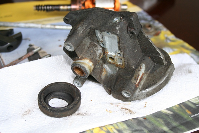
 At some stage one of the cooling fan motors had been replaced with a round-bodied motor which I think must be from a Series 3, shown on the right. So the first task was to acquire a second motor which is correct for the Series 2. One of the vendors at the Jaguar International Spares day suggested that these occasionally came up on the eBay website.
 Oddly, at the end of their advert, they mentioned they were looking to get hold of a boot lid. At some point my car had had a slight shunt at the rear which had twisted the frame under the boot lid’s skin, which is just about visible in the photo. The bodyshop suggested that, although it could be repaired, it would probably cost as much as a new one as the skin would have to be removed to repair the frame.
 The motors were indeed in need of a complete overhaul and for some reason had the white fans mounted back to front. I’m sure this wouldn’t have helped in the efficiency of the cooling and it certainly didn’t help when I came to remove them! Funnily enough, a few days later, an advert appeared on eBay for a basket case restoration of a red roadster, with my blue boot lid! As I said – buyer beware.
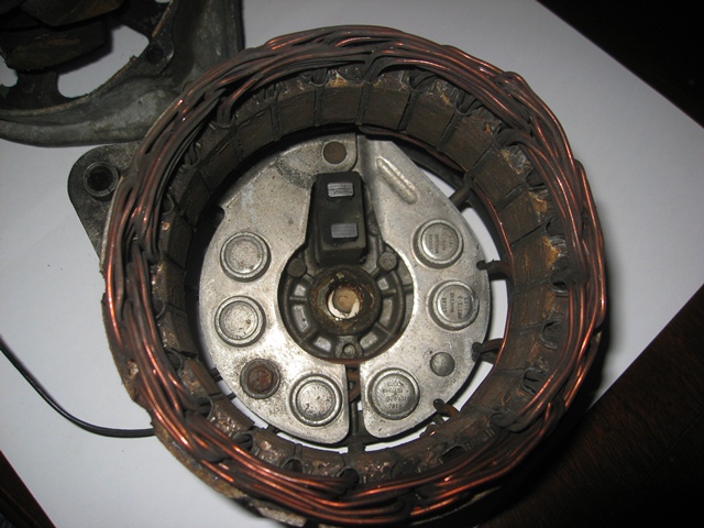
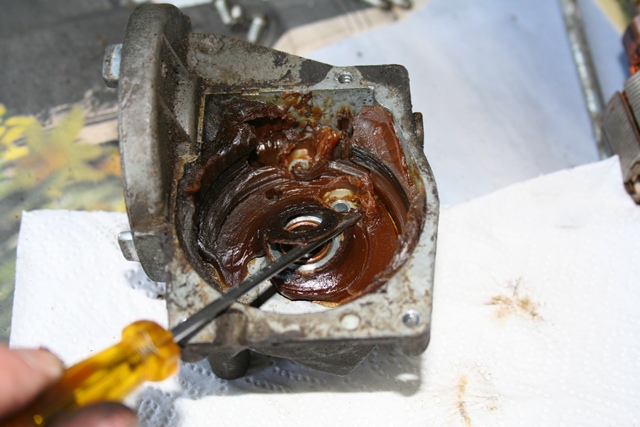
 Once removed from the car, the dismantling of the pump is a fairly straight forward process. I started by removing the six screws around the base of the coil housing which allowed the pump body and coil housing to be separated, revealing the diaphragm and pumping chamber.
 The dismantling of the pump body section was completed by removing the inlet and delivery chamber covers. The inlet cover is simply a cork gasket and cover retained by a central bolt and washer. As far as I can tell the inlet chamber smooths the flow of fuel by having an air pocket which can expand or contract according to the pressure in the chamber. Four screws retain the delivery chamber cover under which is an ‘O’ ring, diaphragm and plastic gasket, see photo. Again the chamber provides smoothing of the flow of fuel due to the flexing of the diaphragm.
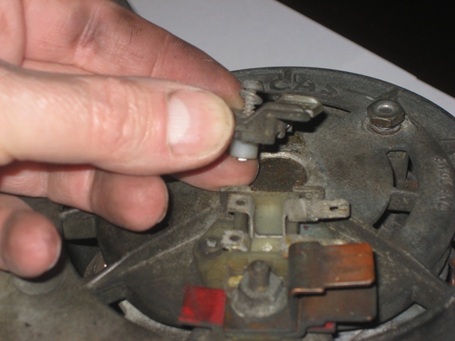
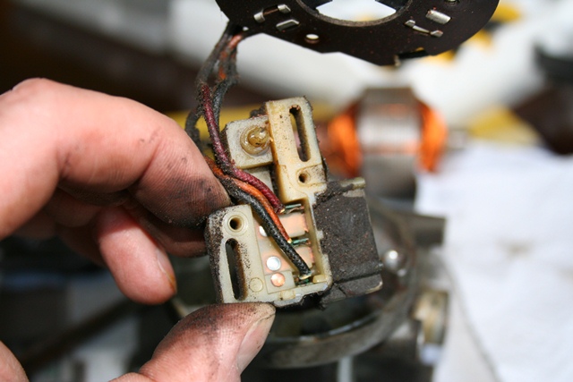
 The disassembly of the coil housing section was also a simple process. The black plastic end cover was withdrawn once the terminal nut had been undone and the tape sealing the end cover/coil housing join removed. Underneath the cover is the contact point assembly, which consists of a Bakelite pedestal holding the sprung upper contact points and a rocker mechanism holding the lower contact points. A small capacitor is connected between the upper and lower contacts to suppress arching across the points gap as arching causes premature deterioration of the contact points.
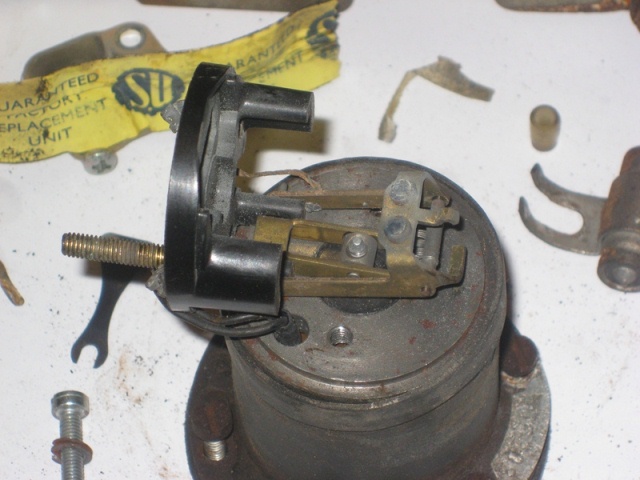 After the two screws had been removed the pedestal could be rotated away from the rocker mechanism. Both the upper and lower contact points were badly corroded. Finally the rocker mechanism and armature & spindle were removed. This can be achieved by disconnecting the leads to the rocker mechanism and then rotating it until free from the spindle. Alternatively the armature/diaphragm can be rotated anticlockwise until the spindle is free of the rocker mechanism.
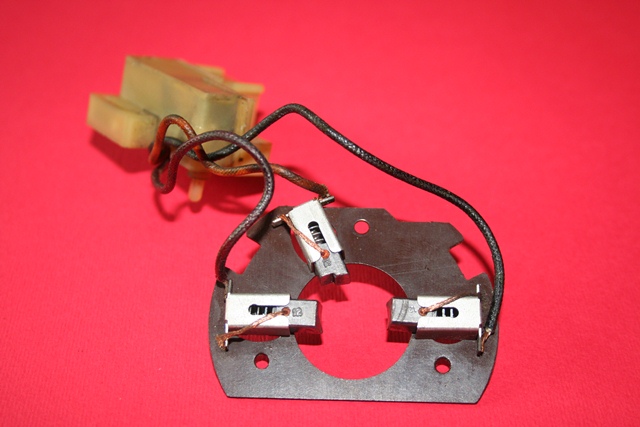
 When the pump was first removed what appears to be a capacitor (see the photo on the left) was connected across the positive terminal and earth. This part doesn’t appear on the Jaguar parts list so I assume this must have been added at a later stage. As previously mentioned capacitors were used to suppress electrical arching but I’m not sure whether this capacitor was added for this reason or possibly to suppress electrical interference produced when the pump is in operation.