My list of tasks to finish off the interior trim has been getting shorter and shorter, without even lifting a finger …. meanwhile Suffolk & Turley’s list has been getting longer and longer! The two vinyl-covered panels for each B-post were offered up and it appears that some metal might need to be removed from the panels. So I thought it best to consult them before getting the grinder out!
The first panel is attached to the face of the B-post and creates a ‘closing’ flange against the door card. It needs to be positioned to:
- allow for the thickness of the door card
- finish level with the top of the B-post
- allow the doors to close beyond their natural closed position in order to latch
Ensuring there is sufficient room to latch means there will always be a slight, ideally parallel, gap between the panel and the door card.
| Uneven gap between panel & door card | The panel also protruded into the cabin | Outer panel was missing mounting holes |
|---|---|---|
 |
 |
 |
However the panel’s inside edge protruded beyond the face of the B-post. This in turn pushed the second outer panel, which wraps around the face of the B-post and into the cabin, away from the body. It became a trade off between achieving a parallel gap and how much it protruded.
Making sure the top of the panel was flush with the top of the B-post determined the size of the gap at the top, between the panel and door card. Closing this gap would require the panel to be raised slightly and metal removed from the top of the panel to return it to being flush.
Alternatively, sticking to this gap down the full length of the B-post would require the panel to be rotated, moving the bottom of the panel inboard. This could only be achieved by taking metal off the lower edge as it is already hard against the sill. It would also cause it to protrude further into the cabin and so need the inner edge to be cut back as well.

Trim panel was welded!
Also I was expecting the larger wrap-around panels to have two holes in the metal for clips to secure them to the B-post. Another difference was the replacement trim panels were much wider at the base.
The open day at SNG Barratt was an excellent opportunity to look over a number of different cars to see how these panels should be fixed.
On a couple cars, notably a lovely OSB S2 OTS, both panels were fixed with chrome screws with cups. Although my original panels didn’t have any screw holes. One thing is for sure … I definitely won’t be attaching it as I had found it …. welded!!
Also I can’t for the life of me work out how the outer sun-visor brackets fit with the A-post finishers. I had assumed it should be fitted behind the finisher but it would then be impossible to fit the nut on the visor attachment.
| Door card clips also used to fix A-post finishers | Although stumped how the visor bracket fits! |
|---|---|
 |
 |
For now I’m leaving the sun visors off and will ask Suffolk & Turley about it when it’s up having the hood trimmed.
Boot Space

Dynaliner used in place of jute
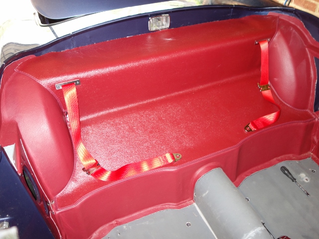
Originally the bulkhead in the boot space was covered in jute which was then overlaid with Hardura. The trim kit didn’t include this piece of jute so some 1/4″ Dynaliner was fitted in its place.
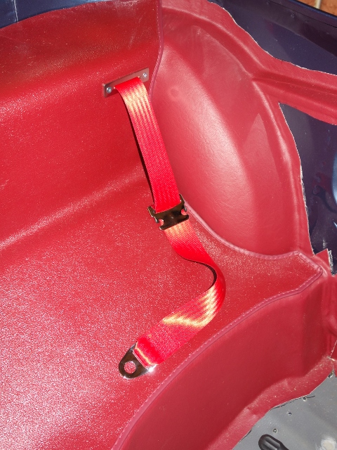
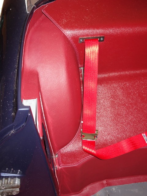
Fitting the inertia reel in the boot caused far more trimming issues than I’d expected, taking two attempts at the Hardura until it was acceptable. The reels are located as far outboard as possible which required the side cards to be fitted before the reels.
The downside of this and the desire to make the installation as neat as possible (hiding the bolts securing the reels under the rear bulkhead Hardura), means that if access is needed to either the fuel filler area or fuel pump in future, the side cards may have to be sacrificed. Also the new cards would probably need to be modified with cut-outs for the reels in order to re-fit them.
| Boot bulkhead and side cards | Side cards secured by #4 screws & cups |
|---|---|
 |
 |
The side cards were simply held in place along the upper trailing edge by three #4 self-tapping chrome screws & cups.
The boot boards weren’t original and needed replacing anyway but were useful in providing templates for the replacements in marine grade plywood. I believe the originals were also painted black but it seemed daft to go to extra expense and lose the wood finish. So they were treated with finishing oil to keep out moisture.
The left hand board is permanently secured by three #10 self-tapping screws – for some reason the front two are slotted countersunk screws & cups and the rear one with a hex head & washer! A metal bracket is also attached to the underside of the board to support the RH board.
| Boot cable passes through oval hole | Front attachment of LH boot board |
|---|---|
 |
 |
A number of rubber pads are inserted into the bracket to stop the RH removable board from rattling. However the repro pads were quite tall so the only way I could get the two boards to lay flat was to fit a strip of wood under the bracket.
| Additional strip of wood under bracket | Strip matches height of rubber pad |
|---|---|
 |
 |
As the RH board needs to removable, the rear is held against the boot board flange by a clamping bracket, which is riveted in place. Its shape acts as a spring pressing the board against the flange but allows it to be withdrawn by pulling it forward.
The front of the board is held down by a stud that presses into a retaining clip, riveted to the flange. The stud was attached to the board using a Tee nut insert. Originally the board just had a finger hole cut into the board to lift it, although I decided to fit a brass ring pull instead.
| Rear clamping bracket | Front stud and clip |
|---|---|
 |
 |
The only way I could get the petrol tank to fit was to remove the stud clip. So it had to be riveted back in place. Although I’m not convinced this should have been the case to remove the tank!
| Measure twice, cut once – locating stud position | The stud clip riveted back in place |
|---|---|
 |
 |
The final task was to fit the four pop-fasteners to hold down the Hardura covering the floor of the boot. I used some blu-tack spread onto the boot floor/boards to locate the required positions of the male connectors. Pressing down on the Hardura stud left a suitable imprint.
| Boards in-situ | Marking pop-fastener positsons |
|---|---|
 |
 |
The wires hanging down on the left hand side are for an LED boot light that will be operated by the boot hinge making contact with a mirco switch.
Radio console and central console

Angling the centre consule
under the radio console
I was expecting trouble fitting the radio and centre consoles …. and I was not disappointed! The radio console with all the stereo wiring was relatively easy to put in place, although not secured at this stage.
The centre console needs to be slotted under the radio console and then lowered at the rear, while feeding both the handbrake lever though its slot and the gear stick into its gaiter. Easier said that done!!
No matter how I positioned the handbrake and gear lever, I just couldn’t get the console over them both at the same time. Some advice posted on the forum for troublesome consoles was to disconnect the handbrake cable to provide a greater range of movement.
Still no joy! Success was finally achieved by detaching the whole handbrake from its mountings. Although it was short lived. The whole console then couldn’t be pushed forward to enable the rear to be lowered to the floor.
It needed quite a bit of Dynaliner underlay to be removed from underneath the radio console and easing the sides of the console apart before it fell into place. It was so tight I was questioning the wisdom of adding the 3mm foam under the lower bulkhead Ambla!
Seats and seat belts
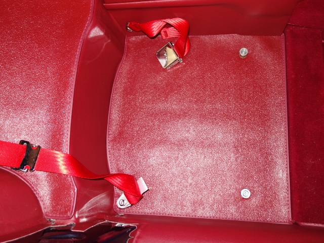
The under-seat Harduras were next. Holes were cut, or more accurately drilled, for the seat bolts and the seat belt anchor bolt. The location of the holes was found by pushing a thick needle up through the bolt holes from beneath the car.
The seat’s front mounting points have a thick spacer to raise the seats so the slider release bar doesn’t foul the carpeted floor strengthener.
| Seat mounts and belts installed | Gratuitous interior shot as it nears completion! |
|---|---|
 |
 |
I wasn’t sure if these spacers should fit above the Hardura or pass through them. In the end, the length of the mounting bolts dictated larger holes were needed so the spacer could pass through to the floorpan.
Spacer sized holes had been cut in the Koolmat when it was fitted, which wasn’t necessary for the rear seat mounts. So two spacers were used – one inserted to fill the hole in the Koolmat and one to raise the seat runners off the Hardra.
| A needle was press through Hardura to locate the mounting holes |
The seats slide onto the front mounts & secured by screws & spacers at rear |
|---|---|
 |
 |
The buckle ends of the seat belts were then mounted to the transmission tunnel through holes in the centre console. At last the seats could be put in to finish off my side of the trimming.
Rear view mirror

Loctite kit worked a treat
I made the mistake of purchasing some double–sided tape from Halfords, sold specifically for the task of attaching rear view mirrors. As with all of their products, it was monumentally useless for the task it was designed. The mirror was found lying in the footwell the morning after it had been fitted. It hadn’t even been subjected to the expected vibrations of normal driving or being adjusted.
The second attempt was made with a Loctite kit and was much more successful. The mirror button is bonded to the windscreen with a strong adhesive, activated by a mesh fabric. The bonding only takes a minute to secure the button and is fully cured in 15 minutes.