
The separate wiring loom for the starter solenoid relay was sent off to Autosparks so they could have a look and use it as a pattern to make up a new loom.
In the meantime, I’d posted my wiring dilemma on the E-Type forum to see if others could shed light on the relay wiring. A fellow S2 owner kindly pointed out that there was a change to this area of the wiring during the S2 production run. As it happens, at exactly the same time my car was passing through the factory. I guess that it hadn’t been reflected in the service manuals because the modification had been made mid-production run.
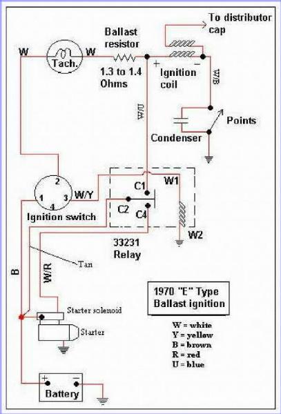 Around the end of ’69, a ballast resistor was introduced into the ignition circuit with the aim of improving cold starting. The original 3 ohm coil was replaced by a ballast resistor and coil wired in series, both being around 1.5 ohms. When the ignition switch is turned to start the engine, the starter relay activates, delivering power to the starter solenoid but also bypassing the ballast resistor.
Therefore when starting, the full 12 volts is applied to the coil. The spark energy is increased over the original setup as the current flowing into the coil is greater due to the lower coil resistance.
Once running, the ballast resistor is introduced back into the circuit. As the coil and ballast resistor have a similar impedance of around 1.5 ohms, the voltage drop across each is roughly the same. Therefore a voltage of 6v is applied to the coil during normal running.
I found the wiring diagram above on one of the American Jaguar sites which shows the wiring connections for ballasted cars. Autosparks also confirmed that they stock this ‘ballast resistor’ loom. Although I think I’ll get the car running before I cut and tape the unused wires in the main loom!
 It was a good opportunity to get Autosparks to make up the additional wiring, using the correct colour coding, that I needed for the few upgrades I’d planned – the mechanical brake light switch to supplement the hydraulic switch and the boot light.
There was also a number of wires that I believe are missing from the sundries wiring pack, such as earthing wires for the rear light clusters and a beefier jumper wire between the two brown fuses. Touch wood, I’ve now got everything to complete the wiring.
Alas, it was again a case of one step forward and two back. Very early on in the work on the bodyshell, the LH outer pedal side panel had been replaced where the main loom comes out behind the voltage regulator bracket. The panel was from one of the main suppliers of panels so I foolishly assumed it would be spot on.
 It was only once I came to fit the voltage regulator bracket that I found out that its mounting holes had been punched in the wrong place. They were about 5-6mm too close to the sill closing panel so that the bracket doesn’t fit. The bracket did change for the S2 cars so it might be that the panel also changed and I was supplied the wrong part.
Either way – not happy! I should have checked it well before it had reached the paint shop. It’s not the end of the world but it will always niggle me as I’ll know it’s not correct on the car. The annoying thing was I’d spent ages sourcing and refurbishing a replacement bracket, as the studs on the original had all sheared trying to remove it.
The first replacement was purchased from SNG but the fitting was incorrect, using bolts rather than attached studs. Some time later, I managed to get a rather tatty one on eBay which was covered in a mixture of black and green paint. It took several applications of Nitromors and wire brushing before it was good enough to be re-plated.
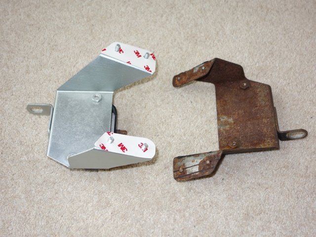 The problem I find with zinc plating is it’s too blingy (although I’m sure the brightness would dull slightly once exposed to the elements). I decided to experiment and sprayed it with a two-pack clear satin lacquer. The results were even better than I had hoped/expected. The satin finish obviously tones down the brightness but it also has a softer, smoother to the touch feel and a more uniform metallic finish.
After all that effort I didn’t really want to start butchering a perfectly good original part to fit. instead I planned to trim the original bracket to fit and then repair the welded studs but SNG Barratt now supply the brackets with the correct studs relatively cheaply. So I’ll adapt one of their repro parts rather than an original part.
I think I’ll also spray most of the plated parts in the engine bay with the clear satin lacquer. Hopefully it will also provide a more durable finish.
Sorry, the comment form is closed at this time.