Chris

Apr 152012
 

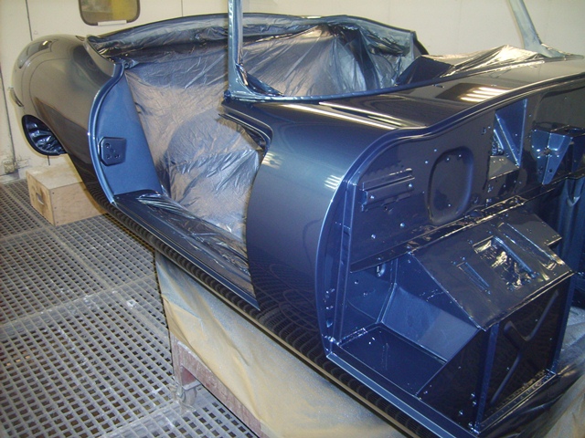
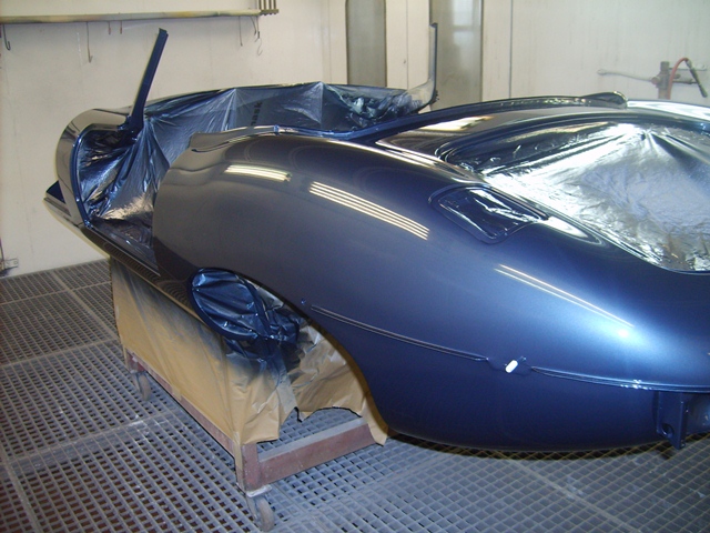
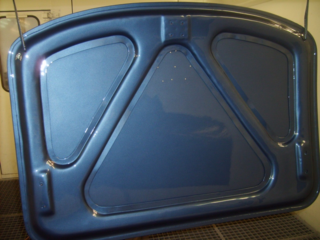
Hutsons have fabricated wheeled trolleys so bodyshells can be easily moved between the body repair, paint preparation and spray booth areas. They’re designed so the shell is at a reasonable height to work on without the need to stoop.

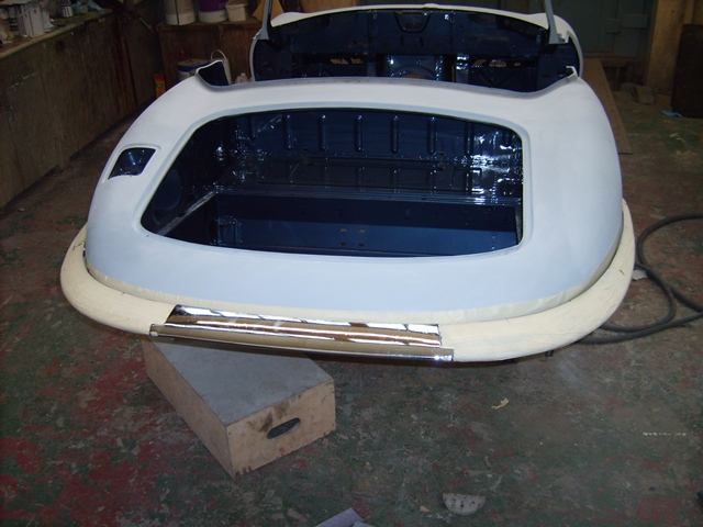
Once completed, the bodyshells are then delivered bolted to the trolley which posed the first problem for the rebuild. How to get the painted shell off the Hutson’s trolley and onto my waiting axle trolleys.

I had initially planned to do the body work myself and had started to make a rotisserie during the dismantling stage. Its base was a rather substantial affair, built out of lengths of 150mm mild steel channel. The car was delivered to Hutsons on the frame, but as I wouldn’t have further use for it, I left it with Hutsons to dispose of or use as they wished.

They’d put it to good use. When the bodyshell was delivered, they had modified their lorry’s tailgate so the long lengths could be bolted on to act as ramps. Their trolley could then be rolled down the ramps in the channels to safely deliver completed shells.

Unfortunately there wasn’t enough manpower around when the car was delivered to lift the bodyshell onto the axle trolleys. It had to remain on the Hutson trolley while I pondered what to do.

Even with the axle trolleys at their full extension, the bodyshell still needed to be lowered by approx. 40cm. None of the local hire shops had anything suitable to raise and support both ends to allow the trolley to be removed and then lower the bodyshell.

I then looked at erecting four columns of building blocks to support timber cross beams. This would also need two other columns to provide a raised base for the trolley jacks. The number of building blocks needed was mounting rapidly, making it a rather expensive solution for a one off job. I was stumped.

The timely delivery of some timber for a workshop provided just enough wood that could be temporarily half-inched to make supporting platforms either side of the car. Also I wasn’t comfortable attempting to lower the bodyshell on my own and drafted in some much needed help.

An initial recce was duly arranged to plan the lowering however it was soon decided to go for it and the oversized Jenga operation began. The bodyshell had to be raised and lowered a number of times – raise, roll the trolley forward until it hit the platform supporting the jack, lower, reposition the jacking platform. Finally the trolley’s exit route was clear and it could be pulled free.

It this point the bodyshell was in its most precarious position, supported only by three jacks. Not good for the nerves!! The final lowering was relatively simple. The front and rear ends were raised and lowered in turn with a layer of timber removed each time.

With the sun low on the horizon, the bodyshell was at last resting on the axle trolleys. Phew!

 Posted by at 10:04 pm
Mar 232012
 

The final stages of preparing the bodyshell for the paintshop and the final painting flew. Andy kindly provided regular emails with photos of the progress and then finally it was all complete and ready for delivery.

I’m really pleased with the final finish – the panel gaps are spot on and the paint finish is excellent. Probably better than how they left the factory. I wouldn’t hesitate to recommend Hutsons. The very long lead time was worth the wait and it’s probably a testimony to their quality of work that Hutsons have a healthy waiting list.

 Posted by at 10:05 pm
Mar 202012
 

My initial plan for the renovation of the alternator was mainly cosmetic but also to check, and replace where necessary, the slip rings and brushes. Slip ring wear can be determined by removing the brush holder and they had definitely seen better days. They were quite heavily grooved so the renovation soon turned into a full rebuild. At this point I started to research the workings of the Lucas 11AC alternator to help understand what I was taking on. I came across the Rootes website which covers an upgrade of the internals to a more modern design.

The upgrade involves adding an additional three rectifying diodes, the output of which will be used to energise the field coil. The main benefits would be that by changing to be self-energising, the rotor winding wouldn’t be susceptible to burn out in the event of the alternator belt failing, there’s no need for the alternator relay or 3AW ignition light relay and it provides a “softer” start, therefore providing better protection for the other electrical components.

Unfortunately I had destroyed the 3AW relay when the car was dismantled – one of its spade connections was more strongly attached to the female connector on the wiring loom than the relay itself and broke free! I’d also read that some viewed the relay as a weak point in the charging system and prone to failure, although modern solid state units are available.

It made sense to make this upgrade while the alternator was dismantled and would avoid needing to source a new 3AW unit. The upgrade didn’t appear to be too complex and hopefully within my DIY skills!

The diagram is for a positive earth alternator but does reflect the interior component for negative earth models

The main components of the Lucas 11AC alternator are; the alloy drive end bracket, the rotor, the stator laminations & windings, the rectifying diode heatsink and the alloy slip-ring end bracket. The diode heatsink is attached to the rear casing via three insulated threaded studs, which act as the electrical terminals. The stator is clamped between the two end brackets with the rotor passing through the middle.

The dismantling of the alternator proved to be much harder than the other electrical components. This was because the design uses a woodruff key which, despite all efforts, was refusing to come out. The woodruff key is a semi-circular disk that is inserted into a slot in the alternator shaft, leaving a protruding tab. This tab mates with key slots in the belt pulley and cooling fan to prevent them from rotating relative to the shaft. The pulley and fan are held in place by a retaining shaft nut and can be withdrawn, once the nut has been removed, to reveal the key.

A slot in the pulley mates with the protruding woodruff key

With the end nut removed, the pulley and fan can be removed

The woodruff key is then revealed - on the left hand sie of the shaft

The difficulty in removing the key was that it did not protrude enough to enable a drift to get onto the end of the key with a sufficient angle away from the shaft. After many frustrating hours getting nowhere, I decided to do some research on the internet in the hope that I would find useful tips on how to remove them. After many frustrating hours surfing the internet and getting nowhere, except for pearls of wisdom as useful as a chocolate teapot (“then remove the key with pliers”), I left it for several days to have a re-think.

In the meantime the rest of the alternator was dismantled by removing the three clamping bolts holding the unit together. This enabled the alternator to be split in half; the front drive end bracket & rotor and the rear slip ring end bracket with the attached rectifying diode heatsink and stator.

Complete unit prior to dismantling

Rear slip-ring end bracket with the rectifying diode heatsink and stator

View of rectifying diode heatsink which houses the six button diodes

As mentioned, the diode heatsink is attached to the rear casing via three threaded terminal posts. Once the external retaining nuts have been removed from the terminals, the stator and diodes heatsink can be withdrawn. The two are connected by the wires for the three stator windings.

Care was taken to note the various insulating washers and fittings on the terminal posts. Both the B+ and AL posts are insulated from the slip ring end bracket while the third terminal post acts as the negative earth connection. The plastic housing holding the sprung slip ring brushes was removed, followed by pressing out the rotor shaft bearing from the rear casing.

Electrical connections at the rear of the alternator

Removing the plastic housing cover reveals the rotor brushes, which can then be withdrawn

Stator and stator winding, with the diode housing attached

I could put it off no longer – the woodruff key had to be removed. The solution that finally worked was very Heath Robinson, essentially using a vice to press the bottom of the key into the shaft. This caused the key to rotate in the slot resulting in pushing the upper part ever so slightly outwards but enough to get a drift onto it. It still required a reasonable amount of force to drift it out but at least I could now continue.

Now the key had been removed the rotor and front casing could be separated. All that remained was to remove a circlip holding in the front rotor bearing so it could be pressed out. The bearing had almost seized solid and couldn’t be rotated by hand so I was glad I had decided to overhaul the whole unit. The two end casings were then sent away for ultrasonic cleaning while parts were sourced for the upgrade/rebuild.

The commutator was showing signs of wear so it was removed. Replacements are still available

Grooves had started to form in the commutator where the brushes make contact

Finally the front rotor bearing was removed

Feb 242012
 

The final task before the colour is put on the outside of shell was the trial fitting of the rear bumpers at Hutsons. Unfortunately all three sections of the original bumper were beyond repair due to a minor rear-end shunt, which had left a neat crease down the middle of the centre section and both out sections being bent out of shape.

Time pressures resulted in new bumpers having to be used, which wasn’t ideal. I’d heard these can be thinner than the originals and the chrome less durable. Only time will tell. Anyway, at least the trials and tribulations of trying to get a complete set of original bumpers was over!

I had planned to refit the LHS section which I thought didn’t look to bad. Therefore I set about obtaining the other two sections as bumpers regularly come up on eBay but it has ended up being an expensive series of disasters! First up was a centre section that the seller insists was posted but it never arrived. The blame placed on the Christmas post. Next, and by far the worse, was purchasing of a ‘complete’ Series 2 rear bumpers from a guy who I believe is a regular on the Jaguar spare parts circuit. The bumpers looked undamaged and all the brackets were correct for the Series 2 …. I was pleased with my purchase.

Only when Hutsons came to trail fit these did it transpire that they were in fact butchered Series 1 bumpers. On the Series 1, the rear lights sit just above the bumpers, which have indentations for the lights. However, with the Series 2, the rear lights moved below the bumper so there were no indentations. For some reason, only known to themselves, someone had cut off the original brackets from a set of S1 bumpers and welded in their place (admittedly very neatly) Series 2 brackets.

The galling thing is that I suspect the seller knew this all along, since he was the owner of half a dozen Jaguars and used to be a main dealer. I will be having words when/if our paths cross!

 Posted by at 9:40 pm
Feb 232012
 

A rather grubby wiper motor
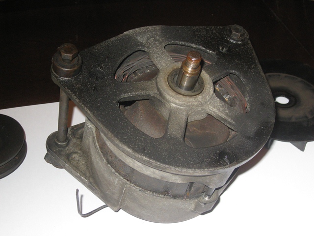
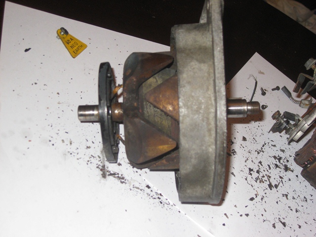
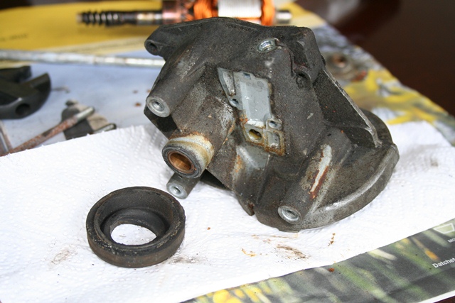
The wiper motor in the S2 is a Lucas Type 15W motor, the output of which drives a connecting rod to the triple wiper rack. From what I can tell the 15W motor essentially works in the same manner as the DL3 wiper motors used in the earlier cars, except that the parking switch is now internal within the 15W.

There are two main sections of the wiper motor; a round bodied section (which acts as the yoke, completing the magnetic circuit) and the motor gearbox. The round bodied section has two permanent field magnets attached to its inner wall and houses the motor’s armature. At the end of the armature shaft is a worm drive that drives the geared output shaft in the motor gearbox.

Worm drive at the end of the armature shaft
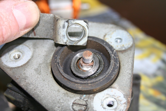
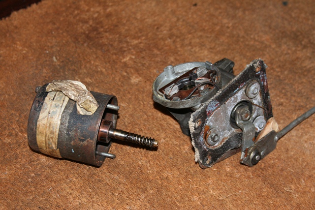
The two long yoke retaining bolts were removed which enabled the round bodied section and armature to be carefully withdrawn until the worm drive is free. Unchecked, the action of the worm drive would pull the armature shaft further into the motor gearbox. A threaded stop screw limits the permitted travel of the armature shaft and there’s also flat thrust washer between the armature and motor gearbox.

The internals were quite badly corroded ... like everything else!
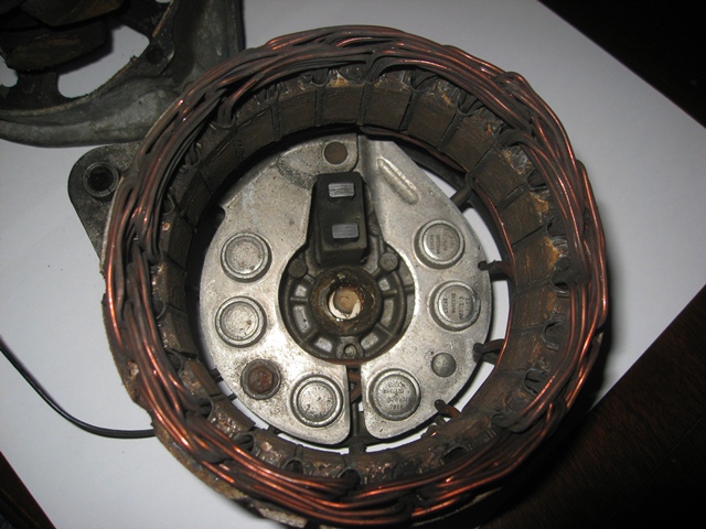
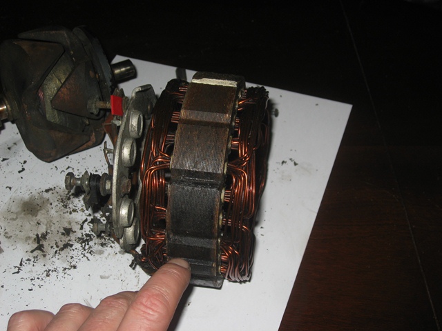
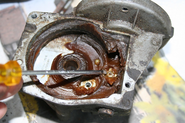
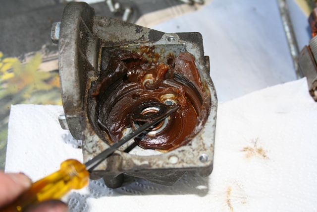
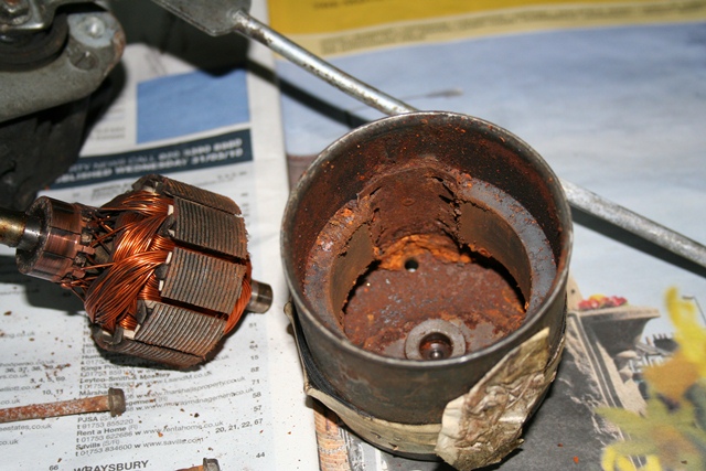
The armature can then be withdrawn from the yoke. Although a reasonable amount of force is required to overcome the magnetic attraction between the permanent magnets and the armature.

The interior of the yoke was fairly heavily rusted and all the tiny, loose rust particles were now annoyingly attached to the permanent magnets.

The thrust plate and fibre washer in the 'bearing housing'
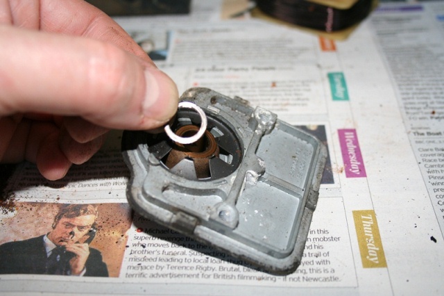
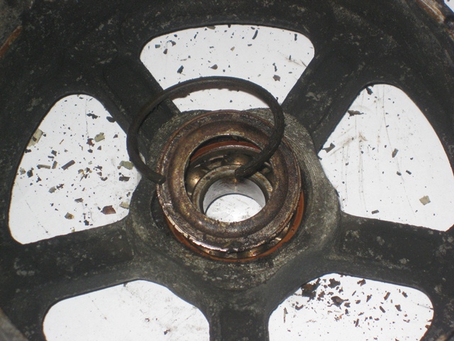
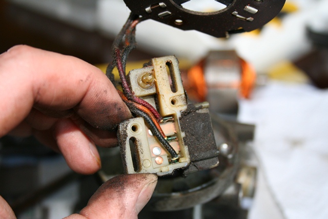
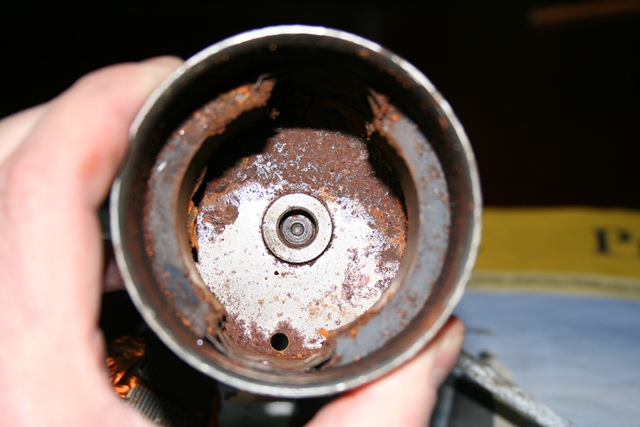
The end of the armature rotates in, what the manual describes as, a bearing housing in the cap of the yoke. However there isn’t a bearing as such. Only a small thrust plate and fibrous washer. I didn’t realise they were there at the time of dismantling so I was lucky not to lose them.

A cover on the main motor housing provides access to the geared output drive. Sometime in the past this cover had become deformed and so it no longer provided a tight seal around its full perimeter (just about visible in the lower photo to the right).

The main housing cover had been deformed creating a gap which would allow water in
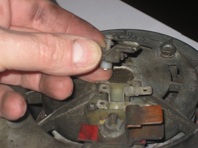
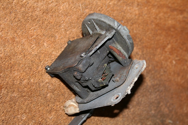
The cover can be pressed back into shape but it immediately pops back, in a similar manner to the lid of an opened jar. I think it’s referred as oil canning and is a result of the centre area of the lid having been stretched.

It should be possible to reverse the stretching by heat shrinking the centre of the plate but that will have to wait until the rebuild.

Removing the cover revealed copious amounts of thick brown grease. I think the grease had dried out long ago and it was surprising the motor was able to turn at all! The rest of the dismantling was very straight forward.

Hardened grease within Worm drive engaged Triple armature brushes

Over time the grease had dried out and hardened. It was surprising the gear could actually turn

Armature worm drive re-engaged for photo. Armature free play is set by tightening a screw, just visible on the left

The

As the wiring between the armature brushes and the parking switch unit is fixed, they had to be removed together. This required the removal of the geared output shaft to gain access to the screws securing the parking switch unit. The output rotary link is removed which enabled the geared output shaft to be withdrawn.

Output rotary link Geared output shaft Parking switch screws

Removal of the output rotary link

Withdrawing the geared output shaft

The removal of the gear wheel provides access to the screws securing the parking switch unit

The geared output shaft has a Belleville washer (conical spring washer) inside the motor gearbox to provide pre-loading and a flat washer between the motor gearbox and the rotary link.

Parking switch wiring Belleville washer Rear rubber seal

The motor has three brushes to provide dual speed operation, which are connected the parking unit

Conical spring washer between the geared output shaft and the motor gearbox

Motor gearbox and the rubber moulding sealing the output shaft had hardened over time

Feb 212012
 

The intention had always been to replace the existing wiring loom, which had had its fair share of modifications in the past. Much of the braided covering had either been caked in oil over the years or had disintegrated. As it was to be replaced and to speed up its removal, I had cut the loom where it passes through the bulkhead and removed it in two sections.

Fortunately, at the time of removal, I wasn’t aware that the loom was in fact made up of a number of looms. So the two sections were boxed and not separated into the individual looms. I was thankful of that when I came to deciphering the wiring diagram against the new looms, as I was able to refer back to a complete loom.

I was fairly confident that I wouldn’t have too many problems doing the re-wiring (pride before a fall?). Just in case, I purchased a copy of a wiring diagram produced by Coventry Auto Components which was to supplement the Jaguar service manual diagram. You can never have too much information ….. unless it’s conflicting or incorrect!

Somehow the old loom had turned itself into a right old bird’s nest while in storage. It took quite a while to untangle it so that it could be laid out, mimicking how it is routed within the car. Armed with a multi-meter and the wiring diagrams, I set about the simple task of labelling the new looms …

… four days later the finishing line was in sight. I had printed a large copy of the wiring diagram which was used to track the progress. Wires that had been identified were labelled at both ends indicating what they should be connect to and then highlighted on the diagram as ‘accounted for’.

The wiring convention used by Jaguar employs colour codes to signify the type or purpose of the wire, eg green for a regulated, fused source. Therefore a loom would often have a number of wires of the same colour. Once a wire disappeared beneath the loom’s braided sleeving, it wasn’t always obvious which of the similarly colour wires reappearing was it’s other end! So a multi-meter, set in continuity mode, was extremely handy and took out the guess work.

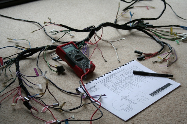
Other issues that, for now, remain unresolved are i) a missing green & brown wire for the reverse light switch and ii) a spare purple & white wire at the centre of the dash. The E-Type forum is very helpful in cases like this as there’s a wealth of knowledge available from the forum members. I was not alone with both the missing and extra wires as one member had decided to use the spare purple & white wire for the reverse light switch. Perhaps I’ll need to do the same.

Feb 192012
 

Two new fans for a Series 2 were ordered from SNG Barratt. However when they arrived they were too large to fit in the radiator cowling. The diameter of the supplied fans was approx. 1″ bigger than the originals. They had sent me fans for an XJS V12, which would explain the incorrect part number being moulded in the fan centre! They looked identical apart from the increased diameter.

So I called Barratts to explain and they said they simply trim them to the correct size. I could either send them back for Barratts to resize or do it myself. I couldn’t be bothered with the hassle of sending them back so decided to do it myself.

6mm ply was used to fabricate templates to trim off the excessIt’s a well-known phenomenon that as soon as the dreaded ‘E’ word is mentioned the cost of parts rocket skyward, to whatever the vendor and, being of a cynical nature, the vendor community think they can get away with. The fans being a case in point. At the time, an XJS fan cost £15 while the E-Type fan cost over £30 – an eye-watering mark up! So it’s worth finding out if a part was common to other models/marques.

The plan to trim off the excess from the fans was to sandwich a fan between two plywood templates. Then run a router around the template so the smooth shaft section of the router bit would butt against the template and the cutting section cut through the excess fan blade below.


Birdfeeder base was an exact diameter match which made making the templates much easierAs luck would have it, the base of a garden birdfeeder had exactly the same diameter as the original fan. So this was used to cut out the templates, using the same method above.

It also became clear as work progressed that the plan was rather over-engineered. All that would be required was a correctly shaped upper template for a section a little wider than the fan blade. A blade could be positioned under this section and trimmed with the router.

A router was then used to cut off the protruding fan bladeThe fan could then be rotated until the next blade was under the same section and process repeated until all the blades had been cut to the correct length and profile. The blade ends were then lightly sanded to remove any remaining swarf and were then ready for fitting.

Feb 182012
 

Unscrewing the two long bolts provides access to the internal components
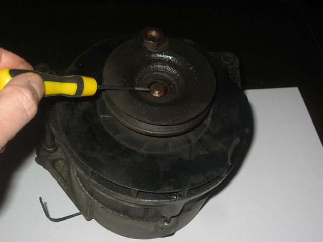
One of the great things I’ve found about the restoration of the various electrical components is that they were designed in an era before our ‘throw away’ society. Therefore overhauling the units is well within the capability of most enthusiasts. As with the fuel pump, the stripping down of the fan motors was very simple.

Having said that, the fans had been attached the wrong way round and no matter what I tried they would not come free. I tried using a small, hub puller type tool on the first fan. However all this achieved was to shear the nylon fan from its central metal fixing, which then had to be carefully cut off using a Dremel tool. So two new fans were added to the ever growing shopping list of parts required!

The fan motor casing consists of a square steel body clamped between two alloy end plates. After the two long screws have been withdrawn, the end plates can be prised from the body with a screw driver. These Lucas motors weren’t designed to be watertight as the rear end plates have openings for the electrical connections. So, over time, water ingress had taken its toll on the interior components.

Rear end plate

Corrosion within!

A rusted armature

A little persuasion was all that was needed to remove the end plate

The internals were fairly rusty ... probably not helped by the openings for the electrical connections in the end plate allowing water in

The armature had suffered worst

As the fan was still attached, the rotor (or armature), the front end plate and fan had to be removed as one. The only other parts within the motor are a wound stator and the armature brushes mounted in a plastic holder. The holder can be withdrawn by removing the two screws on the underside of the motor body.

Wound stator removal

Wound stator & brushes

Stator is just a push fit

Two central screws secure the stator housing

Stator housing can then be removed

The stator removed from the plastic housing

The stator can then be pushed out of the plastic holder. The brushes are loose fitting and can simply be pulled apart and lifted away from the holder. In the end neither fan blade could be removed intact. A Dremel with a cutting disc was needed to remove the metal fixing that remained stubbornly attached to the armature shaft. Once it had been removed the armature and front end plate could be separated.

A thrust washer sits between the front end plate and the armature. A similar washer isn’t necessary between the armature and the rear end plate. When the fan is operating, the fan blade produces a forward force on the armature pushing it towards the front end plate and away from the rear end plate. Therefore there is no load on against the rear end plate.

Thrust washer between the front end plate and the armature