
The pump body and most of the other alloy parts were taken to Carb Clean to be ultrasonically cleaned. I thought this would be better than blasting with a lightly abrasive medium and was pleased with how the parts came out.
 It became apparent that one of the common problems with this SU pump was the tendency for the points to stick, especially on cars stored over winter. After hearing stories of drivers having to use a hammer to whack the pump back into life, I decided it was probably a good idea to upgrade from points to electronic actuation with a kit supplied by Burlen Fuels.
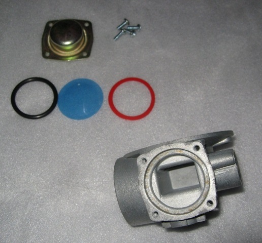
A fuel pump repair kit was also ordered which contains all the various gaskets, non-return valves, diaphragms etc for a full rebuild. Whilst this was not exactly a cost effective choice, with the cost of the parts close to that of a new pump, it was done more out of interest to understand the inner workings of the pump. Most of the parts for the rebuild kit are shown in the picture along with the cleaned pump body and non-return valve clamping plate.
The rebuild of the pump body section was simply the reverse of the steps taken to strip the pump down. The only issue was the orientation of the domed diaphragm in the delivery chamber. I’d taken plenty of photos when dismantling the pump but none of them showed clearly whether the dome should face into the delivery chamber or the cover. The service manual suggested that it should face into the delivery chamber but the diagram also had additional springs and diaphragm plates which were not present on my pump. A quick call to the technical department at Burlen Fuels confirmed that this was the case.
| Delivery Chamber | Inlet Chamber | Pumping Chamber |
|---|---|---|
|
|
|
|


Stating the obvious but the only issue with the installation of the non-return values is to ensure their correct orientation. This can be checked by blowing backward and forwards through the value to determine from which side flow is possible. The only other difference between the two valve assemblies is the presence of a gauze filter on the inlet side.

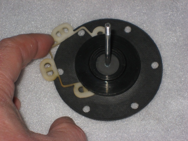 The new armature guides supplied in the repair kit were 5 plastic figures of 8, as shown in the first photo above. The original guide was a single piece and the new guides seemed to be a backwards step rather than an improvement. So the original part was refitted and avoided having to hold five guides in place when refitting the armature/diaphragm into the coil housing.
Next the return spring is placed with the smaller circumference towards the armature. The pump body, armature/diaphragm and coil housing can then be reassembled and secured by 6 screws.
 Converting the pump to electronic actuation requires a magnet carrier to be attached to the upper end of the armature spindle. First a plastic guide tube is pushed over the spindle down into the coil housing. This centralises the spindle movement within the coil housing. The magnet carrier is fully screwed onto the spindle before being backed off until it is aligned to be perpendicular to the line passing through the pedestal mounting holes. It is then secured in this position on the spindle by tightening an allen screw.
 The bakelite pedestal is replace by a PCB which is mounted on spacers to raise it away from the coil housing. On one of the spacer mountings contains a ‘Hall Effect’ fork. The fork enables the electronic circuit to detect the travel of the magnet carrier and thereby control the energising of the coil.
The fuel pump operation can be ‘tuned’ by the rotational positioning of the Hall Effect fork. This is achieved by loosening the screw above the fork and slowly rotating the fork until the pump speed reaches its maximum. The fine tuning would wait until the final testing of the pump when flow rates would be checked.
 At some stage one of the cooling fan motors had been replaced with a round-bodied motor which I think must be from a Series 3, shown on the right. So the first task was to acquire a second motor which is correct for the Series 2. One of the vendors at the Jaguar International Spares day suggested that these occasionally came up on the eBay website.
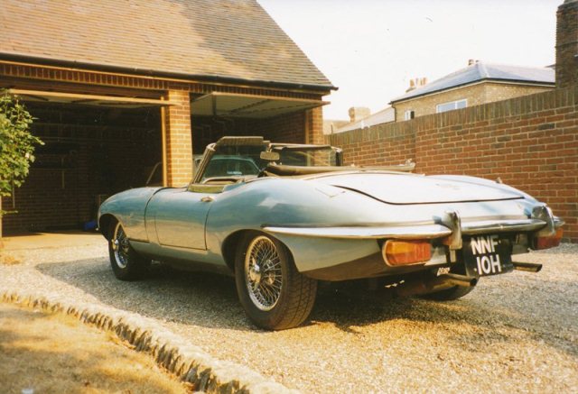
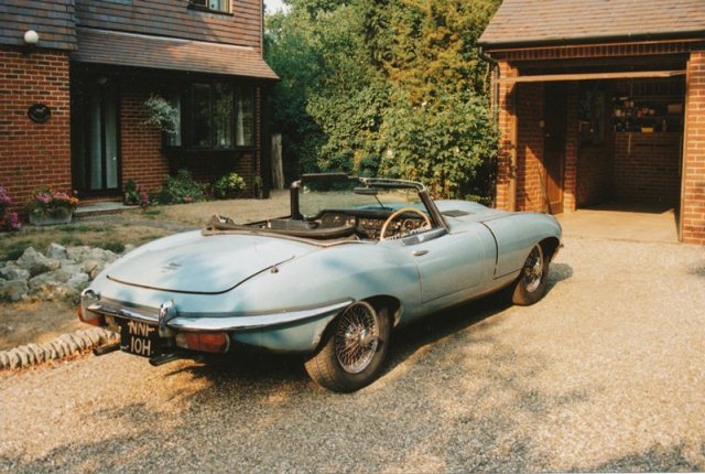
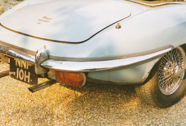
 Oddly, at the end of their advert, they mentioned they were looking to get hold of a boot lid. At some point my car had had a slight shunt at the rear which had twisted the frame under the boot lid’s skin, which is just about visible in the photo. The bodyshop suggested that, although it could be repaired, it would probably cost as much as a new one as the skin would have to be removed to repair the frame.
 The motors were indeed in need of a complete overhaul and for some reason had the white fans mounted back to front. I’m sure this wouldn’t have helped in the efficiency of the cooling and it certainly didn’t help when I came to remove them! Funnily enough, a few days later, an advert appeared on eBay for a basket case restoration of a red roadster, with my blue boot lid! As I said – buyer beware.
 Once removed from the car, the dismantling of the pump is a fairly straight forward process. I started by removing the six screws around the base of the coil housing which allowed the pump body and coil housing to be separated, revealing the diaphragm and pumping chamber.
 The dismantling of the pump body section was completed by removing the inlet and delivery chamber covers. The inlet cover is simply a cork gasket and cover retained by a central bolt and washer. As far as I can tell the inlet chamber smooths the flow of fuel by having an air pocket which can expand or contract according to the pressure in the chamber. Four screws retain the delivery chamber cover under which is an ‘O’ ring, diaphragm and plastic gasket, see photo. Again the chamber provides smoothing of the flow of fuel due to the flexing of the diaphragm.
 The disassembly of the coil housing section was also a simple process. The black plastic end cover was withdrawn once the terminal nut had been undone and the tape sealing the end cover/coil housing join removed. Underneath the cover is the contact point assembly, which consists of a Bakelite pedestal holding the sprung upper contact points and a rocker mechanism holding the lower contact points. A small capacitor is connected between the upper and lower contacts to suppress arching across the points gap as arching causes premature deterioration of the contact points.
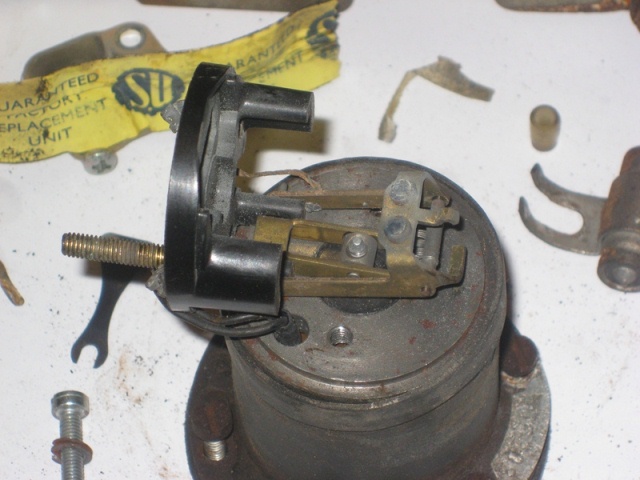 After the two screws had been removed the pedestal could be rotated away from the rocker mechanism. Both the upper and lower contact points were badly corroded. Finally the rocker mechanism and armature & spindle were removed. This can be achieved by disconnecting the leads to the rocker mechanism and then rotating it until free from the spindle. Alternatively the armature/diaphragm can be rotated anticlockwise until the spindle is free of the rocker mechanism.
 When the pump was first removed what appears to be a capacitor (see the photo on the left) was connected across the positive terminal and earth. This part doesn’t appear on the Jaguar parts list so I assume this must have been added at a later stage. As previously mentioned capacitors were used to suppress electrical arching but I’m not sure whether this capacitor was added for this reason or possibly to suppress electrical interference produced when the pump is in operation.


 With the body shell and engine sent away for restoration, attention turned to the refurbishment of the electrical components. The first was the fuel pump which was looking slightly worse for wear and somewhat corroded after 40 plus years.


