Chris

Oct 112012
 

Wiper arm spline drive
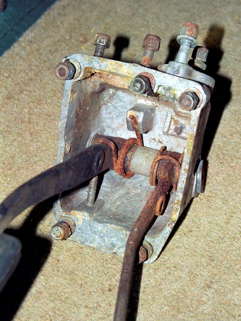
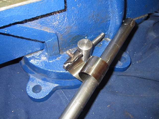
The general consensus from people who have gone through a full rebuild is that one of the first tasks is to fit the various pipes and components within the bulkhead, before access becomes too restricted. So I set to work on the wiper rack. It was working fine but had started to show signs of rust so I decided to smarten it up. Yet again, in my enthusiasm to press on, I forgot to take some decent before photos. The only difficult part during the dismantling was the removal of the rear brackets from the three splined drive assemblies, which needed to be pressed off. The rest of the parts were simply secured by nuts or circlips.

Splined wiper blade drives - the central drive (uppermost) has a spacer between the drive and the rear bracket
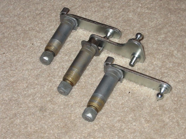
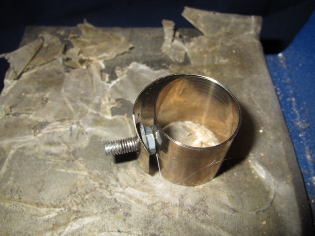
The wiper arm splines on each of the three splined drives weren’t in the best of shape but were still serviceable. Which is just as well as the only replacement I could find was for a fully remanufacturer rack. Due to the shape of the rack, the central drive has a longer shaft than the outer two and so has a spacer fitted between the drive and the rear bracket.

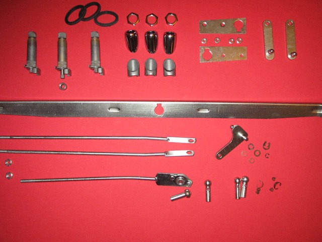
With the exception of the angled bezels and chromed parts, the individual parts followed the now standard cleaning process: immersion in a citric based rust remover overnight, wire brushing, zinc plating/passivation and finally coated with Gtechniq S1. Meanwhile the outer bezels and retaining nuts had been sent off to be chrome plated.

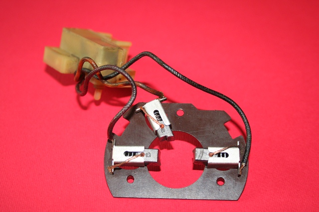
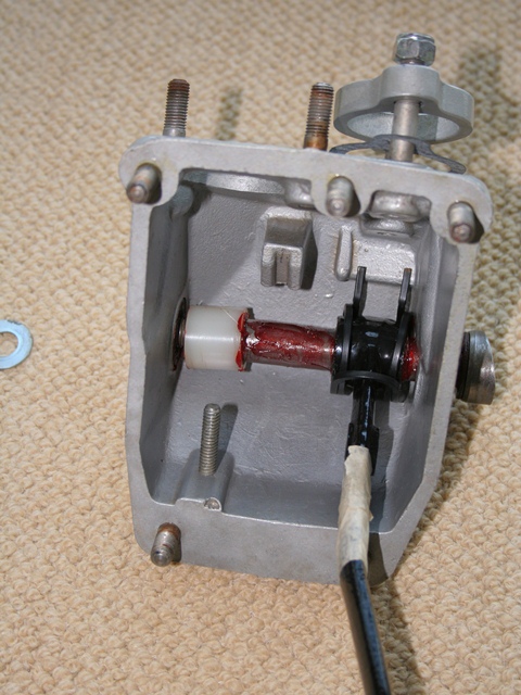
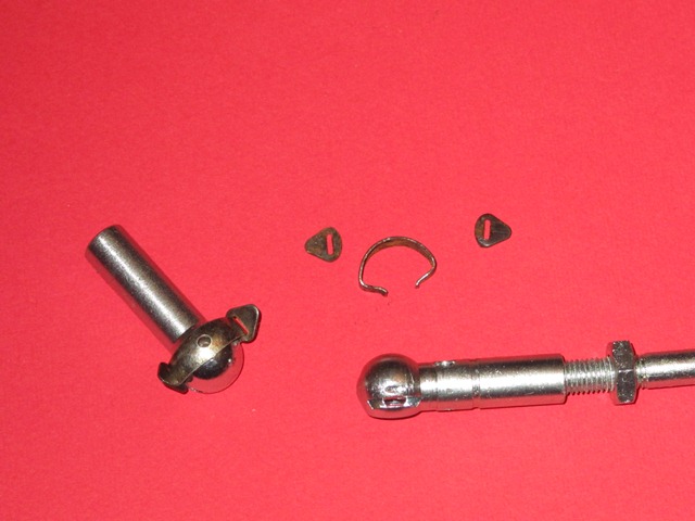
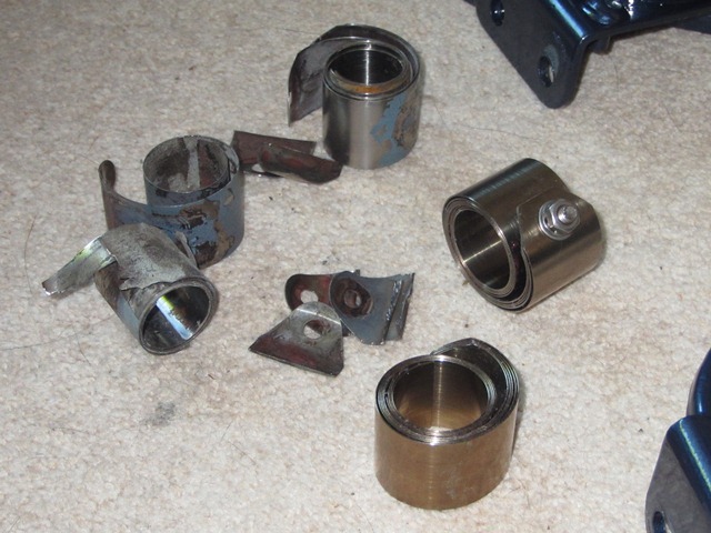
The synchronisation of the rotation of the three splined drives is achieved by two connecting rods, with the central drive also having a connecting rod to the wiper motor to provide the drive. At each rod end is a ball-joint fitting which is secured by a small, horseshoe shaped, snap-lock clip shown below. Unfortunately one of the tiny snap-lock ‘ears’ made a break for freedom and, despite a hands and knees search of the living room carpet, was never to be seen again! The only option available was to purchase a complete socket unit which included the clip and the inevitable robbing by the E-Type parts suppliers!!

Original & new snap-locks Wiper rack components Reassembled splined drives

The original snap-lock clip on the right and the rather expensive complete socket unit, on left

Wiper rack parts plated and chromed, ready for the rebuild

Rear brackets reassembled onto splined drives

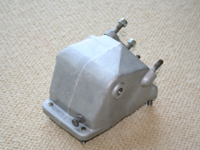
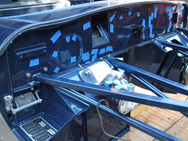
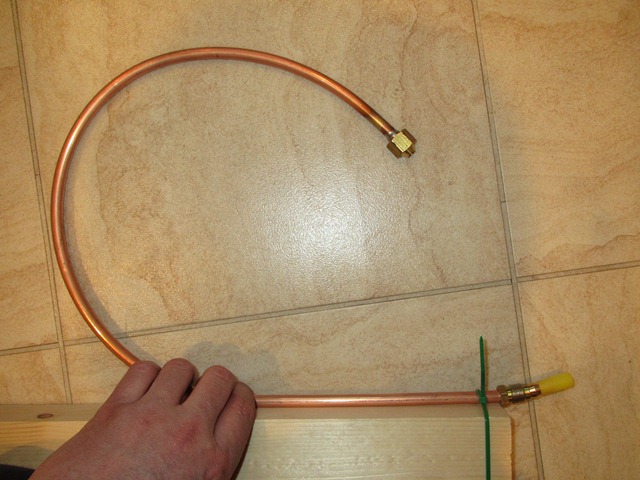
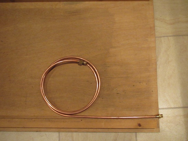
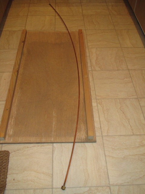
The connecting rods are connected to the central wiper drive by a series of spring washers, nylon guides and secured with a circlip. All very straight forward. All that remains is to fit the rack and connect the central drive to the wiper motor. I think it will be necessary to fit the washer jets and tubing before the rack as there’s not a lot of room in the bulkhead.

Refitting parts order Connecting Rods refitted Completed wiper rack

Sep 072012
 

The first task to complete on the newly returned bodyshell was a thorough rustproofing of all the various cavities. I’d already got a 5 litre tin of waxoyl, so I chose to use this rather Dinitrol, which often has good reviews. I actually ended up using 10 litres as most of the cavities were covered within an inch of their lives!

The rustproofing gun purchased from a local auto factors was a good investment as it had an 18″ flexible nozzle to allow spraying deeper into the various cavities. The general advice is to heat the waxoyl and/or thin with white spirits to help it to flow into all the nooks and crannies. So all that remained was to wait for a suitable, hot, sunny day.

Working front to rear, the areas to be treated were:

  • Bonnet
    • Headlight areas behind the sugar scoops
    • Bonnet Undertray, especially behind air intake lip
    • Bonnet Air Channels
  • Bulkhead
    • Behind bulkhead side panels, via hole either side in engine bay
    • Dash area of bulkhead
    • A-posts
    • Heating vents – not entirely sure whether this will prove to be wise!
  • Cavities accessed from interior
    • Sills – via the three holes in each inner sill
    • Inside of transmission tunnel
    • Doors, especially frame to skin join
    • B posts
    • Closed sections behind seats – which would require access hole to be drilled!!
  • Boot area
    • Inner Rear Wheel Arches
    • Boot floor strengtheners
    • Rear light/number place section
    • Bootlid – the frame and boot skin joint, hidden by frame
  • Miscellaneous
    • Rear Chassis Legs (IRS support brackets)
    • Chassis Floor strengthening sections under car

The rear wheel arches and the bonnet/wing joints will be done with a brush towards the end of the rebuild.

Bulkhead holes were masked to stop overespray covering the entire engine bay! Yet more masking ....

Finally there was a break in the dreadful British summer and decent weather coincided with a free weekend. The various holes in the bulkhead and body were masked in an attempt to limit overspray.

The areas to be drilled for the access holes were masked to stop 
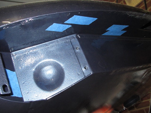
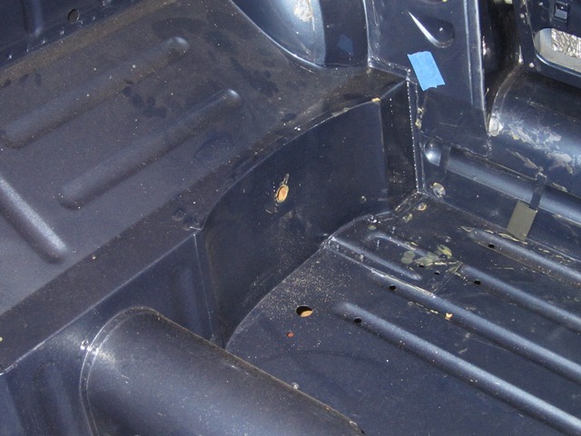
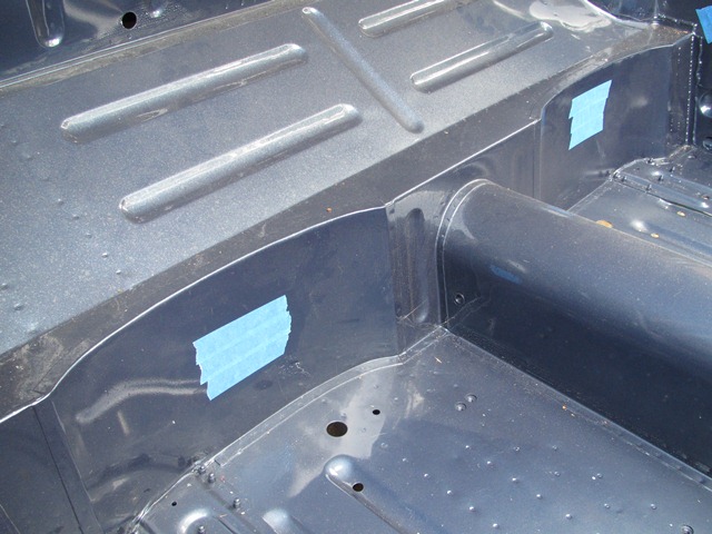
The only problematic cavity is the closed box section in the rear bulkhead, immediately behind the seat bases. I could either leave alone and risk it rusting from within or drill access holes in my lovely painted bodyshell.

Taking others advice from the E-Type forum, I decided it would be better to protect it as the access hole could be plugged with a blanking grommet which would eventually be covered by the interior trim.

The area around the planned access holes was masked to help protect the surrounding area during drilling. A small pilot hole was drilled before using a 19mm core drill bit to cut the final access holes. Fortunately the holes were fairly neat and tidy but I didn’t enjoy drilling my fresh paintwork!

The rustproofing gun and heated waxoyl ready for spraying Closed box sections access holes were drilled to allow the cavity to be rustproofed The headlamp area was given several 'generous' coats of waxoyl, followed by a final coating by brush.

The 5 litre tin of waxoyl had been stored for several years during which time all the solid particles had settled to the bottom. So I emptied the entire tin into a large plastic container and added a small amount of white spirit. It was then heated in a sink of boiling water before being mixed thoroughly using a mixing paddle.

A 2m length of plastic tubing was used to feed the gun with waxoyl. The aim was to give me sufficient reach to get the gun into various cavities without having to continually move the waxoyl container. Fine in theory but far from it in practice!


This caused several problems. The first was that the tube in the waxoyl became soft due to the heat and also appeared to swell (I assume absorbing some of the white spirit). In its softened state it had a tendency to bend sharply, pinching off the supply. This resulted in what can only be described as a backfire causing the waxoyl to be propelled from the container, covering everything in sight!

The second problem was that if spraying was stopped for even a short period, eg moving the container to a new location, then the waxoyl would solidify in the tube. Therefore everything had to be re-heated a number of times.

For the second tin, a shorter length of tube was used and the waxoyl was left in the tin and the tin placed in a container of hot water. This proved to be much more successful.

All that remained was to clean the car as every single panel appeared to have been the victim of the backfiring problem!

Aug 312012
 

The section in the service manual for removing the independent rear suspension (IRS) unit gave the false impression that it was simply a matter of disconnecting the handbrake cable, the hydraulic pipe and prop shaft, undoing the roll bar mounts and knocking off the radius arms. The IRS cage could then be lowered after unbolting the four cage mounts.

It probably is that simple for well maintained cars but mine had seized solid, resulting in bloodied knuckles and much cursing. In fact I couldn’t even get the wire wheels off as they were rusted to the hub splines! The brake connections and prop shaft were fairly easy to undo but everything else was struggle after struggle! The radius arms connect to cup fittings secured to underneath of the floor pan by what look like rivets. However the radius arms had well and truly rusted to the cups. Wooden wedges were hammered in but they still refused to budge.

I later found out from the E-Type forum that they are not rivets but something called Huck bolts, which are designed to shear in the event of an accident. I also found out others’ tricks to release the radius arms from the cups once the retaining bolts have been removed. Too late for my removal but no doubt they’ll be very useful in future. The first is to drive the car slowly backwards and forwards, with the aim that the changing loads breaks the radius arm/cup bond. The second is to chock the rear wheels and then jack up the front creating a load in the radius arms.

I briefly tried applying heat but all this did was burn the rubber bushes, producing acrid smoke. They eventually came free after applying penetrating oil over a period of several weeks and then jumping up and down on the end of a very long lever, inserted between the floor pan and the radius arm. To the untrained eye, the jumping up and down in a frustrated, childish manner while shouting ‘aaaargh!’ might have come across as a method of last resort …. but it worked!

The next setback was the removal of the roll bar. The bolts securing the mounting brackets were also seized but as they angled slightly downwards it wasn’t possible to apply penetrating oil so that it could soak in. Again I tried using localised heat but, like the radius arms, the bushes started to burn. By this time patience was in short supply, so I gave up and ground off the bolt heads to release the roll bar brackets.

The bolts securing the four IRS cage mounts had also rusted but fortunately they could be still undone. The main problem was the confined space so initially they could only be undone a 1/4 of a turn at a time. As I’d been unable to get the wheels off, it was rather an unconventional removal. Wooden blocks were placed under the cage’s base plate and the car raised away from the supported IRS.

The final dismantling of the IRS was equally unconventional for the same reason. The wheels and hubs were removed with the drive shafts and lower wishbones still attached and taken to a local garage so the hubs could be pressed out of the wheels. There was quite a build up of oil on the differential which suggested some of the seals might have perished. Although they’re interchangeable, and I didn’t know at the time, the aluminium hub carriers are not correct for the E-Type, which should have straight rather than sculptured sides.

 Posted by at 8:49 pm
Aug 312012
 

When I first contacted Hutsons, I was warned that they estimated it would be 10 months + before I would get the completed, painted body shell back, such was their current work load. So my aim was to get all the other components completed for its anticipated return in May 2011.

I tend to be rather optimistic (read extremely optimistic!) in the time it will take me to completed things. Even so I knew I wouldn’t be able to tackle everything in that time. The plan was to get the engine and gearbox reconditioned by reputable companies. In the meantime, this would give me the space and time to renovate and restore the other components.

I chose VSE to recondition the engine, based both on recommendations from others and price. I wanted to see their operation first, mainly out of interest, and to discuss the rebuild in person. So I headed off to see them in mid-Wales. It the last place you’d expect to find an engine reconditioning firm – it really was in the middle of nowhere in converted farm buildings with sheep for neighbours!

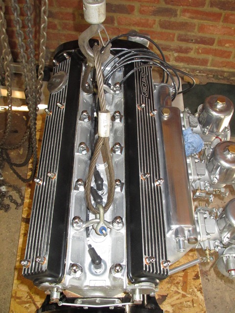
VSE offer a number of performance levels for their rebuilds and those that had recommended them suggested to go for maximum torque rather than headline BHP, which made good sense.

I think it’s all too easy to go over the top seeking greater performance with loony cams and excessively lightened clutch plates at the expense of drivability. So I opted for mildly tweaked performance which is in between their VS1 and VS2 levels, a 123 Electronic Ignition distributor and adapted to accept a modern oil filter.

The first thing to do was to build a suitably sturdy trolley which was low to the ground to avoid the problems encountered during the engine removal. The trolley base was made from two sheets of 22mm wooden boarding with castors that could be bolted directly to the base.

Even this wasn’t strong enough partly because I had used a coarse resin chipboard. Additional sections of wood were attached to the underside to stop it bowing in the middle.

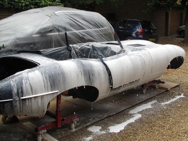
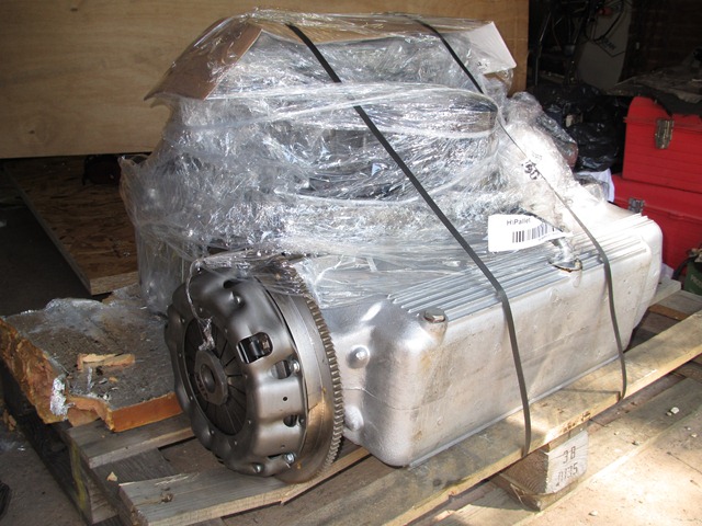
It was far easier to get the engine delivered rather than trek out to mid-Wales again. In due course the engine arrived wrapped in cellophane, strapped to a pallet.

Unfortunately the body shell hadn’t even been started at this point which was annoying. My regret is that, if I’d have know how long it eventually took I’d probably have taken on the rebuild of the engine myself, farming out the machining tasks.

Below are a few more photos of the reconditioned engine, more for interest than anything specific to mention …..

Aug 312012
 

The two tried and tested methods for the engine removal are either lifting it out from above or lowering it onto a trolley and then lifting the body sufficiently until the engine is clear of the sub frames. Although I’ve heard of people, doing full restorations, who have lowered the engine onto a trolley and then removed the surrounding engine sub frames.

The difficulty with the removal from above is that the engine and gearbox come out together as a single unit and this requires it to be tilted at the same time as it is being lifted clear. I didn’t have a controllable method of tilting and wasn’t too keen on having such a weighty item dangling at such a height.

All the ancillaries had been removed and the lifting frame ready to drop the engine. The off-side front suspension still refused to come off!
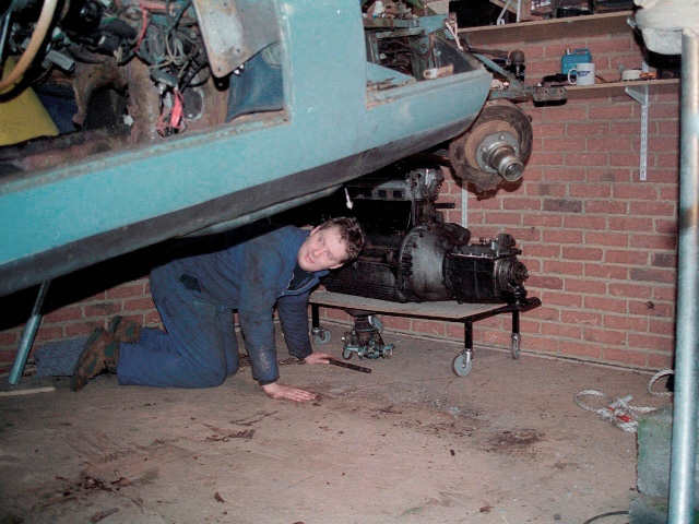
I was also doubtful that my home-made lifting frame, scaffolding cut to make a cross beam supported by A-frames, could raise the engine/gearbox unit to a sufficient height to clear the sub frames. So my only real option was to drop the engine.

The bottom out approach is documented in the Haynes manual and required the removal of all the engine ancillaries, the exhaust and inlet manifolds, alternator, oil filter etc. Once these had been removed I was then ready to lower the engine. Gulp! So far, so good.

At this point I must have taken leave of my senses when making some key decisions and the removal process descended into more of a farce!

I had some 1″ square Dexion speedframe lying around which included a set of castor wheels so I set about making a makeshift trolley. I’d lower the engine and gearbox on to the trolley, lift the car and then pull clear.

The first issues were the length of the 3-pronged corner connectors and that a length of 1″ square would be required between the connector and the castors. This resulted in a considerably higher platform that I’d originally envisaged.

The knock on effect was that, not only would I have to raise the front of the car even further, I would have to raise the rear of the car to reduce the body angle when the front was raised. This would allow the engine & gearbox to be dropped without hitting the sub frames. At this stage I should have reconsidered my approach to how I was dropping the engine.

The car was already supported on axle stands so once the ancillaries had been removed, the hoist could be used to lower the engine onto the waiting trolley. The castors were already showing signs of giving way, as can be seen in the photo above! I really should have reconsidered whether it was wise to continue. However, again, I ploughed on. Dooh!

The ridiculous height of the makeshift trolley caused no end of trouble! Not only that but it shows the first signs of the castors giving way under the weight
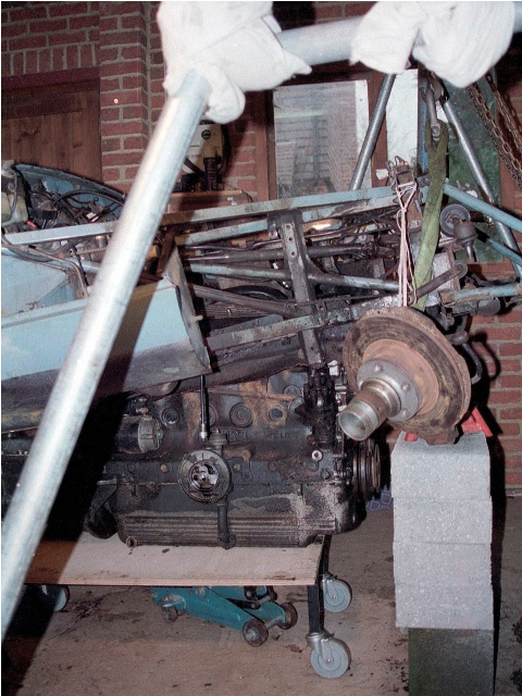
The front and rear were then raised alternately, supported by axle stands on building blocks. The rear was just about within the range of my trolley jacks but the front needed to be lifted via the lifting frame.

Once the front sub-frame was clear of the engine, the lifting frame was used to take the full weight of the front of the bodyshell. The supporting blocks were then removed to provide an exit route for my wobbly trolley. The trolley castors didn’t approve of being moved and their jaunty angle worsened severely as the trolley was delicately pulled clear!

At this stage I would have been in all sorts of problems had the trolley collapsed “mid-extraction” as the only lifting gear I had was in used supporting the bodyshell!

I did have to realign the trolley legs several times, taking the weight by an extended crowbar. It was very close but fortunately the trolley lasted just long enough to pull the engine clear. It was then mounted on a proper engine stand.

On a positive note, the lesson learnt for the rebuild is to use a more substantial trolley which is as low to the ground as possible and to have a backout plan in case something does go wrong. Even with the self-induced problems, I still think dropping the engine is the way to go!

Jul 262012
 

Cooling on the original Series 1 cars was provided by a thin single two bladed cooling fan. This was uprated for the Series 2 with the introduction of twin four bladed fans. One of the popular upgrades is to improve the cooling by installing kits from Kenlowe or Coolcat, which are probably more suited to the stop-starting of today’s congested roads. I’m not sure if this upgrade is more targeted for the S1, so my aim is to restore all three fans, pick the better two for the rebuild and keep the third as a spare. I will then re-evaluate once I’ve driven the car for a period of time.

Motor body prior to shot-blasting
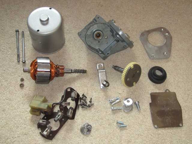
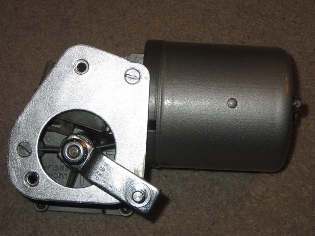
The alloy end plates were sent off to be ultrasonically cleaned while I renovated the motor body and internals. The renovation of the motor bodies ended up being a bit of a palaver and took several goes before I was happy with the end result. They were quite heavily rusted and after shot-blasting revealed quite heavy pitting. Rather optimistically, I thought this would be hidden when they were painted with silver Hammerite. What I soon learnt was that paint is not a good filler as the pitting was still clearly visible through the paint. Also I wasn’t happy with the colour of the silver Hammerite compared with the original finish which was a dark silver grey.All the bodies were quite badly pitted

Unfortunately Hammerite have stopped making the dark silver paint and it took quite a while before I managed to find a suitable equivalent, Rust-oleum paint code 7388.0.4. In the meantime the motor bodies had been shot-blasted again and the pitting filled with Isopon Metalik filler. The first attempt with the Rust-oleum was a disaster. The paint seemed to effervesce on contact, presumably to obtain the hammered effect, but the bubbles created remained in the final finish.

Colour difference between the Hammerite and Rust-oleum ... the wiper motor will now be re-painted to match!
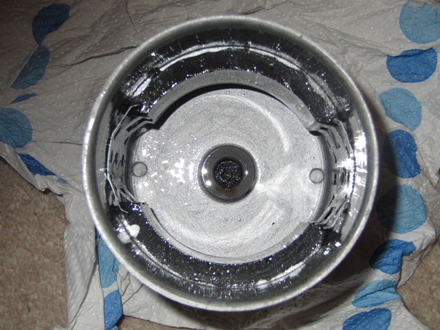
I finally managed to get a reasonable result by heating the spray can in hot water and the motor body in a low oven. This reduced the viscosity of the paint sufficiently to allow the bubbles to burst and then the paint to level sufficiently before it started to ‘skin’.

The photo to the left shows the motor body painted with Rust-oleum compared with the wiper motor painted in silver hammerite. I’ll now re-paint the wiper motor body in the darker grey.

The armatures were next to be tackled. The rusted iron parts forming the electromagnet were carefully wire brushed before being polished. Then Gtechniq S1 Smartmetal was applied to give a hydrophobic coating which hopefully might delay the onset of rusting in future. Finally the copper contacts were polished with good old Brasso, the gaps between the contacts cleaned out and new brush sets obtained, Lucas part BR1 743171.

Before …

and after

New brush sets

Armature condition as removed from the fan motor

Armature after cleaning and polishing

New motor brush sets purchased on eBay

The stator and the various bolts, washers and screws where then zinc-nickel plated using a kit purchased from Gateros Plating. The electroplating is surprisingly simple and good results can easily be achieved. The components were finally ready for the rebuild.

The rebuild process is, to use the overused terminology from Haynes manual, the ‘reverse sequence’ of the dismantling … but in this case it is as simple as that!

Plated stator

Armature refitted

Completed fan motor

The fan mounting brackets and the radiator cowl were originally a black, crinkle finish. Suitable crinkle paint spray cans are readily available but, while researching it, I found out that it’s possible to get a powder coating with a crinkle finish. After the disaster with the Rust-oleum hammered paint, I decided to go down the powder coated route.

However, it appears that the crinkle finish look must have fallen out of favour as I’d contacted almost all the local powder coating firms and none of them stocked it. I was about to give up when I found a small firm who had a small supply tucked away. A few days later and the parts were returned. I do hope that, after all this effort, the fans are up to the job!!

When the cars left the factory there were two plastic shields which covered the opening in the rear end plate for the electrical connections but these were missing. Fortunately SNG Barratt now remanufacturer these but I’m not convinced how effective they will be at keeping water out. I guess they’re better than nothing.

Cooling Fan with plastic shroud

Cooling fans – ready to fit

Before shot of the cooling fans

Fans and cowling restored to their former glory. Fingers crossed they're up to the job!

The before shot of the fans and shrouds

Jun 172012
 

The fuel and brake lines were other items that were to be replaced as a matter of course during the rebuild. I had intended to purchase lengths of piping and make the individual pipes myself. However the cost of decent pipe flaring tools, able to achieve consistently good joints, are considerably more than complete kits.

So I’d purchased a brake kit from Automec, a similar fuel line kit from Hutsons and a pipe bending tool. Both kits were supplied in copper rather than bundy or cunifer which is closer to the original look. So I’ll have to see how they look on the car and I may revert to fabricating my own in cunifer; an alloy of Copper (Cu), Nickel (Ni) and Iron (Fe).

More importantly, I subsequently found out that copper brake pipes are banned in countries like Australia and the US, where cunifer is the norm. Apparently the copper pipes are susceptible to work hardening over time which can lead to fracturing. The introduction of Nickel and Iron addresses this problem. I think more research is needed especially as it’s a safety issue.

Back to the pipes … the problem with the kits is that they are fabricated from coiled piping. In order to get neat, straight pipe runs they need to be straightened before forming into the correct shapes.

I found an article on an American car site with a rather over-engineered process for straightening coiled fuel pipes. I had a spare afternoon so I thought I’d give it a go. The main point is that the coiled fuel pipe should only be straightened/bent in the same plane as the direction of the original coil.

The first step is to lay the coiled pipes on a flat surface and uncoil them against a straight edge, therefore ensuring additional bends in other planes are not introduced. Once released, the pipes will spring back to some extent in the direction of the original coil so the pipes will now form an arc.

Trial run with the shorter engine bay 5/16″ fuel pipe

Long boot to engine bay 5/16″ fuel pipe

The second step involves deforming the pipes beyond a straight line so that this time, when they spring back, they (hopefully) return to a straight pipe. As it happens, the pipes need to be bent beyond the straight line to exactly the same radius as the arc of the now uncoiled pipe.

I used two pieces of old shelving and some 9mm cladding, the latter would act as channel down the centre of the form. I guess you could just use one board against a flat surface.

The radius of this arc is determined by the pipe thickness and the diameter of the original coil. Therefore, for a given pipe size from the same original coiled length, the arc radius will be the same regardless of pipe length.

The final step is bending the arced pipes over the form. Starting at one end, position the pipe arcing away from the form but in the same plane. Then bend the pipe around to produce a straight pipe when released. However be careful not to allow the pipes to rotate when doing the final step.

I thought the results were quite good for a pleasant afternoon spent taking a sledgehammer to crack a nut!

Jun 142012
 

It’s fairly common for the bootlid springs to wear and eventually fail. Mine were certainly no exception and the bootlid had never sprung open of its own accord. Each spring should consist of a pack of five leaves but the majority had worn so thin that they’d sheared in two. Hence the lid’s unwillingness to open.

I’d read Eric Capron’s very useful article on replacing the bootlid springs and so it was a job I really wasn’t looking forward to! I’d been meaning to ask Hutsons to do this before they returned the painted bodyshell but, in the excitement of finally having the car returned, I forgot to mention it.

As well as a variety of implements to prise open and hold the leaves apart, it’s a jolly good idea to use some heavy duty protective gloves. Once several leaves have been added the spring force is quite strong and the leaf edges sharp enough to do serious mischief to any fingers left in the way.

The first task in constructing the spring packs is to get the 3/16″ bolt on to the first leaf. I deviated from Eric’s guide as I found it wasn’t that easy to open the leaf sufficiently to insert the bolt with the leaf clamped in the vice. This was partly due to the fact that the vice really needed to be clamped securely to a bench rather than free standing, which made the whole process far more difficult.

To start each leaf, the outer end was pushed until there was just a sufficient gap to insert a flat-bladed screwdriver. The screwdriver could then be turned through 90 degrees, lifting the leaf end away further. This allowed it to be slid over the vice’s swivel lever and the screwdriver removed, see the photos below. A solid bar passed through the centre of the leaf could then be pivoted on the vice body to prise it open. The other end of the swivel lever was hard against the vice body so that it couldn’t rotate.

First leaf : this only needs to be opened sufficiently to insert the washer and bolt. This was quite fiddly and would have benefit from a second pair of hands.

A screw driver was used to prise away the leaf end Inserting the bolt was very fiddly With the bolt in place, the remaining springs can be added to complete the spring pack

Remaining 4 Leaf Springs
The spring pack is completed by adding the remaining leaf springs in a similar manner, one by one. A new leaf was opened as before and placed on the vice swivel lever so that it could be prised open using the bar. This time the leaf needs to be prised open much further so the whole of the first leaf can be inserted and the bolt end passed through the hole in the new leaf … it’s much more fiddly than it sounds!

Once inserted, ease the pressure on the bar allowing until it can be removed. It’s a very good idea to loosely fit a retaining nut at this point otherwise the new leaf is likely to slip off the bolt. Now put the bar through the first leaf and prise open. In doing so, the new leaf will also open and finally pop into place. The process is then repeated until all five springs have been added.

If was a surprisingly fiddly job but I suspect the hardest part will be fitting them to the boot hinges. I’ll put that off as long as i can!

Apr 242012
 

As with all the other electrical units, the alloy parts were was ultrasonically cleaned and then sprayed with Gtechniq S1 SmartMetal while the other steel parts were zinc-nickel plated. The next two tasks were to sort out the gearbox lid which had been distorted and also to strip and paint the yoke.

The offending motor gearbox lid after several attempts at heat shrinking
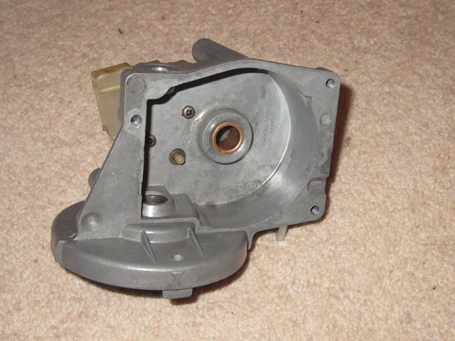
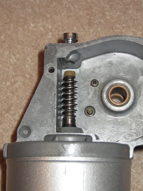
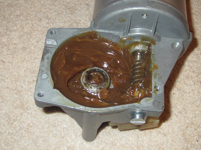
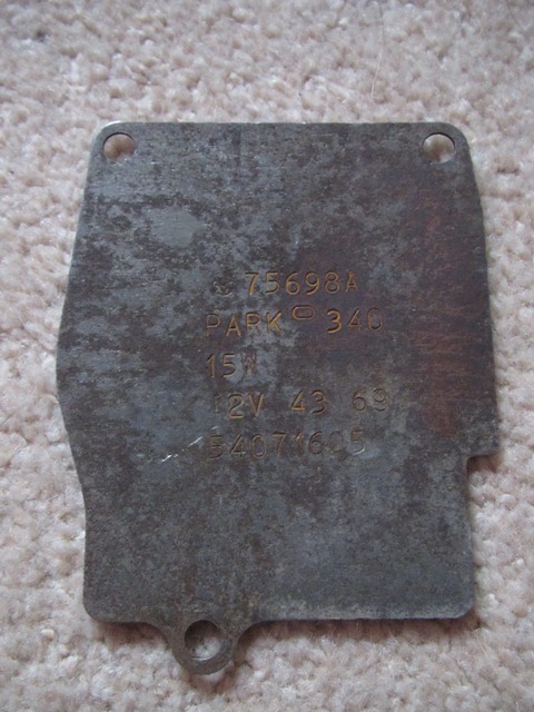
The centre area of the gearbox lid has been stretched at some point. Therefore its outer perimeter no longer made a continuous seal and so would allow water into the gearbox housing.

The suggested solution was to heat shrink the centre section of the lid to reverse the deformation – heating the centre of the lid to near red heat and then rapidly cooling. After several attempts of heating the lid with a gas blow torch and cooling using a can of compressed CO2, all I succeeded in doing was to work harden it in exactly the same shape as before. Aaaaaaargh!

It probably needs to be heated to a much higher temperature using oxy acetylene. In the end I cheated to avoid holding up the rebuild and obtained a replacement lid. When I get time I’ll give it a proper go at flattening the lid, as I would like to keep the original with the correct stampings.

The wiper motor yoke painted in silver hammerite .... at some point I'll repaint in the correct colour
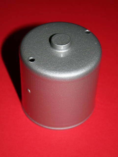
Next up was the yoke which contains the two permanent magnets. The magnets can be removed by lifting the retaining clips so the yoke could then be shot blasted before being painted in silver hammerite. I was quite pleased with the finished article even though the silver hammerite was not quite the correct colour.

During the refurbishing of the cooling fan motors I had found a dark silver hammered paint from Rust-oleum, which is very similar to the orginal colour. At some stage I will re-paint the round bodied yoke but decided to put it off for now. Mainly because of the difficulty I’d had getting a good finish with the Rust-oleum product.

Fortunately the armature wasn’t in such a bad state as those in the cooling fan motors and so all that was required was some light wire brushing and polishing before the S1 SmartMetal coating. I had investigated the availability of new brushes and parking switch units but these seemed to be rather difficult to get hold of. Therefore when I spotted a ‘new, old stock’ brush unit for sale I thought I’d get it as a spare for the future. However I’ve not yet found anyone who can supply the parking switch units.

Cleaned armature Triple Brushes Wiper Motor Parts

The armature was wired brushed to remove the worse of the rust. It was then polished and finally sprayed with Gtechniq S1

The armature brushes and parking switch unit

The wiper motor compentent ready for the rebuild, including the spare armature brushes unit

The rebuild starts with installing the armature brushes and parking switch unit, as these are wired together. The brushes are secured by three small setscrews and the connecting wiring passes through a notch in the motor gearbox housing.

The parking switch is secured by two setscrews from the inside of the gearbox compartment, as shown in the middle photo below. This also shows the protruding parking switch plunger which is activated by a cam on the underside of the gear wheel. The cam positioning is such that it operates the switch when the wiper blades return to their normal rest position.

First fit the brushes Parking switch attachment ACF50 applied to Yoke

The brushes and the parking switch unit are the first to be fitted

The parking switch is attached by two setscrews from inside the gearbox housing. Note the switch plunge which operates when the wipers return to their normal rest position

The interior of the yoke was sprayed with ACF50 which provides a good protection from moisture

After several attempts at fitting the armature and yoke, I found it easier to first fit the armature into the brushes and motor gearbox and then fit the yoke. With this approach its was necessary to hold the armature’s worm drive from within the gearbox so that, when fitting the yoke, the yoke’s magnets didn’t pull the armature out of the brushes. Also don’t do what I did and forget to fit the plain washer between the armature and motor gearbox housing!

Care was also needed in making sure that the thrust and fibre washers were correctly seated in the yoke bearing housing. The easiest way to do this was to join the two with yoke positioned so the ‘bearing’ housing was facing downwards.

Initially I tried to put the armature into the yoke and then attach them both to the motor gearbox. However the problem was it was then difficult to withdraw the three sprung brushes at the same time as inserting the armature, because the yoke restricted access to the brushes.

The middle photo below shows the arrow head marking on the motor gearbox and a corresponding line on the yoke. These need to be aligned when refitting. Also shown is the threaded armature stop. This was then screwed into the gearbox housing until it touched the nylon cap on the armature shaft, before being backed off a 1/4 of a turn.

Next fit the armature Alignment markings Belleville washer goes here

The brushes were then withdrawn to allow the armature to be inserted

The markings on the motor gearbox housing and the yoke must be aligned when re-fitting

The Belleville washer provides pre-load for the armature shaft

The Belleville washers is then positioned within the gearbox before inserting the geared output shaft. The rest of the gearbox was then filled with grease before the output rotatry link and gearbox lid were refitted. The rubber moulding sealing the output shaft area had hardened and split.

At the time I dismantled the motor, it was one of the few parts that wasn’t being remanufactured. Probably because it was only used on the Series 2. However by the time I has started the rebuild, one of the suppliers had made a small batch so I decided to grab one while still available.

Re-packed with grease Output rotary link Motor rebuild completed!

The geared output shaft (just about visible) was inserted and then the remaining space packed with grease

The output rotry link was refitted which also secures the geared output shaft. Although I'd forgotten to insert the rubber seal first .... so I'll have to refit it

The completed wiper motor

The only thing that remains is to adjust the various wiper motor & rack linkages which can only be done once they’re installed in the car. People usually leave the installation of the windscreen until the latter stages of a rebuild. I guess this is because it would restrict access to dash area. However I’m tempted to install the windscreen as soon as the dash wiring looms and dash panels are in place. Therefore I’ll be able to adjust the linkages before the bulkhead access become restricted.

Apr 242012
 

I was surprised how rusty the clutch pedal and pedal springs were seeing it’s inside the car and underneath the aluminium pedalbox housing. I’m assuming this must have been as a result of condensation. Once it’s complete I’ll give the inside a covering of ACF50 to give it some protection. There’s nothing worth noting on the dismantling as the pedals simply rotate on a shaft through the pedalbox.

The pedalbox was renovated before I’d come across the company that ultrasonically cleans alloy components, so it was shotblasted and then coated with a lacquer product sold by Eastwood to stop surface oxidisation. The pedal arm, foot pads and springs were also shot blasted and then powder coated.

The rebuild was fiddly mainly because the pedal springs are quite strong so it’s difficult to align everything while pushing the shaft into position. The final washer had a tendency to drop out at the final moment! It made sense to cover the shaft and mating surfaces in plenty of grease.

I was surprised that the brake light switch is actually part of the hydraulic system, actuated by hydraulic pressure when the brake pedal is pressed. Some have reported problems with the response of this switch and have therefore either replaced it or supplemented it with a mechanical microswitch operated by the brake pedal.

While the car is apart and the looms are being put in place, it makes sense to install both a hydraulic switch and a microswitch in parallel, to build in redundancy. All it would require would be to fabricate a bracket to hold a microswitch in the pedalbox housing. I’ll do this as part of the final electric fitting when the lights are installed.