Chris

Repairing the plenum chamber

 Air Filter  Comments Off on Repairing the plenum chamber
Sep 062013
 

Ropey would be an understatement when describing the plenum chamber. It appears that it was manufactured by bonding two halves together as, once the superficial layers of dirt were removed, cracks were found along the joining lip between the top and bottom halves.

Also, for some unknown reason, a previous owner had drilled a 3/4″ hole in the underside and, looking at it, presumably while blindfolded.

The first thing to do was to remove all the grime and paint in order to make repairs. I was a little bit apprehensive about using strong paint strippers such as Nitromors as I’d heard it damaged fibreglass. Then someone recommended using Fairy Power Spray – I think it’s one of their oven cleaning liquids!

I must admit I was rather sceptical to sat the least. Still, the oven needed cleaning, so if it didn’t work, it wouldn’t be wasted! To my amazement it acted as a very mild paint stripper. Whereas the paint starts to bubble up within a second or two with Nitromors, the Fairy stuff took 5-10 minutes and needed 5-6 applications to remove all the paint.

I guess it shouldn’t have been too much of a surprise as it is designed to cut through oil and grease. The original paint would have been oil based and presumably traces of oil are retained even once the paint has dried.

The air intake brackets were drilled out to provide better access for the repairs or, probably more truthfully, a case of shipwright’s disease. At some stage the brackets must have been painted silver as underneath and in areas that were not visible they were painted black.

I decided to make a fibreglass repair rather than just use filler. The main reason was an attempt to strengthen the join where the two halves had started to come apart, at each side of the opening. The repair sections were built up with three layers of fibreglass which should be sufficient. The mystery hole was also covered over at the same time.

It was then just a case of filling all the various cracks, chips and the repaired hole with Isopon filler before spraying the plenum and air intake bracket with numerous coats of silver Hammerite.

One thing I’ve found with Hammerite paint from painting the wiper motor housing, is that it takes many months to fully harden. Even though it’s dry enough to handle, it’s still quite easy to damage the soft finish for quite some time. Overall I was quite pleased with the end result.

A milestone is reached – back on 4 wheels … almost!!

 Front Suspension  Comments Off on A milestone is reached – back on 4 wheels … almost!!
Sep 042013
 

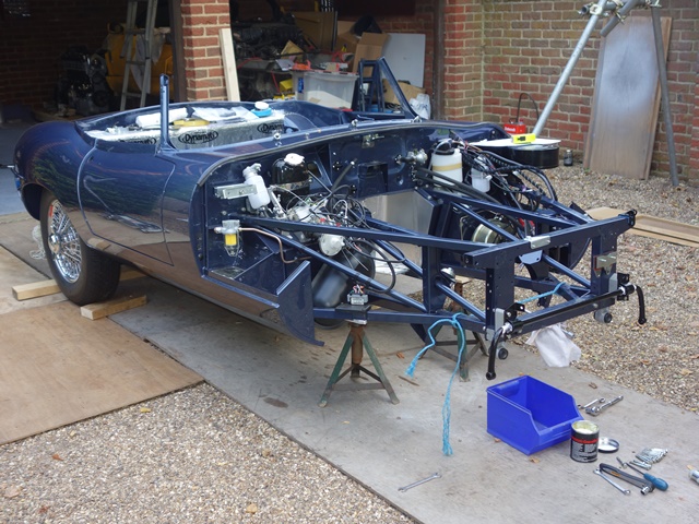
The issues getting the rear suspension fitted meant that there wasn’t time to fit the front suspension let alone the engine.

The front frames were removed to fit the tiny radiator support brackets. As the frame bolts pass through the front suspension mounts, these and the roll bar were refitted at the same time as the frames.

I must mention to Andy at Hutsons that it would be a good idea to fit the radiator brackets on S2 cars before bodyshells are returned to customers.

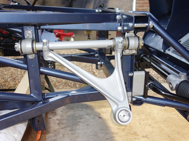
I started with the easier upper wishbones and found the castellation nuts need to be fully tightened to compress the rubber bushes. This pulls the front and rear fulcrum mounts together so the bolts holes line up.

The original camber shims had been re-plated and were fitted behind the front and rear mounts. I suspect the shimming will need to be changed when the geometry is finally set up because the new engine frames have been fitted.

At least it should be a good starting point. The rear mounts also have a strengthening plate fitted on the reverse side on the engine frame, under the nuts. One of these was missing so I suspect at some point the suspension had been dismantled and they’d forgotten to refit it.

The castellation nuts were then backed off as they should only be fully tightened once the full weight of the car is supported by the suspension to avoid damaging the rubber bushes. The wishbone pinch bolts were also not tightened as the fulcrum shaft will need to be rotated during the final setup to set the castor angle.

The upper wishbones were fairly easy to install as they simply bolt on The lower wishbones were much harder as both the front and rear mounts need slotting into the engine frame

For now the aim is to get the car back on four wheels so it can be moved around more safely. The front suspension can only be completed once the engine has been installed when the torsion bars are fitted. This will require the upper ball and steering arm joints to be separated. So at this stage, only the lower ball joint was fully tightened. Without the torsion bars the car should just settle on the shock absorber bump stops.

The moment had arrived. The lowering of the car back on to its own four wheels. Something that hadn’t happened for many, many years. The trolley jack was lowered very gently …. touch down (pats on back etc) …. then lower …. and lower …. and lower …. and so it carried on. I had to close the bonnet and control the jack from underneath but I was getting worried that the bump stops wouldn’t be reached. Do they even have bump stops?!

Will the bump stops ever be reached? ..... No! The car had to be put back onto the axle trolley.

The trolley jack finally reached it’s lowest height so I had to revert to Plan B – back on to the axle trolley until the engine and torsion bars are fitted. Ho hum …. a FAIL! I really should have just measured the compressed shock absorber length when it was off the car and then done some simple Maths. Another lesson learnt!

Bonnet storage

 Miscellaneous Ramblings  Comments Off on Bonnet storage
Sep 022013
 

One of the main problems during the rebuild was the lack of space to store the bonnet out of harms way. It was therefore safer to kept the bonnet on the car and only remove it when absolutely necessary.

It made the fitting of some of the engine bay components slightly more tricky although my limbo-dancing skills have improved no end!

When I was visiting Hutsons, I noticed how they had stored a bonnet while it was off the car. At the front they’d used a steel bar through the eyes of the hinges and then supported the bar on axle stands. Lengths of angled steel were bolted in place of the side bonnet catches to support the rear.

This seemed an ideal solution for the temporary storage of the bonnet and would no doubt be useful in the future. I had some left over ‘L’ shaped stock fence supports so cut these down to size for the rear support legs and purchased a metre length of 3/8″ steel bar.

To give it more rigidity a length of timber was drilled to slot over the support legs. The steel bar is a bit too thin and needs the axle stands to be place adjacent to the hinges to avoid it bending. At some stage I’ll replace it with a 5/8″ bar.

Handbrake rebuild

 Brakes  Comments Off on Handbrake rebuild
Sep 022013
 

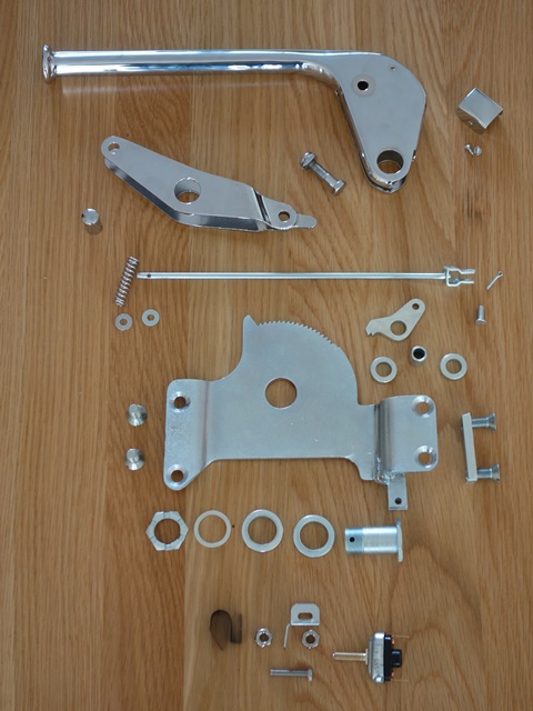
The re-plated handbrake component ready for assemblyThe handbrake had been sent off to ACF Howells for re-chroming as a complete unit. With hindsight it would probably have been better to dismantle it myself and just send them the pieces that needed re-chroming.

I therefore had to work out how the pieces should go back together. The original fittings for the handbrake light switch were missing from the car so the replacement parts would also be added to the puzzle.

Fortunately most of it is fairly self-explanatory. The only issue was having to cut down a roll pin to replace the retaining pin for the push button which wasn’t in the parts returned after re-chroming.

The first task is to reunite the push button operating rod and the pawl of the ratchet mechanism within the handbrake arm. The operating rod is fed through the access hole at the rear of the arm and the pawl is inserted up through the base of the arm, complete with its distance tube and a spacer either side.

Orientation of the operating rod & pawl A clevis pin connects the rod & pawl

The pawl needs to be orientated with the hole for the clevis pin rearward so the hole and fork end of the rod can be manoeuvred to protrude through the access hole in the arm. The clevis pin can then be inserted and secured with the split pin.

The push button needs to be fitted before the pawl pivot bolt, otherwise there’s not enough clearence to insert the retaining pin. Without the bolt, the operating rod can be pushed down the handbrake arm until the hole for the retaining pin is clear of the handbrake arm.

At rest the pawl is held in the locking position by a spring which is inserted onto the operating rod before the push button is fitted. The order of fitting is a washer (not shown in the photo) which sits against protrusions inside the handbrake arm, the spring, a retaining washer and then the push button.

Sprung push button components Roll pin inserted to secure button
The operating rod needs to pushed so it protrudes beyond the end of the handbrake arm (further than in the photo!) so the retaining pin can be inserted Copious amounts of grease was applied before the roll pon was hammered home

A forum member had a thin rubber washer between the second washer and the button. As a rubber washer wasn’t in the returned parts, I can’t be sure if my handbrake originally had one. When the button is fitted the spring is already under compression, providing a cushioning effect and wear isn’t an issue. Therefore I didn’t feel the need to fabricate a rubber washer.

Next the ratchet gear needs to be inserted into base of the handbrake arm followed by fitting the outer cable attachment bracket. Similar to the pawl, the ratchet gear uses two spacers to fill the internal space within the handbrake arm.

The two bolts securing the outer bracket can then be fitted. One acts as the pivot point for the pawl and the other as the pivot for handbrake arm in relation to the ratchet gear.

The final piece in the puzzle was the fitting of the handbrake warning light switch. As mentioned, these parts were missing and so replacement parts were ordered from SNG Barratt.

It looked fairly obvious how things went together. A bracket mounts the switch to the base of the handbrake ratchet gear and it appears that a ‘S’ shaped spring attaches to the end of the switch.

When the handbrake is fully released, a ‘finger’ protrusion at the bottom of the outer cable attachment bracket presses against the spring, which in turn depresses the Push-to-Break switch.

The parts manual indicates two nuts are needed to secure both the spring and the switch. I’m obviously missing something as I can only see how to get it to work using three nuts – one to secure the switch to the bracket and two half nuts to lock the spring at the correct distance from the activating ‘finger’.

Trial fitting the exhaust

 Exhaust  Comments Off on Trial fitting the exhaust
Aug 242013
 

The exhaust system is another area where there are a plethora of options available and with them, opinions on which is best. These range from a standard bore with cast manifolds through to straight through, big bore pipes with either long or short tubular manifolds and all combinations in between. Advice often just reflected what the owner had decided to put on their car rather than comparative tests.
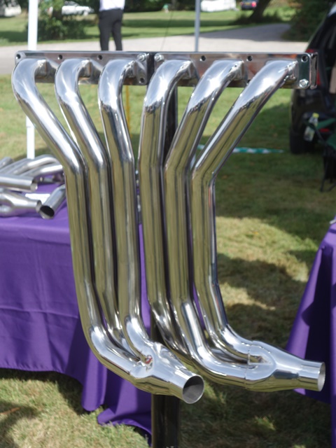
The Classic Fabs long tubular manifoldsIt was tempting to go for one of the tubular manifold systems from companies like Classic Fabs, which are a work of art.

However the administrator of the E-Type forum had done a fair amount of research backed up by practical experience, having fitted most of the different types available.

The general consensus from the forum discussion was that the original cast iron manifolds were very well designed; providing optimised gas flow to speed up the exhaust gases therefore improving low down torque but also heat management. The larger bore systems, specifically when used for the secondary pipes, can result in a torque dip lower down in the rev range.

The other issues are that they are more prone to grounding and tubular manifolds generally radiate far more heat which is then likely to cause other problems, such as brake issues due to the proximity of the brake servo and blistering of the paint work.
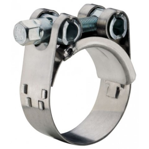
The Mikalor style clamps were used instead of the typical U clampsIt therefore seemed sensible to stick to the standard cast iron manifolds and 1.75″ bore system, which was purchased from PD Gough based in Nottingham.

I’d also decided to deviate from the original look at the rear after seeing others who had successfully avoided the slab-like appearance by removing the rear, brushed aluminium panel. The car will be fitted with a long rather than square number plate which enables straight exhaust resonators to be fitted instead of the standard S2 splayed ones.

The final decision to make was whether to have the system made in mild steel or stainless steel. Apparently mild steel gives a much nicer exhaust note but in the end I went for stainless for longevity. Another recommendation that I also adopted was to fit Mikalor style clamps as they apply the clamping force more evenly and avoid distorting the pipe joints.

Some ‘reject’ manifolds were picked up quite cheaply at the SNG Barratt open day – they had some tiny imperfections in the vitreous enamel finish which I still struggle to find. This finish was never very robust and had a tendency to crack and flake off. So I’m expecting it won’t last too long and will need to be removed in order to paint/treat the manifolds.

The engine installation weekend was fast approaching so I decided to trial fit the exhaust system. At this stage, without the engine in place, all that could be trial fitted was from the muffler section backwards.

The combination of not having the down pipes installed and the car being on axle trolleys meant it was extremely difficult to build the exhaust on the car. The pipe ends were unblemished so the system clearly hadn’t be bench fitted when it was manufactured. Therefore all the joints were still very tight even with a generous coating of Copperslip.

It was necessary to build the system off the car to have any chance of aligning the brackets on the intermediate pipes and to push the resonator pipes fully home to be able to mount them onto the rear hanger.

It was then fitted as a single unit, first fitting the muffler section to the four rubber mounts fixed along the chassis rails. I was struggling underneath the car trying to hold up the exhaust up to the mounts while feeling for the 1/2″ spanner that I’d dropped when I noticed I had an audience – a metre long grass snake was observing my progress a couple of feet away. I assume having taken refuge from the hot, sunny weather.

Mounted centre muffler section My new helper! Resonator pipes mounted at rear
The muffler section fitted fine .... until the resonator pipe were mounted which caused it to rise at the rear A grass snake had sought shelter from the hot, sunny weather The resonators had to be pushed upward with a fair amount of force in order to attach to the rear mount

The connecting brackets between the intermediate pipes and the resonators were all fixed so the whole exhaust was now quite rigid. The muffler section was already mounted but the resonators needed a reasonable amount of effort to push them up to reach the rear exhaust hanger. In doing so, it caused the muffler section to raise significantly at the rear so the output pipes hit the rear floor stiffener.
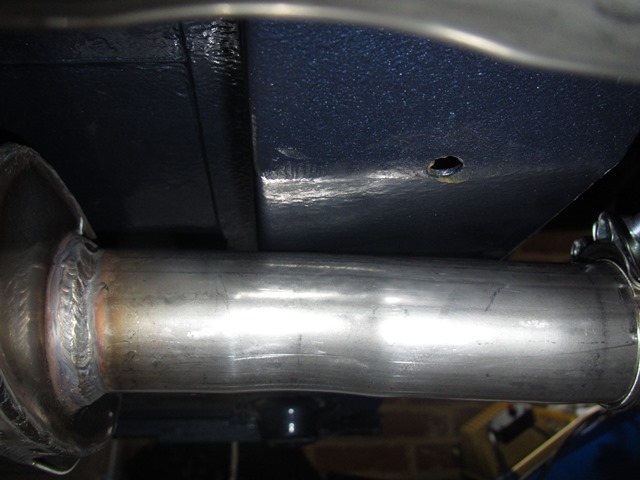
The output pipes from the muffler section foul the rear floor stiffener so something's amissIt didn’t seem right because the small rubber mount at the rear would be under considerably more stress than just supporting the exhaust’s weight. Apart from varying how much overlap there is in each joint, there is no other scope for adjustment and the geometry is fixed so, without modification, the pipes would almost certainly foul the rear floor stiffener.

I emailed PD Gough with the photos above explaining the issues I was having and the purpose of the trial fit was to ensure it fitted correctly before the engine installation weekend. I didn’t want to find out it didn’t fit during the installation weekend and therefore stop the testing of the engine.

I felt their response was more of a fob off and so wasn’t too impressed – “they’d never had any fitting issues before and would be surprised if I had fitting problems once the front pipe are fitted as they would generally bring the system into alignment”.

Personally I’m not convinced because the front pipes are flexible and so their ability to bring the whole exhaust into alignment would be limited. Also the forcing of the muffler section towards the horizontal to stop the clearance issue will only add to the stress on the rear rubber mount.

I’m going to be extremely annoyed if I end up having to ‘surprise’ them by informing them it doesn’t fit.

Installing the IRS – it’s only a matter of 8 bolts …

 Rear Suspension  Comments Off on Installing the IRS – it’s only a matter of 8 bolts …
Aug 232013
 

I had been waiting on the completion of the front suspension components so that everything would be in place to transform it from a bodyshell to a rolling chassis; installing the front & rear suspension as well as the engine over a weekend. I even dared think we might be able to have a stab at starting the engine.

I had read and re-read all the available manuals a number of times to produce a detailed list of tasks that needed to be completed prior to and over the installation weekend.

Adapting the IRS trolley to fit under the IRS cage and raising the platform heightThe first task was to adapt the original IRS trolley I’d made; reducing its footprint to a little larger than the base plate of the IRS cage so it wouldn’t get in the way during installation, giving it sufficient ground clearance to allow the trolley jack to be inserted underneath and raising the height of the cage so the wheels could be put on while on the trolley.

I’m not sure about the need for the latter but it made sense at the time! The aim was to be able to lift the IRS and trolley to meet the chassis.

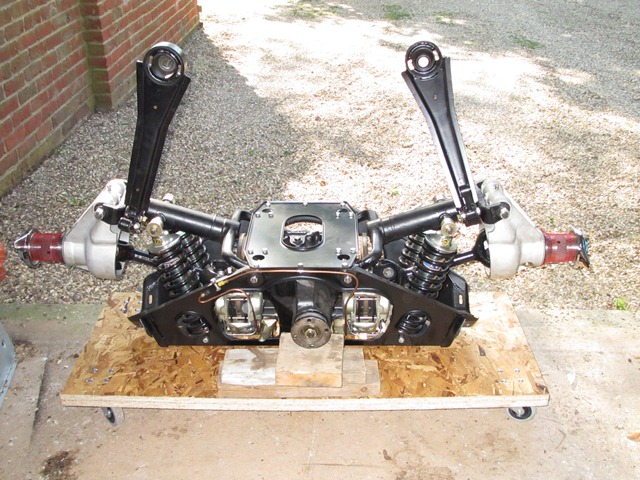
A number of other tasks before the weekend involved the IRS unit which had been sat on its trolley for over a year. Even though it was dry stored, the caliper plating had already deteriorated in this time. These were removed and painted in a tough, silver caliper paint and a remote bleed kit fitted.

The IRS cage had also picked up a variety of scuff marks when it had been delivered and moved around. It was therefore given three coats of 2 pack black paint and two clear satin coats. I didn’t have the luxury of a spray booth so boards and boxes were used in an attempt to keep bugs and leaves off while it dried.

Masking up on the smaller trolley Attempt to keep bugs off Re-painted – not much different!

The planning was finally over and the installation weekend had arrived. Much needed help was drafted in, John had been granted a pass for the dereliction of parental duties who then managed to persuade Martin to travel down to complete the line up. Both had ample engineering knowledge to complement my tea making skills!

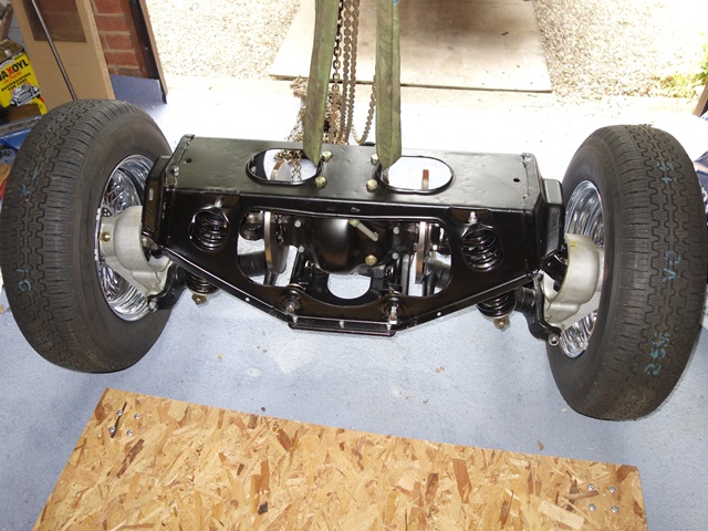
Four Metalastik mounts connect the corners of the rear suspension cage to the chassis. Restricted access during the fitting the IRS unit is overcome by pre-fitting the rear mounts to the chassis and the front mounts to the IRS cage. ‘All’ that remained was to raise the IRS to the chassis and fit the remaining 8 bolts. I had foolishly assumed this would take an hour or so at most.

John and Martin assessing how to overcome the fitting problem None of the bolt holes were close to lining up. Hmmm. The IRS was removed and all the mounts then fitted to the cage in order to compare the centre to centre distances. The C2C distance between the mount holes was 6mm greater than the chassis holes.
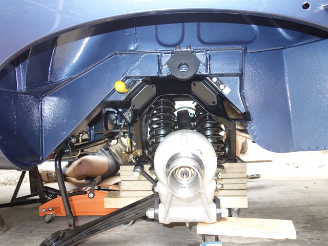
As they are attached at an angle of 45 degrees, this would need each rubber mount to compress by √2 x 3mm to obtain hole alignment. So they became the prime suspect in the fitting problems.

A few tests of a mount in a vice suggested that it might be possible to achieve the necessary compression in the rubber section but exactly how was still to be determined. So the decision was made to continue rather than abandon the installation weekend.

The front of the chassis was raised in relation to the rear in an attempt to use the weight of the car to compress the rubber in the rear mounts. It still wasn’t sufficient – we needed more weight in the rear. A few moments later, Martin and I were standing in the boot while John assessed whether this had achieved anything other than a comical moment.

Eventually each bolt was persuaded one by one until the IRS had been fitted. A successful method was to insert a screwdriver into the second bolt hole to lever the first bolt hole into alignment and then tap the bolt home. I later found out that such fitting issues were far from uncommon.

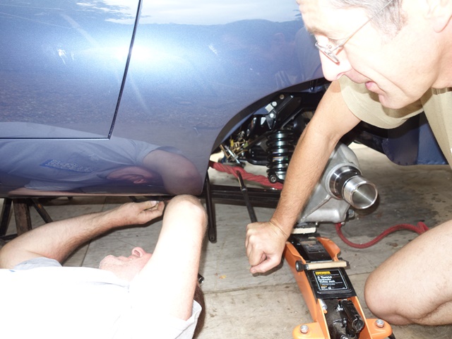
We just needed to connect the radius arms to complete the job. Unsurprisingly they were also a country mile off fitting on to the cups on the chassis and were also twisted in relation to the cups because there was no load on the suspension. The solution was a three man job. John applied a tourniquet to draw the IRS cage forward so the radius arm and cup aligned. At the same time I rotated a G-clamp attached to the radius arm while Martin fitted the retaining bolt.

Just the radius arms to go Applying a tourniquet to pull into alignment G-clamp was also needed

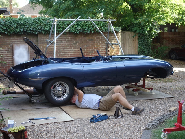
Almost the entire day had been taken up with fitting the rear suspension but at least we had the satisfaction of finally lowering the car onto two of its new 5″ wheels. I had been wildly optimistic on what could be done in a day but nevertheless was pleased with what had been achieved.


The front suspension and engine would have to wait for another day ….

Aug 212013
 

This is more of a retrospective post as the IRS rebuild was originally completed in line with the indicative chassis completion date of May 2011 given by Hutsons. I had stripped and painted all the components but needed a specialist to address the differential. By chance I decided to get it done by Alan Slawson from AJS Engineering.

I wasn’t aware at the time but one the two Jaguar World books that persuaded me to buy the E-Type included a section covering the IRS rebuild. Alan was the person they entrusted to do their rebuild so it seemed fitting he would also be doing mine.

When I arranged to pick up the diff I asked him if he would be prepared to do the full IRS rebuild. Although he was semi-retired he agreed, as long as I wasn’t in a rush for it. The aim was to free me up to tackle the 101 other things needed to be ready for the return of the chassis.

In the end Hutsons took much longer than hoped due to a very healthy backlog of restorations. It was shame really as I’d have preferred to rebuild it myself and would have had ample time to do so. Several months after dropping the parts off, Alan had completed the IRS and even drove over from Essex to drop it off. At his suggestion Gaz adjustable shock absorbers were fitted in preference to the Koni Classic ones I’d supplied.

Also at his recommendation was to rotate the larger radius arm bush through 90 degrees. The rubber section has two elongated holes which are normally orientated so they are front and rear. Rotating the bushes so the holes are at the sides marginally increases the fore and aft stiffness, which is in the direction of forces through the radius arm. I subsequently found out that this is common practice.

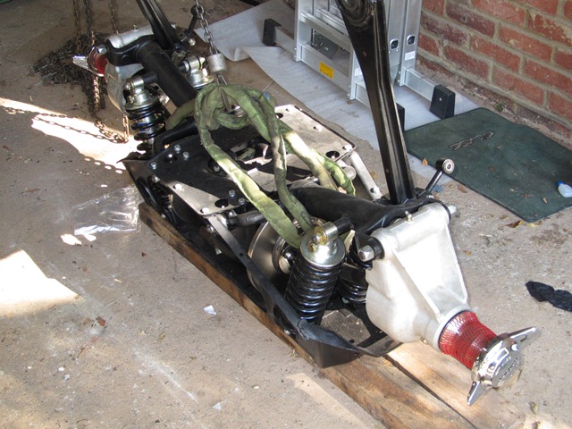
The IRS unit is quite a heavy unit so I knocked together an amply sized trolley using two sheets of 22mm chipboard. Great for moving it around but the down side of its generous proportions was that it bent significantly under the weight.

Building up the front suspension

 Front Suspension  Comments Off on Building up the front suspension
Aug 152013
 

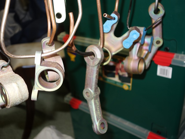
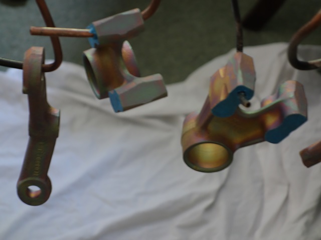
The plating didn’t go quite to plan as I hadn’t expected (or asked!) for the parts to be yellow passivated so the final look wasn’t really what I had in mind. The photos below show the ‘oil slick’ appearance that comes from the yellow passivation. Another lesson learnt – don’t assume anything and be explicit in your requirements!

I’m sure they used it with best intentions, as it provides slightly greater protection, or it’s the default colour but I’m kicking myself now. Still a number of people have advised on painting rather than plating for a more durable finish – now I’ll have the best of both worlds!! Anyway the aim is to drive the car rather than polish it for show!

The bracket faces that are in contact with the engine frames and the fulcrum shafts were masked to avoid any clearance problems later on. All the suspension parts were then given three coats of aluminium Epoxy Mastic 121. The parts were left for a couple of days to allow the paint to fully cure and harden.

It was also time to come off the fence as I needed to decide on whether to use the standard rubber bushes or install ‘upgraded’ polyurethane ones, such as Superflex. I’d fitted polyurethane bushes on my Elise but after several years the bushes would squeak going over even the slightest road imperfection. I think this was probably largely due to the garage not applying the correct grease (if any!) when they were installed.

In the end I’ve decided to keep to the standard rubber bushes, which were fairly easy to press in the bushes using a vice and liberal amounts of washing up liquid.

Standard rubber bushes were used in the end rebuilt wishbones and uprights ready to go on Sealed for life XJ40 lower ball joints were used

I’d been toying with the idea of buying a hydraulic press since the start of the restoration but, each time I’d needed one during the rebuild, the job was farmed out. I couldn’t justify the cost of a press now, at such a late stage, and so took the front uprights, hubs and a print out of the suspension section of the manual to the local garage while I built up the wishbones.

I hadn’t felt the need to state the obvious, that the hubs have different handed threads, because they were clearly labelled ‘LH’ and ‘RH’. Sure enough, when I picked them up a couple of days later, they had put the hubs on the wrong way round! What was that about not assuming anything and being explicit in my requirements!

I thought it would be easier to sort that out once they’re on the car and set about finishing off the simple task of putting the upper and lower wishbones together.

Finally the sealed for life XJ40 lower ball joint units were fitted to the uprights. Far easier than the original set up which required shimming. The suspension parts are now all ready to be bolted on next weekend.

The plan was to install both the front and rear suspension, steering, the engine and gearbox and all the engine bay components with the aim to get the engine running. Unfortunately I’ve not managed to sort out the dreaded fuel tank yet so the testing of the engine will have to wait.

Aug 122013
 

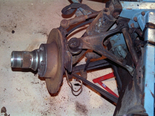
The dismantling of the front suspension was by far and away the hardest part of the stripping down. I suspect it had never been apart since it left the factory and hadn’t seen much in the way of maintenance.

The only parts that could be removed were the two upper wishbones. It took some fairly heavy blows with two club hammers to get the ball joints to split it. The rest of the suspension had to be taken off the car in one piece so it could be soaked in penetrating oil for many weeks.

Front suspension had seen little maintenance Dismantling was easiest off the car Axle carrier limited access to the lower ball joint

Even after that time, it hadn’t made the slightest bit of difference and all the bushes and bolts were still refusing to come off. I tried to press out one of the shock absorber bolts that also hold the two wishbone arms together. However all I succeeded in doing was to bend the bolt!

Progress was painfully slow and often I would get to a part that wouldn’t budge no matter what I tried. So I’d put it to one side and come back to it in a week or so, with renewed vigour. Eventually, over three months later after applying everything from penetrating oil, heat, cold, fire and a lot of frustration, it had been dismantled into the individual components.

Upper ball joint is prone to wear Lower ball joints will be replaced with sealed for life ones Suspension parts ready for shot blasting

The plan was to get the upper wishbones machined to accept a modern ball joint and then shot blast the parts before re-plating them. The lower ball joints will also be replaced with more modern XJ40 sealed for life units. Nowadays most people seem to Nickel plate the suspension as the original Cadmium is no longer available. It’s generally limited to aviation components now due to the toxicity of the plating process.

I’m not a great fan of Nickel plating as I’d had my Elise suspension plated a few years ago and it hadn’t lasted very long. The main problem is that it isn’t a sacrificial coating like Cadmium and Zinc. Once the surface is damaged it corrodes from beneath. It’s also quite difficult to get rid of when it will inevitably need redoing and requires special Nickel stripping.

After a lot of research I found the best alternative to Cadmium was Zinc-Nickel. It also has the benefit of having a duller finish and so is a lot less blingy that bright Zinc.

Several others recommended just painting or powder coating, although this is somewhat frowned upon by the purists. Also a more flexible paint coating can hide stress fractures until it’s too late! I’d played around with spraying some of the zinc plated bracketry with a satin lacquer which produced the best compromise. It provided a ‘toned down’ plated look but with the added benefit of more durability. Decision made!

Not many companies do Zinc-Nickel plating and generally don’t take private work from individuals. Fortunately I was able to arrange for my parts to be Zinc-Nickel plated as a favour. However, without asking for it, they had yellow passivated them so they had an ‘oil slick’ appearance which I think would have looked awful on the car.

So to plan B – rather than adding a satin clear coat as planned, I would paint them in aluminium Epoxy Mastic 121. The combination of the plating and Epoxy paint should mean they keep their appearance for many years to come.

Prop Shaft Refurb

 Transmission  Comments Off on Prop Shaft Refurb
Aug 122013
 

As the prop shaft’s spline joint is sealed for life, the refurbishment of the prop shaft is limited to replacing the UJs and tarting it up with a lick of paint. A member of the forum has suggested Epoxy Mastic 121 for a tough rust-resistant paint that is applied to bare metal and as an alternative to POR15. So I purchased both black for the various brackets etc and aluminium for the backs of the bumpers.

The prop shaft and yokes were then wire brushed back to bare metal and then given several coats of black Epoxy Mastic. It’s a lot easier to work with that POR15 although the finish isn’t as smooth, having a noticeable orange peel effect. Oddly the aluminium paint did provide a smooth finish.

Everything was going smoothly until the final UJ when I allowed one of the roller bearings to fall into its cup. Fortunately it was fairly easy to press out and start again. To seat the new UJs the prop shaft was mounted onto the rear axle and the prop shaft given a sturdy tap with a wooden mallet in each of the four directions of the UJ. The aim was to push the UJ cups hard against the retaining circlips and loosen the stiffness in the joints.

 Posted by at 6:41 am