While researching the best piping to use for the hydraulics, I’d found out that copper piping is banned in many countries as it is susceptible to work hardening over time. I thought it wise to switch to Cunifer pipes as it is a safety issue, even though I had already purchased a copper pipe kit from Automec.
In the end I took the cautious approach to all the braking system and planned to have the master cylinder and servo units professionally renovated. The main reason being an inspection of the master cylinder had revealed some pitting and I wasn’t confident it would be possible to get a good seal without it being re-sleeved.
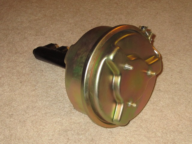
Also the fixing studs on the servo unit were all at odd angles so something was amiss. Opening up the servo uncovered a bodged weld ‘repair’ to one of the studs. The servo casing looked as if it had been fractured around the stud and so would need replacing. The units were sent off to J & L Spares to be repaired. However the cost of repairing the master cylinder was more than the cost of a new one so I opted for the latter.
| Servo Mounting Studs |
Bodged repair weld |
Renovated Servo |
|

|

|
|
Apart from a basic understanding, I’d never really paid much attention to the detailed workings of servo assisted brake systems. So it was out with the Jaguar service manuals to get a better understanding of how the vacuum boost is controlled. It should help if troubleshooting is required later on, especially as I will be tapping into the vacuum circuit for the EDIS Megajolt control module.
It’s actually quite simple. A reservoir tank stores a ‘vacuum’ by being connected to the inlet manifold, which is at a lower pressure than the ambient air pressure. This is then used to boost the braking force when the brake pedal is pressed.
 The servo unit contains to volume chambers which are both connected to the vacuum reservoir but separated by a diaphragm. The servo hydraulic piston is operated by fluid forced from the master cylinder but also by a spindle attached to the centre of the diaphragm.
At rest when no braking force is applied, there is no flow of hydraulic fluid and both chambers are at equal pressure and so no force is exerted on the piston.
 However when the brake is applied, the master cylinder piston is pushed down the bore forcing fluid from the master cylinder to the servo unit. This operates the servo hydraulic plunger. Near the end of the travel of the master cylinder piston, it operates a reaction valve.
The reaction valve first disconnects the servo’s rear chamber from the vacuum supply and then opens the rear chamber to atmospheric pressure. This creates a pressure difference between the front and rear chambers, which forces the diaphragm and attached spindle forward. Thus increasing the force applied to the servo hydraulic piston.
Once these were installed on the car, it was time for the fabrication of the hydraulic piping ….
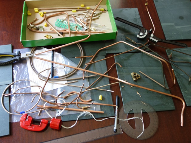
The brass fittings were salvaged from the Automec kit and the copper piping used for making mock-ups of the more complex sections. Cunifer piping is typically sold in 25 foot coils which was more than enough. So I had plenty spare ‘just in case’ I made a hash of making the individual pipes.
I now needed to straighten the replacement Cunifer piping and also to obtain a brake flaring tool. Initially I purchased a flarer from Machine Mart which was little short of useless and had the typical Made in China quality about it. I ought to know better by now!
There’s always a number of old, quality flaring tools on eBay but these usually change hands for well in excess of £100. I think people just resell them back on eBay once they’ve finished their restorations, which is what I planned to do. However after being outbid on numerous times I gave up as I needed to press on.
 After a recommendation, I picked up a new Oakes tool from Automec at the Jaguar Spares Day for a show price of £90. Quite a bit for a tool for a one off job but it does produce good, consistent flares every time. All in all, a good investment and a quality tool.
I’d previously straightened all the copper piping over a form (covered in a previous post) but subsequently disposed of the wooden form, thinking I’d no longer need it!
I did come across a straightening tool produced by a company called Kwix UK which seemed promising. However it only straightens a pipe of a fixed diameter so I’d need three tools for each of the pipe diameters used for the brake and fuel lines.
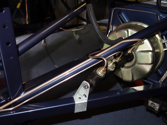
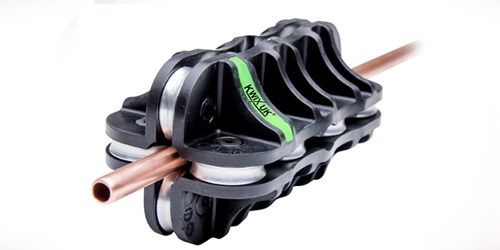 The 1/4″ brake pipes linking the master cylinder and servo run around the engine frames. I thought any slight bends/kinks in these pipes would be more noticeable as they run along the straight edges of the frames. The 1/4″ tool was purchased as a trial and it worked well so I got the 5/16″ one for the fuel lines.
Unfortunately this time, the pipe passed straight through without a hint of straightening and emails to the company received no response. I think they probably just sent the wrong sized tool but couldn’t be bothered with addressing customers’ issues so I won’t be dealing with them again!
The difficulty with bending the pipes was that often it wasn’t possible to trial fit the pipe after each bend was made. The unbent length would usually foul some part of the bodywork, stopping the pipe being placed in situ to mark the exact point for the next bend.
There was little margin for error for pipes that had to be bent in different planes. It only takes slight errors in the position of the bend, the angle of the bend or the plane in which the bend is made for it not to fit and the errors are magnified once another bend or two is added.
 The mantra measure twice cut once applied here as, once bent, it’s almost impossible to re-straighten a pipe, especially the larger diameter piping. In fact it was more like measure 10 times, bend once! I probably had to discard just under half of my first attempts.
Having completed the hydraulics, I’m not convinced of the wisdom of purchasing kits as it would be nigh on impossible to get all the pipes right first time. So I’m glad I decided to fabricate my own pipes and it was quite therapeutic.
Having said that, I still managed a few numpty moments. A couple of times I allowed the brass fitting to slide away from the flared end onto the wrong side of where the bend was then made. Another scrapped length of piping!
The copper kit didn’t go completely to waste as it was cut down into shorter lengths and used to get correct position, angle and plane for a small section with say 2 or 3 bends. This could then be offered up without fouling the bodywork before making the same bends in the full length of pipe.
I had all but a few of the original pipes to use as templates however I did deviate in a couple of areas:
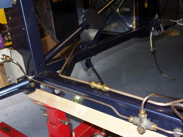
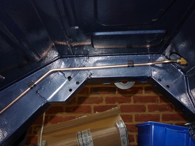
- The pipe to the rear runs along the under floor box section but divert so it is clear of the mounting bolts for the torsion bar reaction plate. In doing so I think the pipe would be more exposed to damage. I continued running along the box section and will just need to take care when doing up the torsion plate bolts.
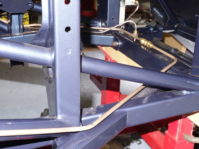
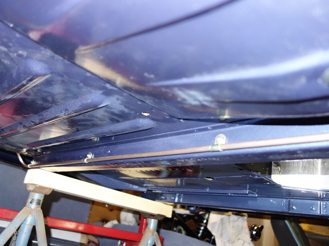
- I thought it looked neater having straight piping around the front of the engine frames rather than trying to get them to mirror all the rises and falls in the frame profile. Therefore, just before the front brake union, the smaller front brake pipe jumps over the larger pipe rather than underneath.
Also my pipe bender couldn’t get as tight ‘U’ bends from the brake and clutch master cylinders and other methods were prone to causing the pipe to start collapsing.
Hydraulic Pipe Routing
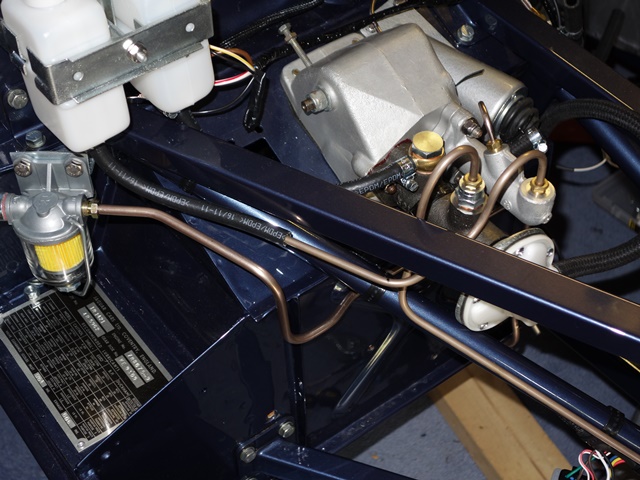
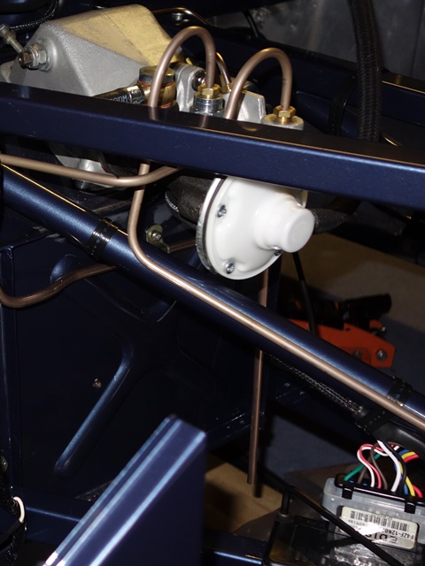
Below are a few photos of the trial fitting of the various hydraulic pipes on the S2.
| Clutch from Master Cylinder |
Clutch low pressure pipe |
|

|
|
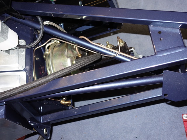
| Brake – Master to Servo |
Brake – around Picture Frame |
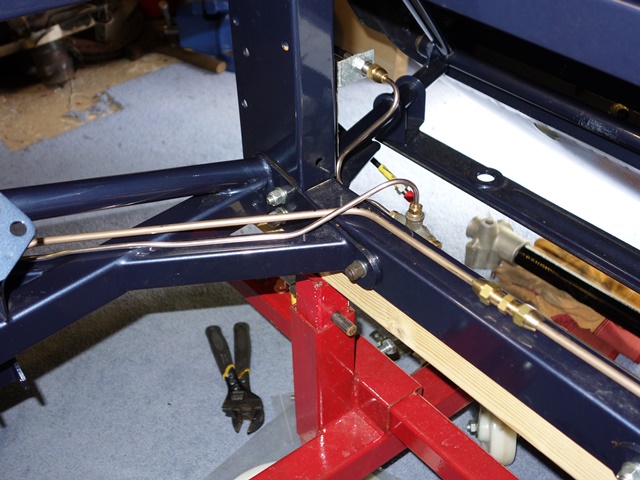
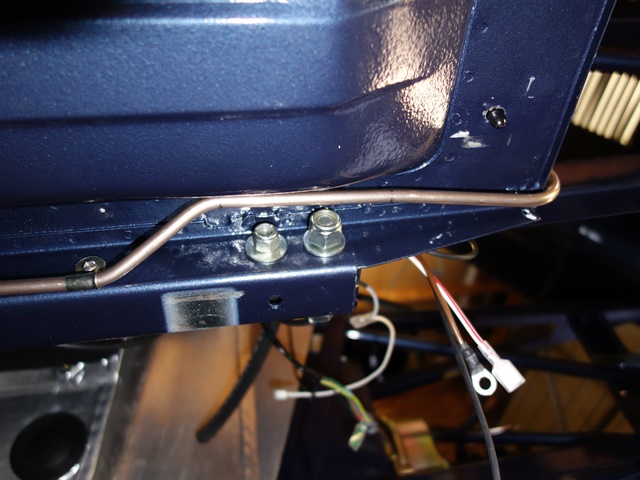
Brake – Master to Servo & To Front |
|
|
|
|
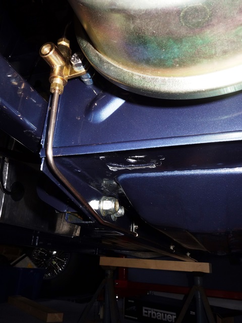
| Front feed over Master to Servo |
Left Front Brake |
Righr Front Brake |
|
|

|
|
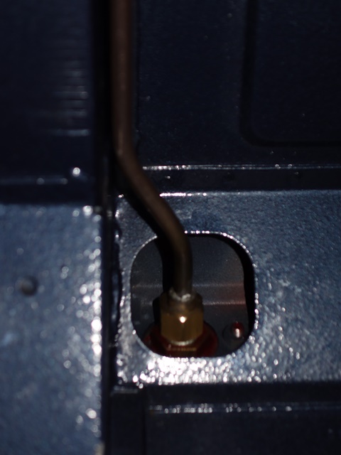
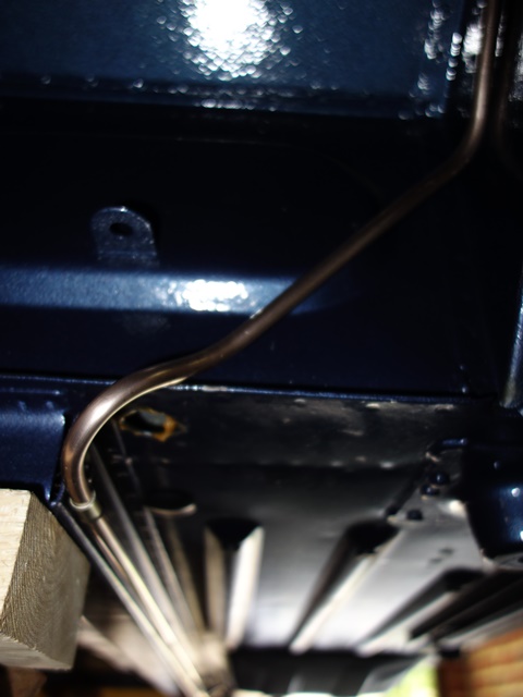
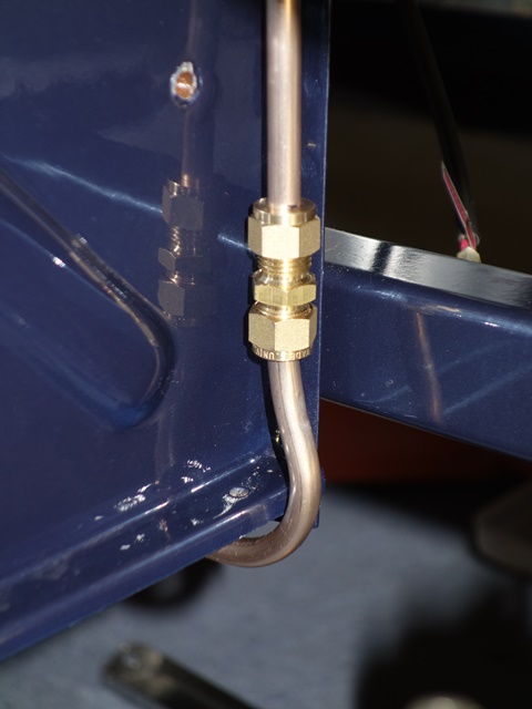
| Servo to Rear Union |
Union to Rear |
A few off cuts!! |
|
|
|
|

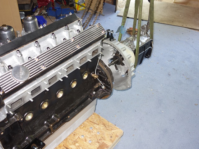
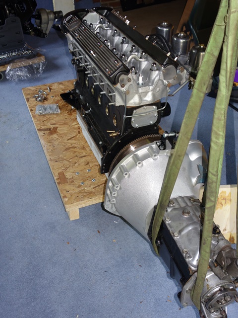
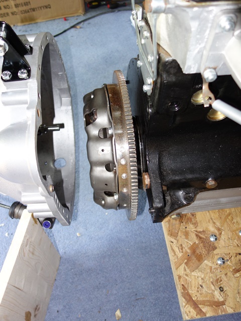
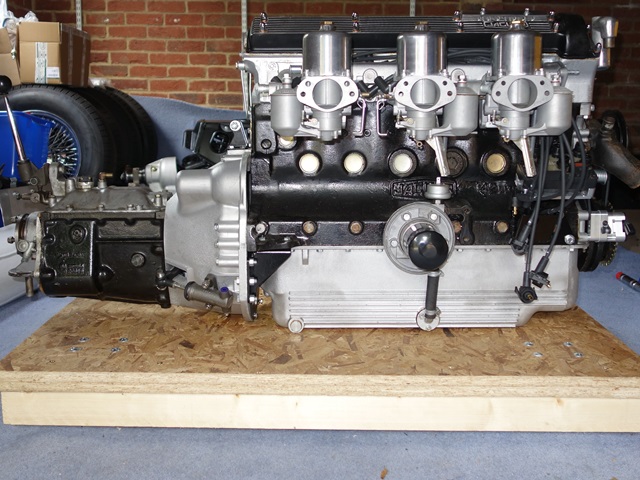
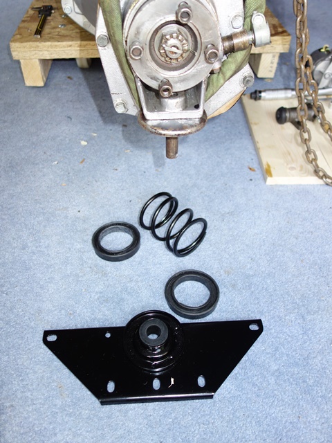
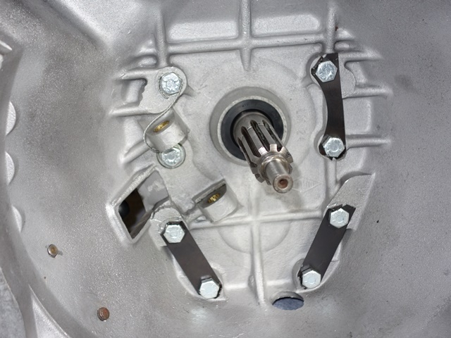 The bellhousing had already been ultrasonically cleaned and just needed the rear oil seal inserted before being bolted to the gearbox. Three lock tabs are used to prevent six of the bolts from working loose. The remaining two bolts, next to the clutch fork, use safety wire instead.


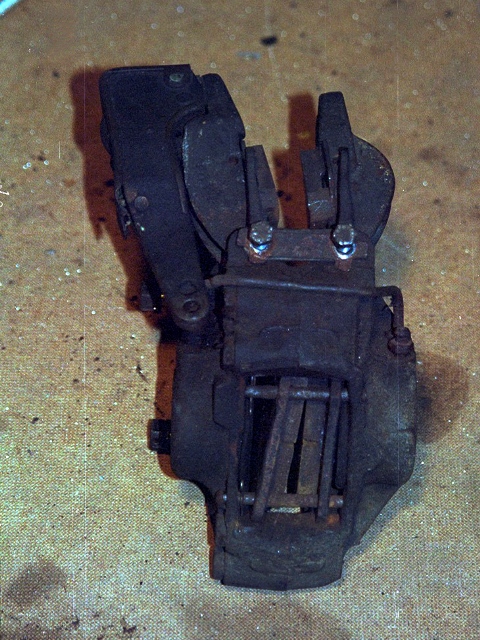
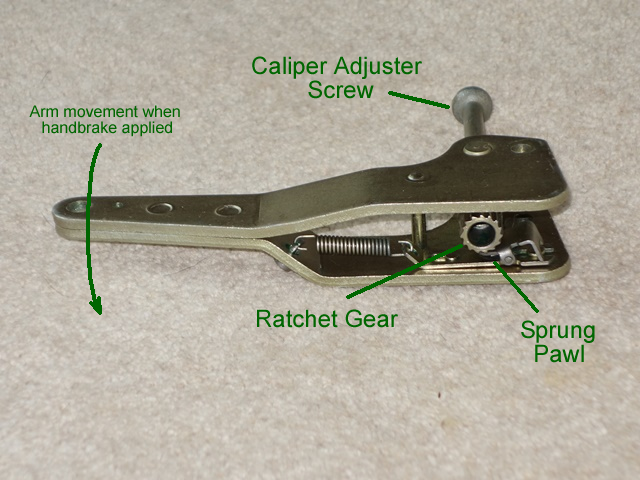 The handbrake system is self-adjusting using ratchet mechanisms to automatically compensate for the pad wear. The distance between the pad faces is determined by how far the caliper adjusting screw has been screwed into the ratchet gear.
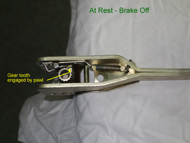
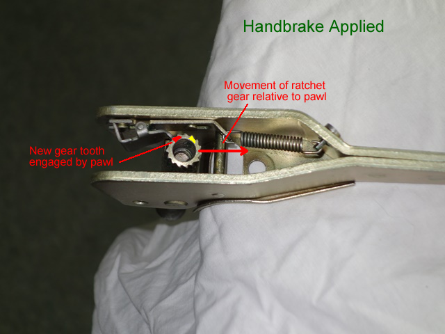
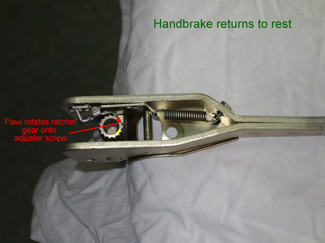
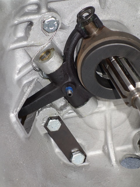
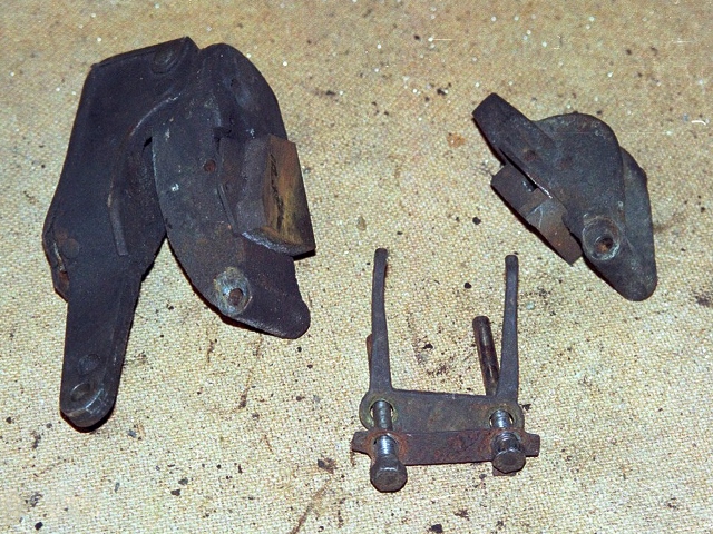
 I’m not sure if there is a correct or recommended order for rebuilding the handbrake mechanism. I started with the internal parts of the operating arm; the pawl slots onto protrusions on the arm which guide and limit its travel. A tensioning spring attaches to the pawl and the other end to an anchor pin pushed through the operating arm.
 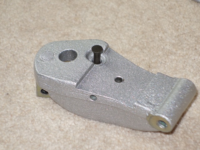 The operating arm could then be attached to the outer caliper arm. I found it easier to fit the operating arm return spring first which is attached at one end to an anchor pin pushed through the caliper arm and the other to a shaft in the operating arm.
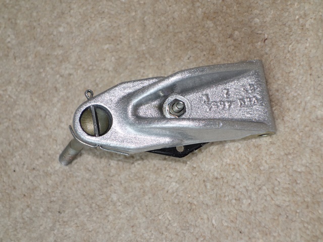

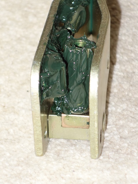
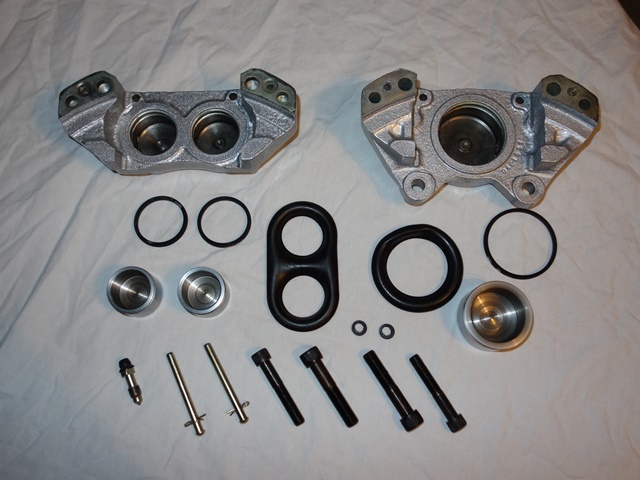 Caliper rebuild kits are readily available from many of the usual suppliers and contain the square sectioned seals which sit in recesses in the caliper piston bores and the outer dust shields.
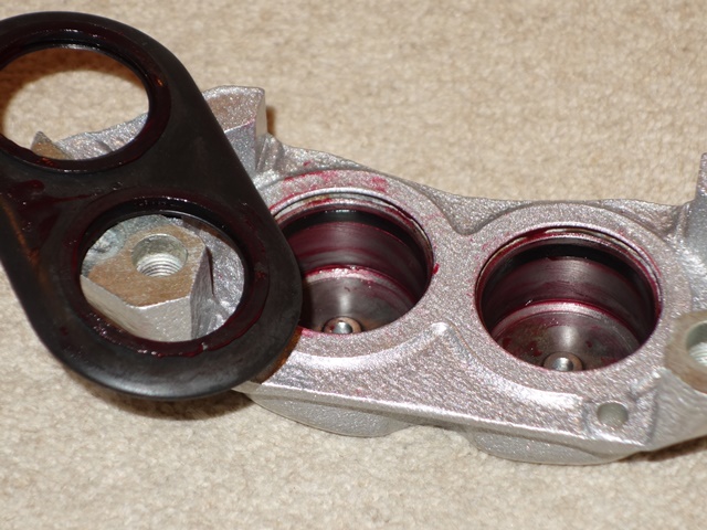
  The photo to the left shows the passageways for the brake fluid from the face where the two caliper halves join (the tip of the screwdriver is just about visible at the top of the upper piston bore). A corresponding passageway exists from the face of the other caliper joint and a small channel links the two piston bores. Thus providing the free flow of fluid between all the pistons in both halves of the caliper.
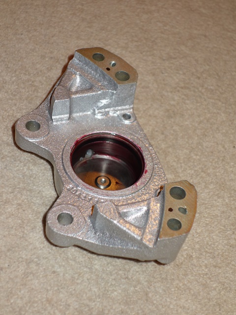


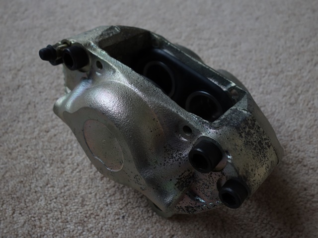

 The easiest method of extracting the pistons was to insert a bleed nipple into the hydraulic feed and use a foot pump to force the pistons out.
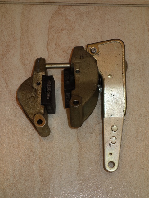


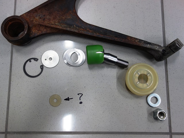 In my hour of need I turned to E-Type International Rescue – McLaren’s Skunk Work team. There was some bemusement as to why the kit contained a pack of 9 shims rather than machining the wishbones correctly.
  The ball joint bores were profile milled with a ball-ended tool around the circumference, progressively stepping down after each revolution until it had cut to the required parallel depth.
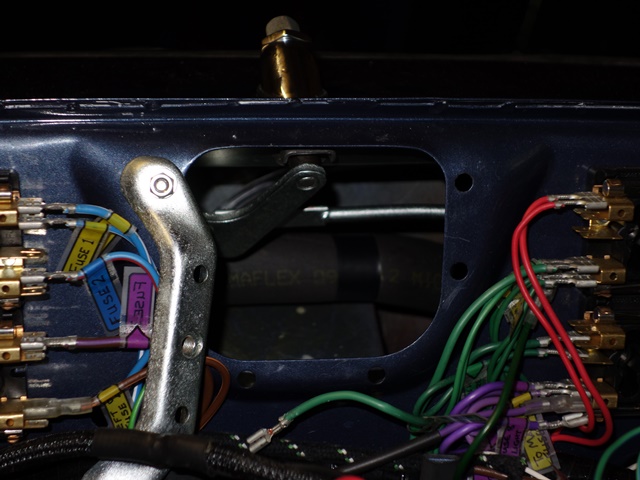 The final item to install within the bulkhead was the wiper rack, which really ought to be very straight forward. However the thickness of the heater pipe insulation I’d used caused problems again. The reduced clearance stopped the entire rack to be fed into the bulkhead as one unit.
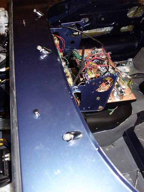
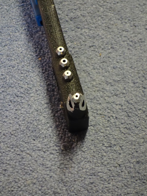
 There’s little worth noting regarding the fitting of the windscreen washer and jets. Fortunately the chromed jets were the first thing I’d decided to install before the bulkhead pipes and wiper rack, which made it possible to fish out dropped washers and wing nuts.
  I’d lost count of the number of times I’d dropped either the washer, the nut or both. Finally common sense prevailed.


 All seemed sensible advice so I purchased some dense foam, pipe insulation. The other issue I’d already found was that the shoulder of the rivet gun was too wide to get the mussel onto the rivet head.
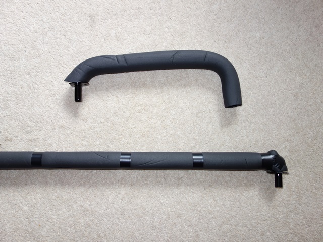 I ended up cursing the fact that I’d insulated the lower heater pipe. At least I probably should have used much thinner lagging. It made the fitting of the lower vacuum pipe so much harder and later the routing of the windscreen washer tubing.
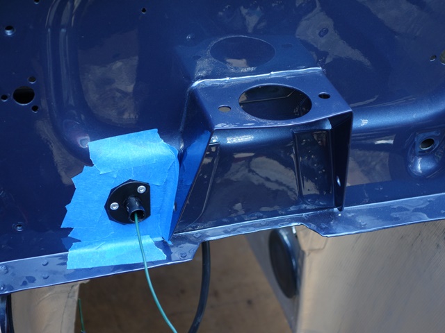 I’m also glad I taped the surrounding area as the head of the rivet gun tends to jump off the rivet when the pin snaps. I’m sure I’d have had several chips without it. In fact the only touching up needed was to one of the flanges but this was more to do with the adhesion of the Hammerite to the zinc plating.