The hardest part of the process was actually the removal the fuel pump! It’s located in the boot space above the offside wheel arch. The pump is attached to the body via three rubber mountings to an L-shaped bracket bolted to the pump body and a circular bracket clamped around the pump’s coil housing.
Each rubber mounting is comprised of two threaded studs joined by a rubber section, which reduces the transmission of vibrations to the chassis when the pump is running. The problem was that, even with a period of soaking with penetrating oil, any rotation of a nut would simply be taken up by the rubber section deforming and not undoing the nut from the stud. Finally, after much cursing, I gave up and resorted to a bolt splitter.
 Once removed from the car, the dismantling of the pump is a fairly straight forward process. I started by removing the six screws around the base of the coil housing which allowed the pump body and coil housing to be separated, revealing the diaphragm and pumping chamber.
The inlet and outlet value assemblies are retained under a clamping plate secured by two screws, as shown in the photo. Once the clamping plate was withdrawn, the valve assemblies, inlet gauze filter and gaskets could be removed. The valves had to be prized out which resulted in their destruction however they were to be replaced as a matter of course.
 The dismantling of the pump body section was completed by removing the inlet and delivery chamber covers. The inlet cover is simply a cork gasket and cover retained by a central bolt and washer. As far as I can tell the inlet chamber smooths the flow of fuel by having an air pocket which can expand or contract according to the pressure in the chamber. Four screws retain the delivery chamber cover under which is an ‘O’ ring, diaphragm and plastic gasket, see photo. Again the chamber provides smoothing of the flow of fuel due to the flexing of the diaphragm.
 The disassembly of the coil housing section was also a simple process. The black plastic end cover was withdrawn once the terminal nut had been undone and the tape sealing the end cover/coil housing join removed. Underneath the cover is the contact point assembly, which consists of a Bakelite pedestal holding the sprung upper contact points and a rocker mechanism holding the lower contact points. A small capacitor is connected between the upper and lower contacts to suppress arching across the points gap as arching causes premature deterioration of the contact points.
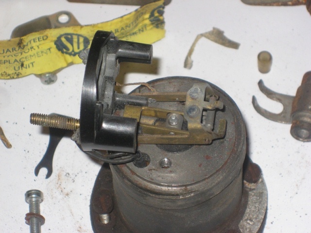 After the two screws had been removed the pedestal could be rotated away from the rocker mechanism. Both the upper and lower contact points were badly corroded. Finally the rocker mechanism and armature & spindle were removed. This can be achieved by disconnecting the leads to the rocker mechanism and then rotating it until free from the spindle. Alternatively the armature/diaphragm can be rotated anticlockwise until the spindle is free of the rocker mechanism.
 When the pump was first removed what appears to be a capacitor (see the photo on the left) was connected across the positive terminal and earth. This part doesn’t appear on the Jaguar parts list so I assume this must have been added at a later stage. As previously mentioned capacitors were used to suppress electrical arching but I’m not sure whether this capacitor was added for this reason or possibly to suppress electrical interference produced when the pump is in operation.