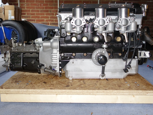
Progress has been slow of late and the finishing line still feels some way off. I’m still waiting for the trimmers to have a slot to fit the hood and some of the outstanding internal trim. At least the enforced delay would allow some teething problems to be addressed. The most pressing being issues with clearance of the gear lever and gear selection.

Removing gear lever gaiter
revealed lack of clearance
with the gearbox cover
Something was seriously amiss with the positioning of the gear lever in relation to the central console. The lever was too far back making it difficult selecting either 2nd or 4th. Even once selected, the convoluted rubber gaiter was being compressed against the console, resulting in a tendency to pop out of gear into neutral.
The console couldn’t be moved rearward as it was already in contact with the rear bulkhead. Likewise there’s no adjustment in the positioning of the lever so it couldn’t be moved forward. The only option would be to undo the engine mounts and stabiliser to prise the whole transmission forward, but this would only gain a millimetre or two at best.
I’d been forced to remove the centre console in order to drive the car, which allowed me to swap over the rubber gaiter to one used on the later v12 models. The bulbous, convoluted design had been changed to be more slim-line. Several members of the E-Type forum had suggested using the later design to alleviate minor clearance issues with the centre console. Although I wouldn’t consider the lever impacting the metal gearbox cover as minor!
 |
 |
 |
Convoluted S2 gaiter versus
slim-line V12 gaiter |
The gaiter is secured to the
gearbox cover by a clamping ring |
V12 gaiter is more suited
to the shape of the console |
At this point I just happened to notice the mounting of the gear lever mechanism differed from the diagram in the parts catalogue. The company chosen to recondition the gearbox had missed out some fibrous Tufnol washers and mounted the main spring washer on the wrong side of the gearbox lid!
Repositioning the spring washer to its intended location gained around 8mm of clearance and, with the addition of the Tufnol washers, removed all the free play in the gear lever action. Much better! It should be sufficient to stop popping out of 2nd & 4th once the central console is refitted.
 |
 |
 |
Parts manual shows correct
location of spring washer |
Incorrect location
between jaw and lid |
Lever mechanism components
(now including missing washers!) |
Although the clearance problem was just masking a potentially more serious issue. More often than not, changing down into 2nd gear would result in awful graunching. It was fine double de-clutching so I suspected there might be an issue with the synchromesh. I was trying to kid myself that the reconditioned gearbox just need ‘bedding in’ simply because I just couldn’t contemplate having to fix an internal gearbox issue!

Synchromesh relies on friction
between the two cone surfaces
However, from my limited knowledge of gearboxes, it uses standard interference fit synchromeshes which helps engagement by matching the speed of the chosen gear to that of the output shaft.
Therefore a gearbox with a new synchromesh would have ample friction. Graunching would point to a lack of friction and the need to replace the synchromeshes.
It was time for a second opinion so again I turned to John and Martin who’d installed the IRS many moons ago. Their advice was to perform some investigative tests; first to rule out the clutch disengagement, which might result in similar symptoms, and the second to check the action of each synchromesh to confirm which, if any, were the route of the problem.
I hadn’t considered the clutch but if it wasn’t disengaging properly, the layshaft and gears would still be driven by the engine and the synchro would be acting as the clutch. Therefore likely to produce graunching, although I guess in all gears.
The suggested test to rule out a disengagement issue was to depress the clutch, with the hand and foot brakes off. Wait for around 10 seconds to allow the layshaft and gears to stop spinning and then select a gear. If the clutch wasn’t fully disengaging, the gears would still be spinning and the car would show signs of wanting to pull away.
On the positive side, the outcome was that the clutch was operating correctly. Although it was therefore pointing more to a dreaded synchromesh problem. Their next tests were of a similar nature, depressing the clutch from neutral. However rather than waiting to allow the gears to stop spinning, the gear lever was pushed immediately and firmly into the chosen gear without any wait. This would be done for each gear, selecting with both a fast and delayed lever push.
The theory being that a worn synchro would not develop sufficient friction with the selected gear to enable their speeds to be matched before their dog teeth engaged. The faster the action the less time there would be to synchronise the speeds.
The test should be repeated several times for each gear, doing a full ‘re-set’ each time (from neutral and clutch up), to see if a pattern emerged. If the synchros were working correctly there wouldn’t graunching on either the fast or delayed action. A suspect synchro, in my case 2nd, would graunch in the ‘no-delay’ fast instances and possibly on the delayed selection.

A run in the car without the cover
revealed the cause of the problem
(note – relocated spring washer)
I was very relieved that no graunching was evident in any gear, for either action. Perhaps it wasn’t an internal gearbox problem after all, which would require an engine out fix. I took the opportunity to take the car for a spin, while the gearbox cover was off, so I could see the selection mechanism at work in more realistic road conditions.
What I observed surprised me and explained the graunching that I’d been misdiagnosing as a synchromesh problem. The corrections in the lever mechanism had made subtle changes to the geometry by moving the lever directly over the quite narrow 1st/2nd selection rod. Previously it had been at a slight angle so the lever could also catch the reverse selection rod at the same time.
More importantly the reason for the graunching was actually caused by selecting reverse gear instead of 2nd!! A sprung plunger is used to avoid accidentally selecting reverse while using the forward gears. However the resistance it offered was so weak it was quite easy to go beyond 2nd all the way into reverse without realising.
 |
 |
Gearbox lid removed to check
selector rod operation |
Selector arrangement and
reverse plunger & adjustment |
A sprung ball bearing presses into a groove in the plunger to create the resistance and can be adjusted via a setscrew. Even so, for a given setting, there was a noticeable difference in the effort required to depress the plunger depending on whether the lever was starting in the 1st/2nd or 3rd/4rd planes in the gate. This was simply due to momentum, with less effort required from the 3rd/4th side of the gate.
I opted to set the desired resistance from this position which should minimise the frequency of accidentally selecting reverse while changing down from 3rd to 2nd. The compromise is that it needs a good shove to select reverse when the lever is in the 1st/2nd plane, but this would typically be while stationary.
It was a great relief to get to the bottom of the gearbox problems although the only slight niggle is occasionally not being able to engage 3rd from 2nd. The 1st/2nd selection rod doesn’t always quite reach its neutral position but allows the lever to cross the gate for 3rd. As it hasn’t reached neutral, the interlock is doing its job and prevents another gear being engaged, in this case 3rd.
If baulking occurs going from 2nd to 3rd, the lever must be returned to the 1st/2nd plane to ensure its knocked into neutral before going for 3rd again. I took the top of the gearbox off to see if the ‘O’ rings were causing too much resistance in the movement of the 1st/2nd selection rod for the detent to pull/hold it in neutral. But all seemed in order.
It appears that this is not uncommon and can be avoided by a more sympathetic gear changing technique using light finger pressure and ‘palming’ the lever to guide it. I had been changing from 2nd to 3rd by applying a constant forward and sideways force rather than three distinct movements.
The double de-clutching I had used to overcome the graunching, adding weight to my synchromesh diagnosis, had worked simply because it changed my technique of changing gears. Therefore avoiding accidentally selecting reverse.
Fingers crossed this will be the end of the gearbox issues!!


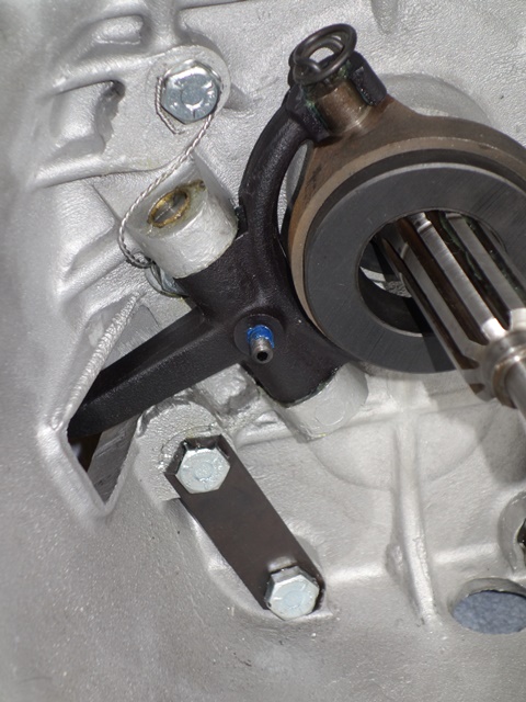
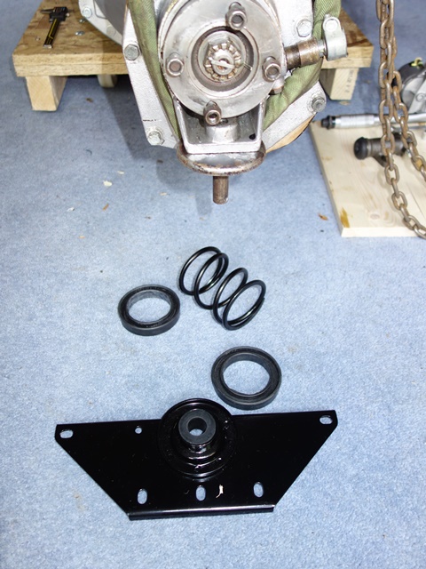
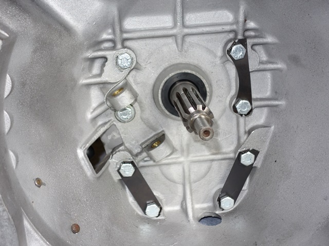 The bellhousing had already been ultrasonically cleaned and just needed the rear oil seal inserted before being bolted to the gearbox. Three lock tabs are used to prevent six of the bolts from working loose. The remaining two bolts, next to the clutch fork, use safety wire instead.