Apr 192015
 

Static safety belts had originally been fitted to my car. However I’ve never really got on with static belts the few times I’ve driven cars fitted with them. The main issue is at junctions, when it’s often helpful to be able to lean forward slightly. Something that would be even more desirable with such a long bonnet.


Inertia belts were an optional extra
(Image courtesy of E-Type forum)

I had therefore decided to ‘upgrade’ to more modern inertia belts for practicality reasons. Having made the decision, the next dilemma is how to mount them. They can be fitted to brackets mounted on the rear bulkhead (as Jaguar did as an optional extra).

The other alternative is to mount them to the rear bulkhead inside the boot space. The downside with the boot mounted belts is slots for the belts would have to be cut into the bulkhead.

I think mounting large inertia reels behind the seats spoils the look of the interior. So a boot mounted kit was ordered from Quickfit Safety Belt Services. I had toyed with either blue or red webbing. In the end, deciding to keep them inline with interior colour scheme. Although their range of reds is rather limited: a burgundy or vibrant red. The burgundy looked too dark so I opted for the red …. and sunglasses!


Quickfit’s seat belt kit

Quickfit were very helpful, guiding you through the various options. They also warned me that they make their belts for classic cars in batches, once sufficient orders have been received, so the order may take between two weeks to two months to fulfil. Supplier delays for some of chrome fittings pushed this out to three months before they finally turned up!

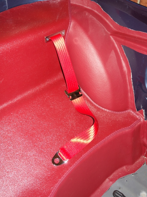
The inertia mechanism is designed for the belt to be pulled out from the reel at a specific angle (or range of angles). For the boot mounted installation, this is at 90 degrees to the reel’s mounting plate which must also be mounted vertically. At any other angle the locking mechanism stops the belt, so the same reel could not be used for mounting inside the cabin.

The seat was fitted in order to get the correct mounting position, with a length of webbing held horizontally against the shoulder back to the bulkhead. Ideally the belt should approach the wearer’s shoulder horizontally or slightly downwards. The problem is the rear bulkhead on the OTS E-Types isn’t particularly high, so the placement of the reels is compromised to a certain extent.

They were mounted as high as possible so, for me, the driver’s belt is horizontal in my normal driving position, with the seat back partially reclined. If the reels were fitted low down at the base of the bulkhead, the forward force due to an impact would be redirected downwards through the wearer’s shoulder. Not ideal!

Locating the best mounting position Marking out the areas to drill/cut

I’d made a card template so the mounting points and slot for the belt could be accurately marked out on the rear bulkhead. It’s something that really ought to have been provided in the kit and the instructions were rather vague at best. It didn’t even mention the measurements for the slot for the belt!

By chance, the central bolt securing the reel mechanism aligned with the deepest part of one of the bulkhead anti-drumming/strengthening indentations. This enabled the bolt head to sit completely within the indentation and would therefore not be visible once the interior bulkhead Hardura trim was fitted.

The height of the slot needed to allow the buckle and webbing to pass through was not inconsiderable. I really didn’t want to cut such a large hole in the bodywork so I investigated the end attached to the reel.

The belt is jammed after passing through reel Using the reel end would need a smaller slot

The reel end was found to be finished by folding the webbing back on itself and stitched to form an open pocket at the end. This passes through a slot in the centre of the reel and then a retaining plastic pin is inserted into the pocket, which stops it from being pulled back through the slot.

The belt can be withdrawn once
the retaining pin is removed
The reel needs to be jammed
while the belt is removed

The retaining pin was pushed out of its pocket in the belt without any difficulty, allowing the belt to be detached from the reel. At the same time the reel mechanism was jammed to stop it from rewinding while the belt was removed. Initially a screwdriver was used but this was replaced by a short length of 3/16″ brake pipe as there’s not much room once the reel is mounted in the boot.

More importantly whatever was used to jam the reel would have to be removable downwards. Once the reel is fitted there’s minimal space above it.

The pipes were subsequently replaced with cable ties as a pipe was almost knocked out by accident while fitting a reel. Quick fit SBS recommended using the cables ties and they remained in-situ until the belts were refitted, which was only be possible once the interior trimming has caught up. The bulkhead had to be trimmed first as the belts must pass through similar slots cut into the Hardura, which in turn needs all the rear wheel arch Ambla to be in place.

I decided to mount the reels over the Hardura in the boot rather than make suitable cut-outs. What I hadn’t realised at the time was the Hardura provided in the kit is marginally narrower than the rear face of the boot. The side cardboard panels would normally cover the shortfall. However, as I’d mounted the reels as far outboard as possible, they pushed the side cardboard panels hard against the sides of the boot revealing a gap between the Hardura and side panels.

On top of that, for some reason even lost on myself, I’d cut holes in the Hardura for the wiring looms rather than hiding them underneath. It looked at real mess so I ordered some more Biscuit Hardura to have another go. The second attempt was much better.

The first attempt was a bit of a mess! Take 2 – a vast improvement

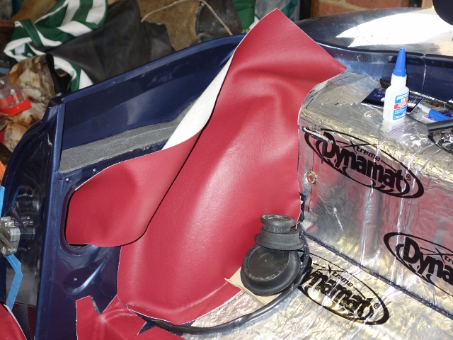
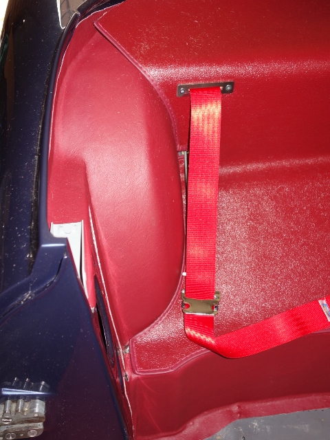
A finishing chrome escutcheon is mounted to the rear bulkhead which also acts as a guide for the belt. The slot in the bulkhead was made marginally larger than the one in the escutcheon to avoid the belt chaffing on the metal edges.

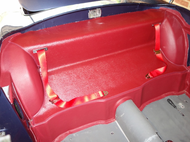
Overall I’m pleased with the modification although the belts are quite red! Burgundy webbing might have been easier on the eyes.

Apr 132015
 

Trimming wasn’t something I was looking forward to! My kit had been supplied by Suffolk & Turley. The only thing that appearred to be missing from the kits from all the various suppliers is any form of guidance, let alone detailed installation instructions!

It was very much a case of trial and error, never having trimmed a car before! So what follows is the approach that worked for me (and in some cases not!!).


A simple jigsaw puzzle!!

The kit consists of all the jute underlay, vinyl, Ambla, Hardura, vinyl covered panels and carpets. So one would assume it’s all fairly obvious how it should be installed. It’s the subtleties that are not explained! The trimming of the seats and central console were beyond my capability, so these had been supplied ready trimmed.

The initial focus was to get the car through an MOT and then do the interior trimming. However the decision to install boot-mounted inertia seat belts had put paid to that! They required most of the trim behind the seats to be fitted first.

The kit contained some 5mm open-cell foam underlay for the sills and rear wheel arches. The problem with this foam is that it isn’t very robust, losing its spring quite easily and disintegrating over time. I therefore decided to replace this with a denser closed-cell polyethylene foam, sold under the brand name Plastazote and available in a variety of densities and thicknesses.

As it’s denser, it won’t compress as much as the open-cell foam and so the edges would be more pronounced through the vinyl covering. I decided to purchase both 3mm and 5mm medium density sheets (Plastazote LD45) with a view to playing around chamfering the edges to get the finish I wanted. The decision was to use the thicker 5mm foam for the sills and wheel arches as it gives a softer, more luxurious feel. The lower rear bulkhead is normally just covered with Ambla (vinyl with an expandable knitted backing) but this would be covered with the 3mm foam first.

The trim covers recesses in the rear bulkhead and the wiring loom channels in the sills, which can become visible over time if the material pressed in. In an attempt to stop this, these areas were covered with reinforced cross weave tape. I also ran guide strings within the loom channel in case I need to run power to the rear of the car in future, eg for powering security/tracker devices.

Guide strings added – just in case! Then loom channels were taped over

Lower rear bulkhead
The 3mm foam was bonded to the rear bulkhead with a spray-on high temperature contact adhesive, purchased from Woolies Trim. It was more manageable to tackle it in two sections with the join above the transmission tunnel. Each section was then glued in three phases: the outer flat section, the concave area behind the seat and finally the small area around the transmission tunnel.

This approach allowed the non-glued section to be held against the bulkhead to make sure it was square across the full width before pressing the bonded area onto the bulkhead. The contact adhesive doesn’t allow a second attempt so it really does have to be right first time.

Each side was started at the sill end Next the concave section Foam in place … now the vinyl!!

I’d read other restoration websites covering the interior trimming, where they explained the vinyl should only be bonded to the perimeter of the foam underlay. So I followed this approach for gluing the Ambla to the rear bulkhead. Again I decided to tackle it in smaller manageable areas – the order as shown in the left photo below.

Areas and order of gluing the Ambla So far so good … section 1 bonded!

It was all going well up to section 3. To avoid wrinkles, the Ambla needs to be ever so slightly stretched as it is bonded to the foam. However, when the lower area (4) of the concave section was glued to the foam, the un-bonded area between (3) and (4) pulled away from the foam, as the Ambla contracted.

I tried to pull the Ambla away from the foam as soon as I realised but this just resulted in the latter being ripped apart. Aaaargh! Both the Ambla and foam were ruined. It took many messy hours to remove the remains of the foam, back to the painted bulkhead so I could start all over again.

The revised plan was to bond the whole contact area between the foam and Ambla. This time the process followed the sequence of bonding the foam, although in reverse – working from the transmission tunnel out to the sill, as the whole area needs to be covered by a single piece of material.

Revised area and order of gluing Bonding area limited by matching masking
The second attempt worked well The lower bulkhead trimming completed!

The main difficulty with the rear bulkhead Ambla is it needs to cover the body looms to the rear lights, fuel pump and tank sender. The sills have a recess to hide the looms but they stop just before the end of the sills so there is no tidy solution.

Sometime later, I was trying to find the best method of hiding the wiring looms as they travel around the lower edges of the wheel arches before entering the boot space. I couldn’t disguise the looms under the Hardura trim covering the rear bulkhead and so dug out the remains of the original trim to see if I could get any clues.

The (non-vertical) areas should first be covered by a layer of jute before the Hardura goes down and the excess bulkhead Ambla bonded over the jute. The trim kit didn’t include jute for this area, and indeed some for the rear face of the boot, so it was easily missed.

Although I had already fitted Dynamat sound insulation, it is much thinner than the original jute layer, and therefore not able to disguise the looms. The solution will be to fit some 1/4″ Dynaliner, with suitable channels left for the looms. The down side is that the excess Ambla will have to be lifted and re-bonded over the Dynaliner.

The Ambla was bonded over the looms Different bonding was needed against the Koolmat

The other issue was trying to bond the vinyl and Ambla to the silicone Koolmat, used to insulate the cabin from heat soak from the engine bay. I’d previously tested various adhesives such as contact adhesive and silicone RTV adhesive. Since then I’d found that Loctite produce a silicone surface preparation fluid (Loctite 770) which enables the ‘superglue’ Cyanoacrylate family of adhesives to bond to it. The combination of Loctite 770 & Loctite 406 superglue provided a very good bond and was used to secure the overlapping vinyl and Ambla to the grey Koolmat.

Sills
The 5mm foam and vinyl covering the sills were fitted, again in stages, working inwards from the outer edge. The foam was cut so there was a 1cm gap to where the sill meets the A & B-posts and also the floor. This was to provide a bare area of sill for the vinyl to securely bonded to.

For the gap to the sill edge, the chrome finisher was offered up. A gap of approx. 13mm would avoid foam being trapped under the chrome trim as it’s a fairly tight fit at the best of times. I didn’t want foam underneath to make things worse. The vinyl wraps around the sill lip and should be held in place by a number of metal clips.

A gap was left between the foam & sill edge First stage of bonding the foam underlay

I had a trial fitting of the clips using some scrap vinyl to see if they would stretch the vinyl as they were pressed on. No matter what I tried, I couldn’t get the clips on. I mentioned this to Suffolk & Turley when I was up discussing the hood – they don’t bother with the clips! They just run a bead of silicone RTV adhesive in the chrome finisher, wedging it in place while it cures. A tip I will be using once the sill door rubber is in place.

The approach of applying adhesive to the whole foam/vinyl contact area worked well with the rear bulkhead and so would be repeated for both the sills and rear wheel arches.

The vinyl was started by just bonding the 13mm strip at the sill’s edge. The aim was to anchor the vinyl in place as it would require cutting to shape as it was applied. The spray adhesive doesn’t give any room for adjustment once the two surfaces have been pressed together. So I thought it best to use the brush on Alfabond AF178 for gluing the sill edge and then pressing on the chrome finisher to hold it all in place, while it set.

Marking out the excess vinyl Excess can cause door rubber problems Bonding underneath the sill edge

Adhesive wasn’t applied to the underside of the sill edge, which allowed the vinyl to be pulled out to cut off any excess before being bonded. Too much excess can lead to problems fitting the sill door rubbers later on.

The edge of the vinyl is visible for a few inches; forward from the door opening to the A-post; reward to the B-post and 2-3″ along the outer face of the B-post (before it is hidden by a vinyl covered panel). The vinyl was doubled over to keep these edges neat and tidy.

The visible edges were doubled over to keep them neat

As the vinyl doesn’t stretch like the Ambla, a number of cuts were needed as it turns down towards the sill. There were a number of scares along the way where I didn’t think it was as smooth as it could be. The on-the-fly remedies often made matters worse. Fortunately the foam regained its shape overnight!

Again, bonding was done in stages Trimming around floor strengthener Sill vinyl almost completed

Overall I was quite pleased with the results. If it were to repeated, I would probably only leave a 5mm gap between the foam and the A & B-posts.

Rear Wheel Arches
The trimming of the rear wheel arches appeared to be much trickier due to the double curvature …. and so it would prove to be!! The pre-cut material has a very odd shape as it covers the wheel arch and a flat section underneath the hood mounting brackets.

Area covered by the wheel arch Ambla …. hence the odd shape of the trim provided

Numerous dry runs were done before deciding on how best to tackle it. Initially I started with bonding an outer section of the wheel arch, and the working down towards the lower rear corner. It soon became apparent that this wasn’t the way to go.

It left too much foam being pressed into an ever decreasing area, causing ruffling. Fortunately it was possible to cut out a section of excess foam and make a joint that would be invisible through the Ambla. This wouldn’t be an option when the Ambla is fitted.

Initial area bonded on 1st attempt Resulting in section cut out of foam

For the Ambla, it was decided that it would be best to glue a 2” strip down the shoulder of the wheel arch but stretching it as it went down. The reasoning was it would therefore reduce the excess material in the corner of the wheel arch.

Bonding this area first caused numerous problems!

Unfortunately this didn’t prove to be too successful and it was a real fight to get the lower edge glued without it puckering up along the join between the wheel arch and the bulkhead. Occasionally some Heath Robinson techniques were needed to weigh down the Ambla until the adhesive had dried. I shouldn’t have been surprised as it was not too dissimilar to the approach for the foam. A re-think was required for the other wheel arch!

Weighing down the edges to stop it lifting Bonding the lower edge worked better

The other tricky area was where it transitions between the curved wheel arch and the flat section. The Ambla just had to be stretched in the right direction to get a smooth finish.

For the second wheel arch, a 1.5” strip was glued along the lower edge. The foam could then be stretched up to the corner where it meets the top of the rear bulkhead. This ensures the Ambla is ripple free as it is being stretched over the curvature of the wheel arch. Initially this appeared to be a much better approach although it simply transferred the problems encountered later on to another area. The conclusion is that the wheel arches are just difficult to trim.


An Ambla covered wheel arch. Phew!

The trimming of the vinyl and Ambla was quite tricky and took over two weeks to complete, mainly due to putting off tackling the difficult areas and procrastinating too much! It would have been almost impossible to complete without the assistance of my trusty helper who patiently held the material up, while it was being smoothed into place and took the brunt of frustrations when things didn’t go as planned!

In hindsight, I wish I’d have bought shares in 3M with the amount of blue masking tape I ploughed through!!

Hardura and carpet fitting will be covered in Part 2 ….