
Several weeks ago I’d dropped off a box full of parts, including the heater and vacuum pipes, at the local powder coaters. Rather timely, they were ready for collection just before the bank holiday and one with fair weather forecast to boot! A good chance to crack on.
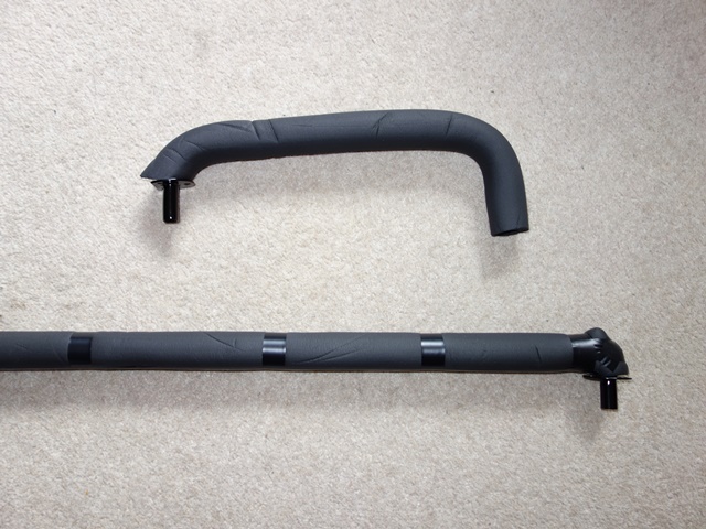
Fortunately you can’t go wrong with the orientation of the heater pipes and the vacuum pipes are fairly obvious. One vacuum pipe is straight (V2 in the photos) and one has a slight kink (V1) to bypass an entry point in the bulkhead. The entry point was originally blanked off so I assume this must have been for air conditioning or a fitting for LHD cars.
 |
 |
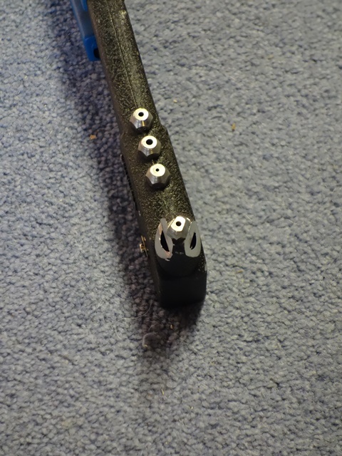
The fitting sequence is also obvious, working from the bottom up: H1, V1, V2, H2 and finally H3. My three heater pipes were new so I’d had a trial fitting of all the pipes and the bulkhead flanges so I wasn’t expecting too many headaches.
I’d picked up three tips from the E-Type forum from others who had gone through the same process:
- Insulate the heater pipes to stop unwanted heat within the bulkhead
- Use tape around the flanges to protect the paint when riveting
- Feed rope or cord through the pipe so, when pulled, it would force the pipe flanges hard against the inside face of the bulkhead
 All seemed sensible advice so I purchased some dense foam, pipe insulation. The other issue I’d already found was that the shoulder of the rivet gun was too wide to get the mussel onto the rivet head.
I spent a while looking for alternative rivet guns before someone pointed out the obvious; grind down the side of the rivet gun to reduce the width. A few minutes on a bench grinder and I was all set.
The first of many headaches was that I’d decided to route the vacuum and wiring cable for the EDIS Megajolt ignition within the bulkhead void. So this had to be removed temporarily to provide enough space to work. As I’d previously waxoyled the bulkhead, the whole process was a very messy business!
The tip of feeding rope down the pipes was really helpful. I fed a long length of garden wire down the pipes and, in Heath Robinson fashion, tied the ends behind me. I could then lean back pulling the pipes against the bulkhead while having my hands free for riveting.
Even so, I still managed to miss out the pipe flange when I riveted one end of the first pipe. The exterior flange was securely fixed to the bulkhead while the pipe was free to move!
 I ended up cursing the fact that I’d insulated the lower heater pipe. At least I probably should have used much thinner lagging. It made the fitting of the lower vacuum pipe so much harder and later the routing of the windscreen washer tubing.
Even though I’d trial fitted the pipes, when it came to actually fitting them, I had problems aligning the holes in the two flanges and the bulkhead for every single pipe. I’d passed a 3.2mm drill through each hole as the pipes had subsequently been powder coated but still there wasn’t enough tolerance.
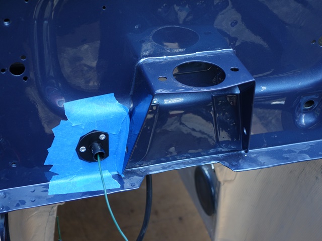 I’m also glad I taped the surrounding area as the head of the rivet gun tends to jump off the rivet when the pin snaps. I’m sure I’d have had several chips without it. In fact the only touching up needed was to one of the flanges but this was more to do with the adhesion of the Hammerite to the zinc plating.
Initially I’d only ground down one side of the rivet gun mussel. This was fine for the right hand ends of the vacuum pipes but useless for the gun orientation needed for the left hand side. Rather than stop and grind down the gun, I had a numpty moment and decided to fit the other heater pipes above before returning to finish off the troublesome vacuum pipes.
The pipe insulation was causing issues fitting the left hand side of the lower vacuum pipe so I thought I’d have to remove it. With the heater pipes fitted above there’s was no chance of getting at the vacuum pipes. So I just had to struggle on and finally managed to rivet them in place.
If I had the misfortune to have to do this again I wouldn’t bother with the insulation on the lower heating pipe, I’d waxoyl after installation and only move on to the next pipe once the lower one is completed. At last the long running saga of the bulkhead heater and vacuum pipes was over!!!

Now I can get on fitting the bulkhead components …..
Update: I’ve since read on the E-Type forum that uninsulated heater pipes can deliver sufficient heat to soften the surrounding waxoyl so it becomes runny and can drip everywhere. Therefore it’s probably is wise to insulate the lower pipe after all.

 The photo shows the difference in the bend radius between the two pipes. The tighter bend in the MkIII version means the pipe is perpendicular where it passes through the flange.
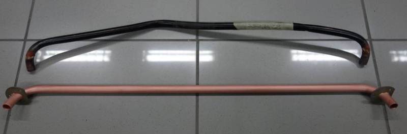
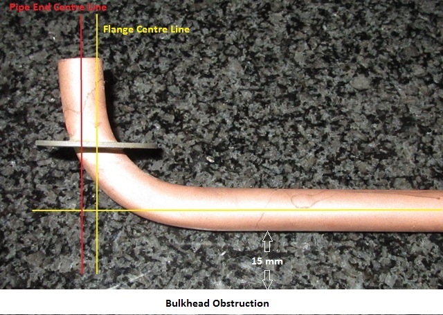 What I’d failed to mention was the bent pipe I’d supplied as the ‘template’ wasn’t the original pipe and I’d not trial fitted it. Like most of the repro parts it looks ok on the surface. That is until you get round to fitting it! The bends in the repro part weren’t tight enough and the flanges had been brazed mid-bend. It would never have fitted and so using it as template to replicate the require bend wasn’t such a good idea! The replicated bend on the right shows the probelm.