Jun 172015
 

I was keen to get the car roadworthy as soon as possible in order to drive it up to Nuneaton to have the hood put on. The difficulty at the moment is booking it in for work as it needs to coincide with dry weather!

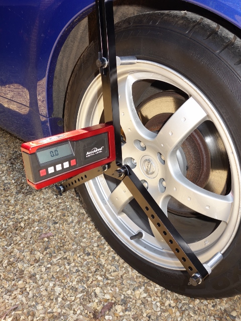
Fortunately the day of the MOT was a fine sunny day enabling it to be dropped off as soon as the garage opened. It had been booked into a local Jaguar specialist the following day to have the suspension geometry set up. There was a chance, with a following wind, that it might be road legal by the weekend!

After a few anxious phone calls during the day, it became clear that they wouldn’t have time to complete the MOT. They hadn’t even had time to get to the bottom of the front carb running far too lean. The car was returned to base and a second MOT appointment made for the weekend.


Back for MOT attempt 2

I decided not to cancel the wheel alignment the following day, planning a quiet route for the 2 mile journey that was not frequented by the Rozzers. Alas the car only made it about ¼ mile before conking out. After all the years of effort, it was a particularly low moment. I was certain it was due to fuel starvation and that wretched air lock.

Luckily it was possible to get the car back in 100 yard stints, by waiting a few minutes between each spluttering halt. The second MOT was essentially a repeat of the first with no progress made and the car returned yet again, without any work done either on the tuning or MOT.

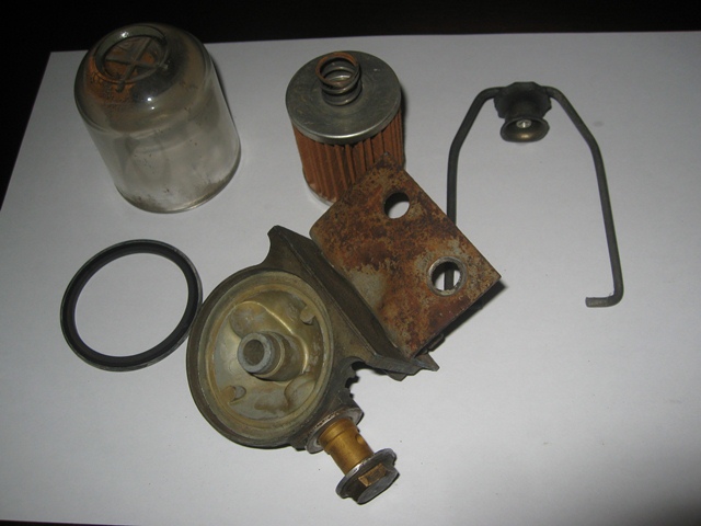
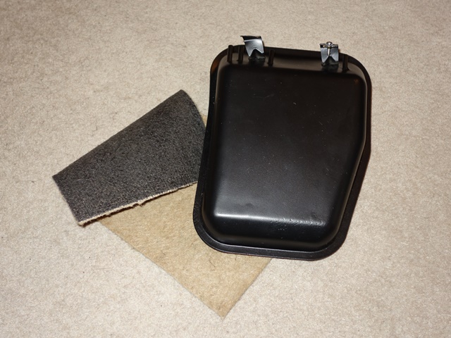
I took the opportunity to take the front carb off to look into why it was causing the front two cylinders to run too lean. The jet was properly centred but the float lever arm was found to be 3/16” off resting on the specified standard, a 7/16” rod.

More dismantling to investigate the front carb The float lever should rest against a 7/16″ rod

A few days later it was back for the third attempt. The revised plan was to leave the carb tuning as historic vehicles aren’t subject to MOT emissions testing and just do the MOT checks. As they say, third time lucky …. this time it proved to be just that! It had passed the MOT and was ‘road legal’ … the first time in over 20 years!


A hurrah moment!
Passing the MOT

Although it had taken three trips to achieve, I’m considering it as passing first time! However there were obviously issues to address before it could be considered truly roadworthy. In fact, the MOT brake test has to be done out on the road due to the limited slip diff. They only just managed to perform the test and get it back to the garage before the fuel starvation ground them to a halt!

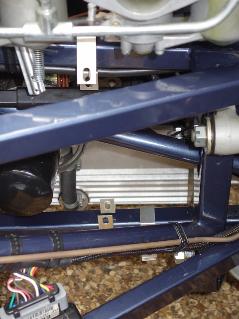
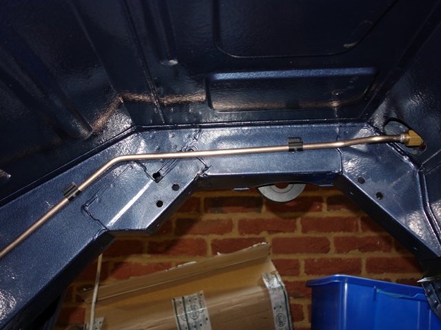
It was time to get some advice from my fellow trusted petrolists who had put in the IRS and come up with a plan. My worry was that it was the pipe running under that car that was a fault. Renewing it would require the IRS to be dropped and all that entailed – something I really wanted to avoid!

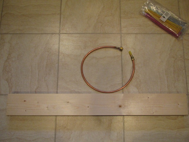
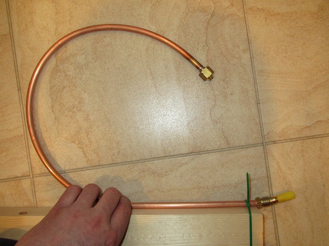
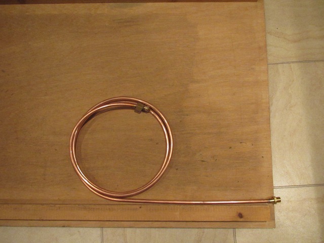
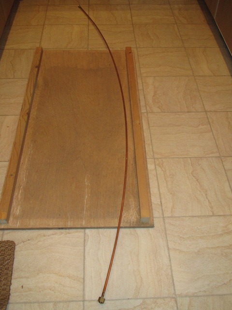
Their suggestion was to replicate the pipe run off the car using some flexible hose of the same bore. This would provide a more accurate flow rate that one could expect to achieve. If it is significantly different from the output of the under floor pipe, then it would point to this section being the root cause.

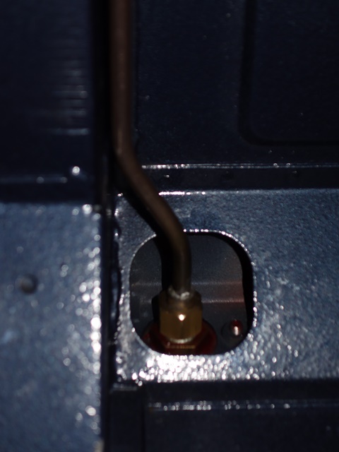
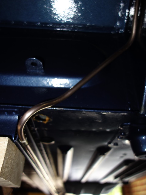
There were no kinks or collapsed bends in the pipe. The only other explanation was a blockage of some sort, but it’s a single length of (brand new) pipe which is open at one end and terminated at the other with a soldered connector that just mates with the bulkhead union. Hmmmmm …. could the soldered joint be causing a restriction and hence the reduced flow? It should be possible to poke a rod from the boot space through the union and into the pipe to get a feel to whether there was a restriction.

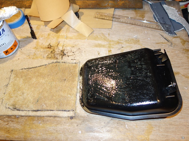
Rather embarrassingly, all my woes were of my own making. It wasn’t an air-lock, just my dreadful soldering! I’d almost completely blocked off the pipe by applying copious amounts of solder which had flowed into the bore. Worst still, I had compounded the error by not checking my handiwork before fitting the pipe.

My shocking soldering skills! Fabricated drill bush worked fabulously!!

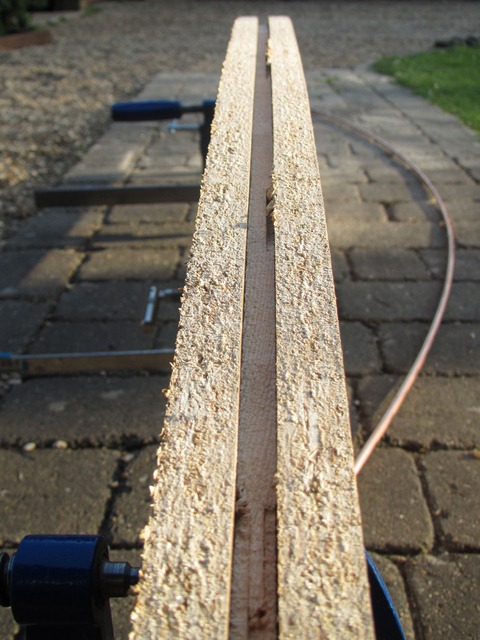
Further advice was sought on how best to removal it. Within no time at all, John had kindly arranged for a 3/8” BSP bolt to be machined/adapted to act as a drill bush to screw into the rear union. This would ensure the drill bit was perfectly aligned with the centre of the pipe and I would not be making matters worse by damaging the pipe itself!

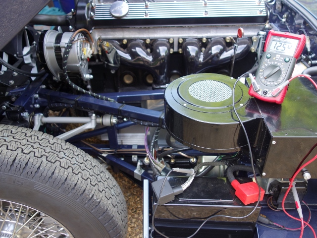
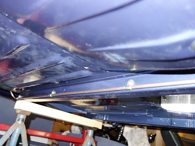
The flexible hosing that had been used find out the expected flow rate was rigged up to pass fuel back up the wrong way to blow out any swarf. The same flow rate test was repeated with the re-bored pipe.


Testing the expected flow rate

A flow rate of 1.5 litres was achieved with the flexible pipe and surprisingly an even higher rate of 1.75 litres per minute is now flowing in the pipe. Compare that to the 250ml before the re-bore! I’m just so happy and relieved we got to the bottom of the problem and resolved it!

Not surprisingly this has cured the fuel starvation problems and the engine is running much more smoothly. Although it still needs a good tune.

A couple of items were corrected as part of the MOT – even though I’d checked every suspension nut and bolt, I had still missed putting on the lock wire on the radius arm bolts. I’d also left off the jockey wheel for the water pump tensioner and the alternator fan was slightly loose. So these were corrected.

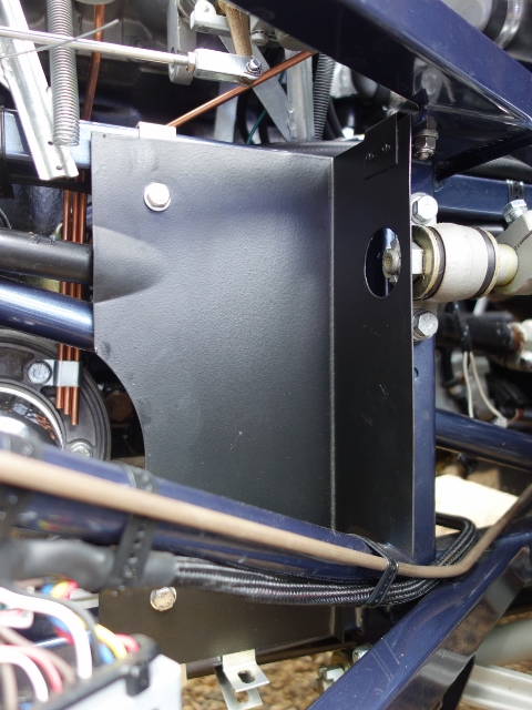
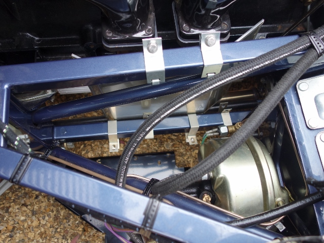
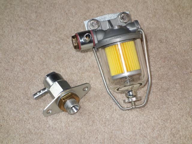
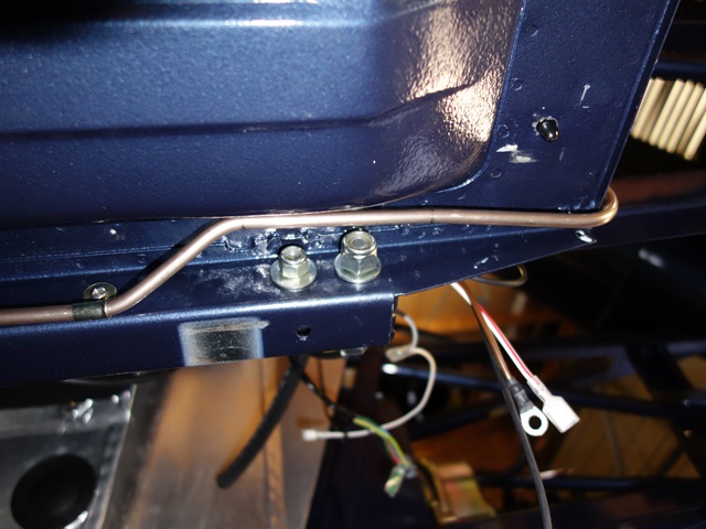
Other recommendations were to ditch the original nylon style fuel pipe in the engine bay in preference for some flexible rubber hose and always carry a fire extinguisher!! The nylon pipes are very hard and I had noticed occasional leaks if they were knocked out of position. I’d rather have a traditionalist tut-tut than run the risk of a fire!

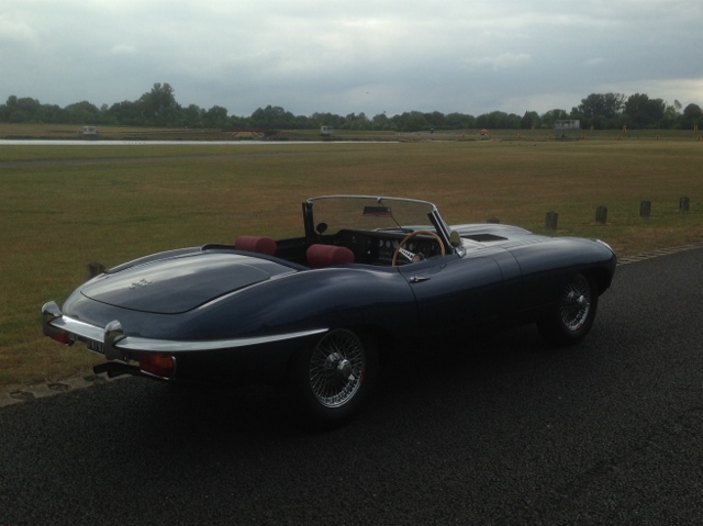
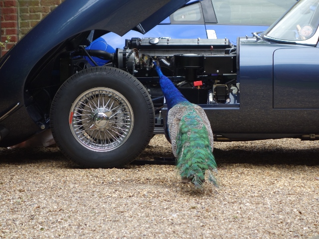
Even though the suspension geometry still needs to be set up, I couldn’t resist taking it out on the road for its first real spin. It was actually the first time I’d driven an E-Type and I wasn’t disappointed!

The first drive in the E-Type
Jun 162015
 

It feels as though the list of outstanding tasks is getting longer rather than shorter. So they have been prioritised into those required for the MOT and those that can wait. Due to the age of the car the MOT is essentially limited to checking the suspension, fuel/brake lines and lights. However, knowing the person doing the MOT, I’d asked them if they would cast a more critical eye over the whole car.

I’d been having trouble balancing the carbs and, although it’s not part of the MOT, I thought it best to have a second pair of eyes look over them. The front two cylinders are running too lean, even though all three carbs have been set to the standard reference point for tuning. So it will be tuned and the headlights aligned beforehand.

I also have concerns about the fuel flow. Last year the petrol tank had be put in-situ to just to start the engine for the first time. The tank was then removed to be painted and since then I noticed that the fuel flow seems to be rather low. Although I suspect I just hadn’t noticed the problem before.

Testing fuel flow from pump Comparing the fuel flows per minute:
250ml at front bulkhead in bottle,
2litres at rear bulkhead in jug

The measurements of the amount of fuel pumped in one minute was taken at the rear bulkhead union and then at the other end of the pipe at the union on the front bulkhead. Although it’s not really a valid test, as there wouldn’t be any back pressure at the rear union, it did provide a feel for the drop off in flow – 2 litres per minute measured at the rear bulkhead union and only 250ml per minute at the front bulkhead union.

Suspicion is that it may be due to an air-lock created in the pipes. However advice from the forum suggested that a pump in good working order would have more than enough ummph to purge any air locks. Some further checks will be done to get to the bottom of the problem.


Longacre Camber/Castor Tool

The intention was to set up the suspension geometry myself and so I’d purchased a Longacre electronic camber/castor tool and a Trackace tool for the wheel alignment. The camber/castor tool has three legs which rest against the wheel rim with an accurate inclinometer attached in the centre. However I wasn’t thinking things through and had completely overlooked needing clearance for the central spinners.

The prongs on the legs don’t have the reach so I’ll have to have some made up. Unfortunately the MOT centre no longer has accurate electronic measuring tools for suspension set up. This will have to wait until after the MOT.

For some reason one of the dash indicator tell-tale lights had stopped working and the fault traced to the switches in the indicator stalk. It was easier to take the whole steering column off and investigate further on the bench. A loose back-plate on the switch mechanism had allowed the indicator contact to move about and be bent out of shape. So it was easily rectified.

The clamping bolts on the upper and lower steering column’s UJs had been taken off to aid the removal of the upper column. However, I’d become side-tracked and had not refitted them before attempting to tick off another pre-MOT task … making sure the speedo drive was working.

Needless to say, as I was turning round, after completing a successful straight 40 yard speedo run up the drive, the lower column dropped out of its splines. All steering was lost, blocking a now busy communal drive!
Apart from being stupid, it was a rather timely reminder! The complete suspension parts list was used as a check sheet to ensure every suspension nut and bolt was revisited to make sure everything was correctly torqued.

Mudguards, shields and undertrays
The various mudguards, shields and undertrays aren’t strictly necessary for the MOT. However they were fitted, as the horn relay needs to be mounted on the LH mudguard. John Farrell had produced a good guide to the locations and orientations of the five different types of brackets:

Front frame bracket locations Five different bracket sizes

The first to be installed was the air in-take shield which is attached to bracket A at the top and B at the bottom. The leading face is also bolted directly to the frame. It’s worth noting that bracket E for the floor undertray needs to be put in place around the frame before the shield is attached. In fact it’s worth putting all the brackets in place before attaching any of the mudguards, shields and undertrays.

A & B brackets for air intake shield Bracket E for undertray is fitted
before in-take shield!

The bracket attachments to the frames are identical on both sides of the car, with the obvious exception of the air in-take shield. The torsion bar shields are attached by three brackets – the rear two have the tab with the bolt holes pointing upwards while the front one points downward. Note: the middle bracket on the LH frame is also used to secure the bottom of the exhaust heat shield.

Alternate rear torsion bar shield
& undertray brackets
Shield bracket also attaches bottom
edge of exhaust heat shield
Front torsion bar bracket (L)
and mudguard bracket (R)

The two floor undertrays are simply bolted in place. Although the right hand undertray has a cut out with a separate cover to provide access to the oil filter.

Left hand undertray Right hand undertray,
without oil filter access panel

There wasn’t any point in completing the fitting the mudguards because they will have to be removed to provide access to set the camber and castor. So at this stage they were only bolted to the sill end panel and attached at the front to a side frame bracket. At least this allowed the horn relay to secured for the MOT. Normally the alternator and aircon (when fitted) relays would also be attached to the LH mudguard, but by modifying the alternator it no longer requires a relay.

LH mudguard temporarily in place just for the MOT Location of horn relay. Alternator relay isn’t needed

Air Filter
I was regretting not trial fitting the air filter earlier. The new fuel pipe I’d made protruded too far from the face of the toe box, hitting the air filter. Fortunately it was possible to remove a short length from the filter end which resolved the fitting problem but re-introduced all the air bubbles causing the air locks.

It took a while to work out the best method of fitting the air filter element, canister lid and air plenum. Once the canister lid and rubber grommet are in place, there wasn’t sufficient access to pull the grommet up around the lip of the plenum chamber. Eventually I found the best solution was to connect these components off the car and then fit and remove as a single unit.

Filter canister was hitting the fuel pipe Adjusted fuel pipe now narrowly misses it Fitting canister lid first didn’t work

Alternator testing
Another task was to ensure the alternator was charging properly when the engine was running at higher revs. The outcome wasn’t as I’d hoped – it wasn’t charging at all, measuring only 12.5 volts! The converted alternator is now self-energising – the AL terminal, normally used for monitoring the alternator output via the ignition warning light, now provides a DC supply to power the field coil. Finding earth via the field coil through the 4TR voltage regulator.


Testing the alternator

The AL terminal was reading zero voltages at idle rather than the expected 14.3 volts! The voltage regulator controls the alternators output to avoid ‘run-away’ where its output would continue increasing until it burnt out the various internal components and/or windings. Increasing the voltage across the field coil increases the alternator output voltage, which in turn increases the field coil voltage.

The 4TR regulator acts as a fast-acting on/off switch. When the output of the alternator increases above a determined voltage (around 14.6v), the regulator switches off the current flowing in the field coil and therefore the alternator voltage drops. Once it has dropped sufficiently, it switches the current in the field coil back on and the alternator output starts to increase, until the cycle repeats.


A passing peacock offered
no helpful advice!!

Suspicion fell naturally on my modifications to the alternator and also the 4TR regulator, which are known to be fragile. A faulty voltage regulator can easily be identified by removing it and using a jumper lead to connect the F and ‘-‘ leads in its connector.

If it is faulty, starting the engine will cause it to start charging (indicated by the alternator output voltage or the battery gauge rising above the battery’s normal 12.3-4 volts) If so, the engine should be switched off immediately and the 4TR unit replaced. It was a great relief to find it was the 4TR unit that was at fault and not my handiwork! A replacement was ordered which confirmed the diagnosis and it is now working as expected.

Crossing fingers
I didn’t want to drill holes in the bodywork for side mirrors and so some clamp on mirrors have been attached to the window frames. That just about completed all the pre-MOT jobs.

Clamp on side mirrors fitted After all this time, it’s finally ready for the MOT!!

For the first time in several decades, 1R1421 hit the road …… on it’s way to the MOT centre! …. fingers firmly crossed!!

Feb 092015
 

Even though the engine was started last year, there were a number of outstanding issues and tasks to complete the fuel system. The most concerning was the new fuel tank didn’t fit! At the time, it was just left in situ and the fuel lines connected while the engine was fired up. Refitting had to wait.

Carburetter Overflows
First, however, was the replacement of the three carburetter overflow pipes. At some stage these had been replaced by shorter pipes. Functionally there was nothing wrong with them but they should come together near the oil filter and be held in place by small clip.

The short pipes will be replaced New pipes from Burlen Fuels
Either short overflow pipes had been fitted or the originals had been cut short  New overflow pipes are available from Burlen Fuels – very expensive for what they are!

Everything is available from Burlen Fuels although they offer two lengths of overflow pipe: 19” and 25”. The length of the shorter pipe would have been marginal for the rear carburetter so I opted for 25” pipes …. just in case. With hindsight, 19” pipes should have been ordered for the front two carburetters as the distances are much shorter.

I had decided to replace these once the engine had been fitted. While it would have been much easier to shape them when the engine was sitting on its trolley, I was concerned that guesstimating suitable clearances to engine frames etc would be too easy to get wrong.

Several hours later, ready for fitting The clip securing the ends of the pipes
 Several hours later, the pipes were ready for fitting

The only slight difficulty was the overflow for the rear carburetter as access was limited once it had been shaped. The jury is still out on whether it would have been better to do this job with the engine out!

New bulkhead fuel line
Another fuel problem encountered when the engine was started was the fuel line had gone into the filter housing cockeyed, causing it to cross-thread and leak. The temporary solution had been to reverse the fuel filter however the root cause was the bulkhead section of pipe, which needed to be remade.

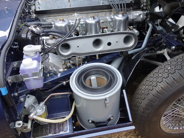
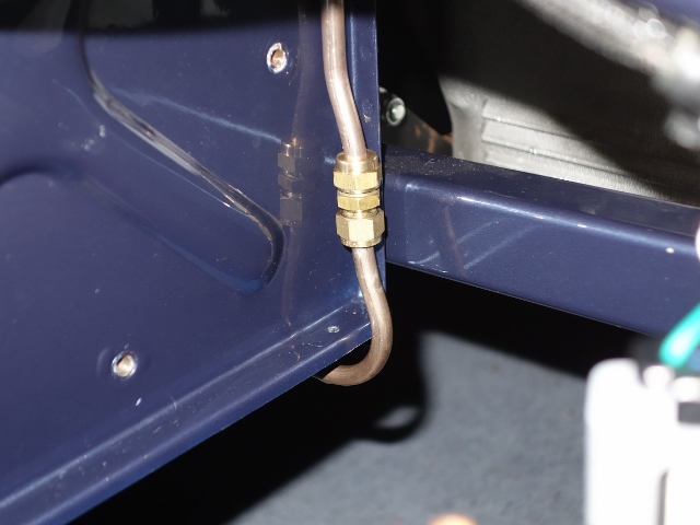
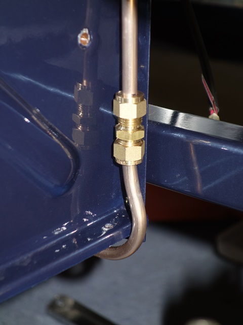
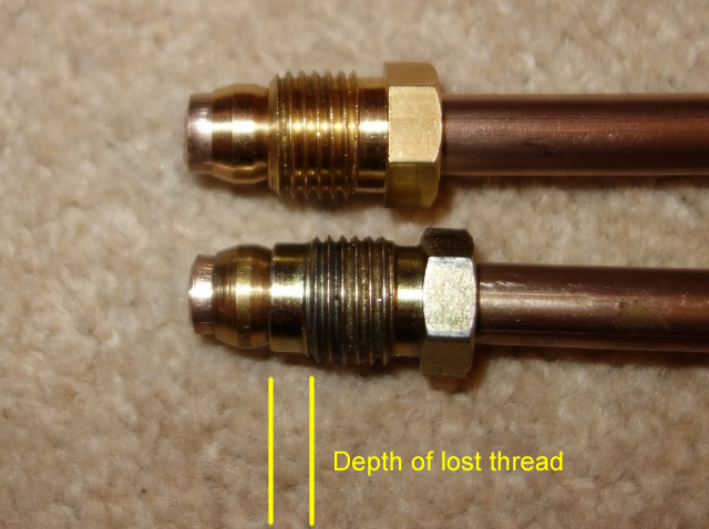
These earlier troubles had been caused by a combination of the pipe not being square onto the filter housing and the brass fitting supplied in the fuel line kit. The fitting had an un-threaded shoulder section which then only allowed a turn or two of thread to engage before it bottomed out on the olive. A replacement was found that was threaded to the end.

The vacuum tank needed to be removed to provide sufficient access to offer up the new pipe as it was bent into shape. I wasn’t happy with the original routing of this section of the fuel pipe, as the P-clip securing it to the bulkhead, pulled the pipe hard against the paintwork where there is an ‘X’ indentation in the toe-box.

Original routing Now routed higher on toe-box Upturn no longer fouls bodywork

By inverting the P-clip, so the pipe was supported by the clip rather than being hung from it, the pipe is routed above the ‘X’. The other problem that was cured from my first pipe attempt was the length of the downward run to the union had been cut too short, causing the upturn bend to hit the bodywork.

Installing the fuel tank …. 4th time lucky!
I take my hat off to the original fuel tank fitters, who must have developed quite an efficient technique for getting the fuel tank in place on the production line. Although, with trails and tribulations I had trying to get the tank securely fastened, it was becoming a less daunting challenge with each fitting attempt. Perhaps there is some truth in the joke about E-Types being built up around the fuel tank!

First a few minor tasks were completed. The sump was checked for pinholes as it is prone to corrosion and fitting the missing metal fuel filter at the base of the pick-up pipe. The tank and surrounding bodywork was then covered with plenty of sheets and masking tape to try and minimise the damaging the paintwork.

Fortunately sump was pinhole free Pick-up pipe – now with filter

The initial problem is the aperture of the boot space is less than the width of the seam-welded lip around the circumference of the tank. Tilting the front edge of the tank downwards doesn’t enable the lip at the rear to clear the flange for the boot boards.

There’s a gap in this flange where the boot lock attaches. So the only option I could see was to remove the lock and then tilt the tank sideways, feeding the lip through the gap vacated by the boot lock.

The most obvious approach was to raise the right side of the tank and feed it down to the left since the tank occupies the left side of the boot. However this first attempt failed as the sump attachment is proud of the base of the tank and comes into contact with the floor strengthening sections, halting progress.

So the opposite was attempted, feeding down to the right. The aim was then to shuffle the tank all the way across to the left once the flange had been cleared.

Yet just as it was nearing that point, it fouled somewhere else! It wasn’t immediately obvious what was causing the problem but eventually it was traced to the clip for the boot board. Fortunately it’s only riveted in place and could be removed.

The offending boot board clip Eventually the flange was cleared

Finally the tank was below the flange and could be manoeuvred into position once the various filler and breather pipes were attached. The boot lid drainage pipe caused quite a bit of aggravation as it had a tendency to spring out of place and push the tank away from the mounting points.

Corner bracket should
have captive nut
Breather tubes for
later S2 tanks
So near, yet so far

However, until now, I hadn’t noticed the replacement forward mounting bracket simply had a nut welded to it, rather than a captive nut within a cage. The lack of adjustability provided by a captive nut meant it was impossible to get the distance between the two leftmost mounting points to match those on the tank.

One of the mounting hole in the tank had to be enlarged by around 3mm to get the tank to fit The tank had to come out in order to enlarge the mounting hole in the tank by a couple of millimetres. Unfortunately I wasn’t able to rig up something to measure the difference in centre distances with any degree of accuracy. The tank was re-fitted but it was still a millimetre out, so it was back out for some more fettling.

This time it fitted! Well two of the three mounts did. The third bracket is moveable as it can slide in elongated holes and so would be doddle in comparison. How wrong could I be!

The original bracket had one stud missing and two of the other studs had lost most of their thread due to corrosion. It didn’t feel it was worth trying to salvage it as new ones are inexpensive. So I made the mistake of buying a reproduction bracket – not once but twice!

Damage to original bracket Neither repro brackets were usable

The first wouldn’t fit because the studs were too far apart to mate with the holes in the bulkhead. To make matters worse, I only found this out after it was powder coated. The second was ordered from a different supplier. The studs were in the right place but much smaller diameter. However, as with the previous bracket, they both just had a nut welded in place rather than the captive nut.

This mount requires both lateral and fore/aft adjustability to have any chance of alignment with the bolt. Lateral adjustment is provided by the elongated holes for mounting the bracket. The movement of captive nut provides the fore and aft adjustment. Neither of the repro brackets were useable.

Its times like this that I do get frustrated with all the suppliers – it’s just lazy ‘that’ll do’ mentality and often it would be as hard to get wrong as it would right. Although I really should have spotted the differences when they were purchased. The original one will be repaired, which is what I ought to have done in the first place. Another lesson learnt!

Fuel Sender – stumped but fixed
For some reason the low fuel light on the dash wasn’t working, yet the fuel gauge was fine. The fault was traced back to the fuel sender unit, which has a removable cover plate. So it was easy to gain an understanding of how it worked to control both the fuel gauge and warning light.

W & T terminal mechanisms Low fuel light contact strip

As would be expected, the unit uses a rheostat to vary the voltage drop across the fuel gauge and the warning light is simply a contact switch. However I hadn’t realised they were two completely separate circuits, sharing a common earth – the sender unit housing.

As the float arm rises and falls with changes in fuel levels, its pivot rotates through approximately 80 degrees. Two slider contact arms are attached to the pivot within the unit and therefore follow the same arc. They are also in contact with the sender housing and so are the electrical contact to earth.

Fuel Gauge
One of the sliders runs along the edge of tapered coil of resistance wire which is connected to the exterior T terminal. When the tank is full and the float is raised to its maximum, the full length of resistance wire lies between the slider and the T terminal – a total resistance of 196Ω.

When the tank is nearly empty and the float is at its lowest, the slider will have moved shortening the length of resistance wire between the two. At empty, the rheostat resistance is 18Ω. The fuel gauge is calibrated to display Full and Empty for these two resistance values.

Low Fuel Light
There’s a copper contact strip on the inside of the cover plate which has a small diagonal break in the copper so the two ends are electrically isolated from each other. The W terminal, connected to the gauge, makes permanent contact with one end.

When the tank is full the second slider arm is in contact with the other end of the strip and moves towards the W terminal contact as fuel is consumed. The slider eventually moves across the gap making electrical contact with the W-terminal, completing the path to earth and switching on the warning light.

I couldn’t work out why it wasn’t working. The multi-meter confirmed the internal connections were working correctly. Yet the switching wasn’t evident at the external spade connector. It didn’t make sense as a metal rivet connects the internals with the external spade terminal.

Checking with the multimeter confirmed that somehow the rivet and the external spade terminal were electrically isolated from each other. A dab of solder solved the problem but I still can’t fathom how they could not be in contact with each other.

Once it’s up and running, I’ll fill from empty to find out how many litres of fuel are in the tank when the light comes on.

The tank has since been filled from empty and it takes exactly 12 litres (2.6 gallons) before the warning light goes out. So there should be around a 50-55 miles range once the warning light comes on.

May 292014
 

The cars left the factory with untreated fuel tanks and so rusting from within was quite common. I wanted to seal the inside of the tank but needed to ensure that it was not of the PVC type, which is susceptible to hardening and cracking due to the increased percentage of ethanol used in modern fuels.

The other issue was avoiding the sealer blocking the small vent tubes again. Initially I’d looked at hot-dip galvanising but, after this was discounted, it came down to a choice of tank sealers from either KSB or POR-15. These both follow the same three step procedure; de-greasing, metal preparation and then application of the sealant.

In the end I opted for the KSB Gold Standard sealant. Although, oddly, the quantities sold are aimed more towards the motorcycle market. The tank needs to be rotated and rolled during all three stages of treatment to ensure all the surfaces are covered, including the baffles. Therefore it needs to be sealed to avoid leaks.

I didn’t want to ruin the final cork gaskets and so made up some silicone ones, using the left over two-part silicone used to create the mould for the heater vane.

Making silicone gaskets Masking tape retained the silicone Fuel sender gasket

The cover plate with the tube down to the fuel filter could be masked fairly easily to stop it being coated with sealant. Therefore it could be used to seal its hole in the tank. However the fuel sender couldn’t be masked effectively. So, to coating the moving and delicate parts, an aluminium disc was knocked up as a replacement.

Sealing the filler neck was slightly trickier as I couldn’t get hold of a large enough bung. A replacement bath plug from B&Q just about did the job, requiring some additional help from duct tape.

The KSB tank sealer is reasonably fluid which allows it to cover the internal surfaces fairly easily. As a result I concluded that periodic blasts of compressed air would be sufficient to stop the internal ends of the vent pipes from blocking.

Compressed air to clear vent tubes Sealed tank with de-greaser and metal prep Finally the sealant is applied

The first stage involved applying a warm diluted solution of KSB’s AQUA product to thoroughly degrease the tank. The tank then needs to be rinsed and completely dried throughout before applying their ‘Rust Buster’. Again, this needs to be rinsed and the tank completely dried before moving on to the final stage of applying the sealant.

The AQUA and Rust Buster are essential just a branded degreaser and a phosphate acid solution, to convert any surface rust. Therefore cheaper alternative options are available for these steps.

The Gold Standard tank sealer was then be poured into the tank and the tank slowly rotated to ensure all the surfaces are covered. A slow methodical approach to rotating the tank was definitely better than trying to shake the tank. The curing process doesn’t start for at least 30 minutes when it slowly becomes more viscous so there is plenty of time to get good coverage.

Compressed air was periodically blasted down the vent tubes to stop them blocking as well as every time the tank was turned. After about 30 minutes the unused sealant was drained from the tank before it started to thicken due to the curing process.

All surfaces need a light coating Draining the excess tank sealant Repainting the exterior

Unfortunately the various seals weren’t water tight so some phosphoric acid escaped over the painted exterior finish. The weak acid left light run marks in the paint which could probably have been polished out but I decided to repaint the tank with some POR-15 gloss chassis paint.

The completed tank sealed and re-painted

Testing the fuel pump

 Fuel Pump, Fuel System  Comments Off on Testing the fuel pump
Jul 092013
 

It has been a long time since the fuel pump had been rebuilt, converting it from mechanical to electronic actuation in the process. Burlen Fuels offer an electronic conversion kit to overcome the known issues with point corrosion with the mechanical set up. While it would have been cheaper to buy a new pump, by reconditioning/converting it, I would gain a much better understanding of how it worked which might prove useful if there are issues in the future.

The electronic set-up had already been tuned to its maximum pumping speed, by rotating a Hall Effect fork. I just needed to check the flow rate was close to the designed 2.4 pints per minute by bench testing it with some paraffin before putting it on the car.

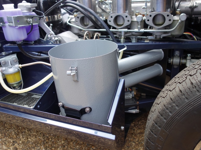
The pump raced when it wasn’t under load. So far, so good! However when the inlet pipe was placed in the bucket of paraffin it didn’t quite go as planned. It stopped immediately! I tried retuning the electric circuitry by repositioning the Hall Effect fork through its full arc of travel but it still refused to pump. It was a bit gutting having spent all that time and effort.

The technical department at Burlen Fuels thought it might be due to reverse pressure which would naturally slow the pump down. Although I wasn’t convinced as the outlet was simply pumping back into the supply bucket. I was running out of options and was starting to regret not buying a new pump!

I refitted the magnet attached to the end of the diaphragm spindle in the hope that this might be limiting its travel and therefore the strength of the pump. Eureka – the pump continued under load but at a much reduced rate, which would be expected.

The proof would be in the achieved flow rate which, over three tests, averaged out at 1.6 litres or 2.8 pints. Phew!

I was now happy that the pump was in working order and could be refitted to the car.

Jun 052013
 

The fuel lines within the boot space are made of a hard, opaque, white nylon and exit via a union mounted on the far right of the rear bulkhead. Metal piping is then used between the union, around the rear axle mounting panel and along the underside of the chassis, to the fuel filter within the engine bay.

Fuel filter just needed to be cleaned up and the filter replaced Dismantling revealed only small amounts of deposited fuel residue

The filter and union just needed to be cleaned up. So the alloy body had the ultrasonic cleaning treatment to remove the fuel residue and the other parts zinc-nickel plated. Leaving the difficult part of bending the Cunifer fuel pipe ….

Ultrasonic cleaning brought the filter lid up nicely Cleaned and re-plated; the rear bulkhead union and filter assembly

A 5/16″ diameter pipe is used for the fuel line so it is less forgiving than the brake pipes if minor tweaks are needed. The difficulty is that the entire section around the rear suspension cage needs to be bent into shape before it can be offered up. This involves bends in a variety of different planes, a sharper bends to then pass along the underside and ensuring the pipe passes through two retaining clips.

Fortunately I still had a slightly deformed original pipe to use as a template otherwise it would have been an altogether harder task. Again, as with the brake piping, I deviated from the original routing around the bolts for the torsion bar reaction plate. The only bit I’m not entirely happy with was the small section of pipe from the inline union in the engine bay to the filter which ought to be more horizontal. Still, it’s hidden by the vacuum tanks so shouldn’t stand out.

The good thing is that, now this pipe is in, the completed rear suspension cage can be fitted. Half way to a rolling chassis!!

Below are a few photos of the pipe routing:

Bulkhead fuel union Around rear suspension Double curve to underside

5/16 Cunifer pipe is used for the external piping from the rear bulkhead union to the filter in the engine bay

From the union, the pipe follows the IRS mounting section

A double bend is needed to clear the welded floor/bulkhead flange

P-clips secure pipe to chassis Avoiding reaction plate bolts Double bend to inline union

The pipe then runs underneath the car, attached to the strengthening section with P-clips

The pipe was diverted around the reaction plate mounting bolts to provide access for spanners

Another double bend is needed to pass around the welded floor/toe box flange to an inline union

Inline union to filter

Finlly from the inline union, the pipe passes behind the reservac tank (not fitted yet) to the fuel filter

Mar 212013
 

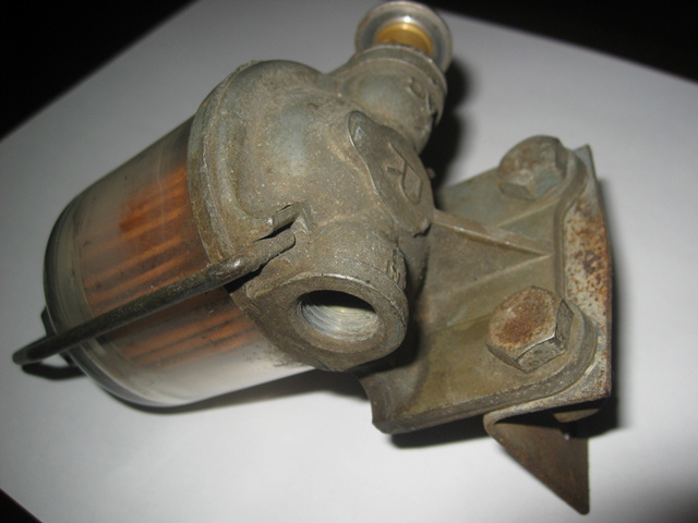
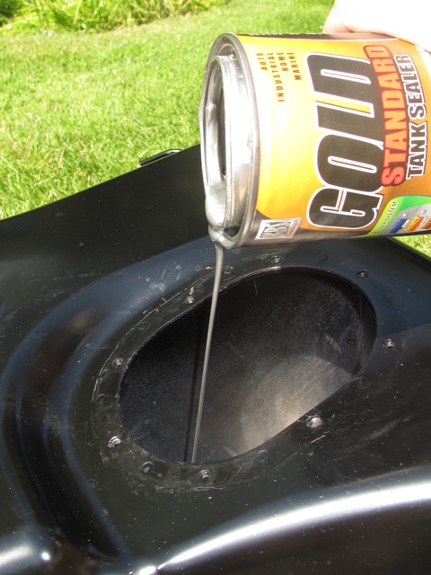
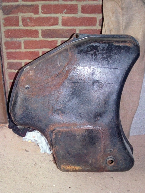
The fuel tank has been another area that hasn’t gone as smoothly as I had expected. At first glance the tank appeared to be fine however the problems were only revealed once it had been removed.

Over time the untreated tank had rusted through which is a common problem. It had been repaired by welding several replacement patches but the weld seams weren’t the best and had started to corrode quite badly.

My concern was the thickness of the tank, or lack of it, either side of the weld. I think water that had entered the tank must have been settling in the various troughs in the weld so it was again rusting from within.

As luck would have it, there was an advert in a Jaguar magazine for an unused later S2 fuel tank. The S1 owner had purchased the tank unaware that the design had changed from a single breather pipe to three from chassis number 1R1393, some 28 cars before mine! In fact I wasn’t aware of a difference until I’d read his advert.

The three breather pipes were introduced with the addition of the expansion tank into the fuel system, late in the production run of the S2 cars. I think this is why it’s not referenced in any of the manuals.

A number of owners on the E-Type forum have reported running problems as a result of fuel starvation. Insufficient venting of the fuel tank was enabling a vacuum to build in the tank, acting against the fuel pump. A common remedy is to drill a small hole in the fuel filler cap. I can’t see how the addition of an expansion tank would alleviate this problem. The S1 and early S2 tanks were just vented directly to the outside rather than via an expansion tank. So fuel starvation issues may still be a problem …. but more of that later.

The replacement tank been already been treated with the white PVC type tank sealer. However, during the time it had been kept in dry storage, the sealer had started to crack and come away in sheets. It would all have to be removed otherwise it would quickly start to clog the fuel filters.

I started to research the different types of tank sealers on the market, mainly to find out the best method to remove the sealant used in my tank. The conclusion was that the PVC type sealers have very good coverage but don’t fill holes or seams well and have poor film strength. I’d found that out to my cost!! Most recommended using a paint stripper to remove it.

I had a large tin of Nitromors lying about so I gave it a go and poured it into the tank along with some nuts and bolts. The latter providing a mechanical method of dislodging loose bits of sealant. The problem with modern Nitromors is that they have changed its properties to a more gel like consistency rather than liquid. As a result it wasn’t very good at getting into the baffled areas.

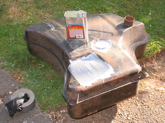
I then switched to Por-Strip which was better but didn’t reach much of the internal baffle surfaces. I needed a new approach.

One of the local powder coating firms offers a burn-off service but they didn’t want to do it as they were concerned the temperature would melt the brazing. Eventually I took it to a furniture restorer who was able to dip the tank. However the borescope revealed that there was still quite of a lot of sealant stubbornly attached.

I think paint stripper just softens the sealant which then becomes a sticky goo. Unless it is successfully removed immediately it simply sticks back to the tank surface as it dries out.

Like most troublesome issues, I put it to one side to have a ponder. I would tackle it at a later stage!

I recently found out that the PVC coatings can also be removed by dissolving in either Acetone or MEK (Methy Ethyl Ketone). Spurred into action once more, I ordered a small quantity of Acetone and added some sealant flakes to confirm it worked. 20 litres of Acetone have now been ordered and the tank is going to receive a thorough soaking at the weekend. Fingers crossed!

It still leaves the dilemma of how to treat the tank to avoid it rusting from the inside out. Not only that but it dawned on me that swilling around sealant inside the tank might cure the rusting problem but would be guaranteed to cause another. I’d realised that the PVC sealant had done its job and sealed the ends of all the internal pipes for the expansion tank connections.

Unless the Acetone can unblock them, I might have to resort to removing the brazed joints and withdrawing the pipes. I’m now wondering whether tank sealants might be the cause for some of the people suffering from fuel starvation problems.

 Posted by at 7:27 am
Mar 202013
 

A fuel expansion tank was added during the production run of the Series 2 cars, located in the boot space on the LHS rear wheel arch. The expansion tank is vented to the outside and so it’s internal pressure is always equal to the current atmospheric pressure.

Thermal expansion of the fuel increases the pressure in the fuel tank relative to the pressure in the expansion tank. As a result, fuel passes from the main fuel tank to the expansion tank until the pressures are equalised. As fuel is consumed or when the fuel contracts due to cooling temperatures, the pressure in the fuel tank decreases relative to the expansion tank. Any fuel in the expansion tank is then returned to the fuel tank as the pressures equalise once more.

Note: I have subsequently seen a Jaguar Service bulletin which indicated that fuel passes back from the expansion tank to the fuel tank by gravity, not pressure. Although with such a small bore for the breather pipes, I would have thought it’s probably a combination of gravity and pressure to overcome airlocks.

When the expansion tank was removed, I carefully labelled the various pipes between the two tanks with masking tape. For some reason I wrote the descriptions on the masking tape in pencil, which didn’t stand the test of time and were illegible by the time it was ready to be refitted. A lesson learnt!

A piece of 6mm jute was bonded to the tank as a protective layer between the tank and the wheel arch. However the bond was greater than the strength of the jute and so would need replacing. It’s available from most of the re-trimming firms and was bonded using the same AF178 contact adhesive used for the heat insulation.

I now had to work out how to make the connections between the two tanks as it’s not covered in any of the manuals available. The expansion tank has four outlets and the fuel tank only three. The additional outlet on the expansion tank is for the vent which exits to the outside via the boot drainage pipes. Although I believe the vent is connected to the emission control system for cars supplied to the USA.

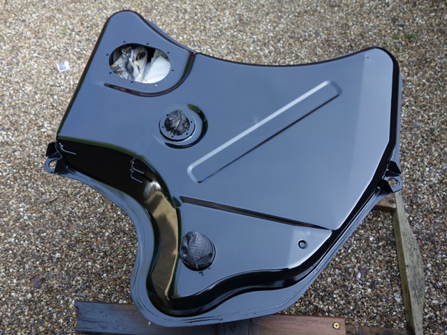
The first task was to work out the difference between the four internal pipes in the expansion tank. I used a length of garden wire with the end bent over to form a hook. This enabled the wire to be jiggled so that the hook engaged with the end of the pipe inside the tank and therefore could determine the internal length of the pipe.

Three of the pipes ran from the bottom to the full height of the tank while the fourth terminated as soon as it entered the tank, as depicted in the photo. The short red pipe (A) is at the bottom of the expansion tank and therefore must be for returning fuel to the main fuel tank. So I would expect this to be connected to a pipe which terminates fairly high up at the top of the fuel tank.

The other two blue pipes (B and C) terminate at the top of the expansion tank and so would be for the pipes passing fuel from the main tank to the expansion tank, when the main tank is full to the brim. The fuel entering the expansion tank via B & C would then fall to the bottom, to be returned via pipe A when the pressure in fuel tank reduced.

I would therefore expect B & C to be connected to pipes which would normally only be submerged in fuel when the tank is full, ie terminating at the very top of the fuel tank. It was now time to get the USB borescope out to investigate the fuel tank as ends of the pipes are hidden due to the internal baffles.

In fact the corresponding red pipe A in the fuel tank was easy to determine as the end of the pipe end can be felt via the large oval opening. The borescope did confirm that the other two pipes terminated at the top of the tank. The end of pipe A turns downwards for about an inch. I assumed two pipes are needed to pass fuel to the expansion tank due to the baffles. It shouldn’t matter how the B & C outlets are connected, ie B to B or B to C, as they are both performing the same role.

Anyway, assuming my logic is correct, I think I’ve worked out the correct connections!!

 Posted by at 10:35 am
Jun 172012
 

The fuel and brake lines were other items that were to be replaced as a matter of course during the rebuild. I had intended to purchase lengths of piping and make the individual pipes myself. However the cost of decent pipe flaring tools, able to achieve consistently good joints, are considerably more than complete kits.

So I’d purchased a brake kit from Automec, a similar fuel line kit from Hutsons and a pipe bending tool. Both kits were supplied in copper rather than bundy or cunifer which is closer to the original look. So I’ll have to see how they look on the car and I may revert to fabricating my own in cunifer; an alloy of Copper (Cu), Nickel (Ni) and Iron (Fe).

More importantly, I subsequently found out that copper brake pipes are banned in countries like Australia and the US, where cunifer is the norm. Apparently the copper pipes are susceptible to work hardening over time which can lead to fracturing. The introduction of Nickel and Iron addresses this problem. I think more research is needed especially as it’s a safety issue.

Back to the pipes … the problem with the kits is that they are fabricated from coiled piping. In order to get neat, straight pipe runs they need to be straightened before forming into the correct shapes.

I found an article on an American car site with a rather over-engineered process for straightening coiled fuel pipes. I had a spare afternoon so I thought I’d give it a go. The main point is that the coiled fuel pipe should only be straightened/bent in the same plane as the direction of the original coil.

The first step is to lay the coiled pipes on a flat surface and uncoil them against a straight edge, therefore ensuring additional bends in other planes are not introduced. Once released, the pipes will spring back to some extent in the direction of the original coil so the pipes will now form an arc.

Trial run with the shorter engine bay 5/16″ fuel pipe

Long boot to engine bay 5/16″ fuel pipe

The second step involves deforming the pipes beyond a straight line so that this time, when they spring back, they (hopefully) return to a straight pipe. As it happens, the pipes need to be bent beyond the straight line to exactly the same radius as the arc of the now uncoiled pipe.

I used two pieces of old shelving and some 9mm cladding, the latter would act as channel down the centre of the form. I guess you could just use one board against a flat surface.

The radius of this arc is determined by the pipe thickness and the diameter of the original coil. Therefore, for a given pipe size from the same original coiled length, the arc radius will be the same regardless of pipe length.

The final step is bending the arced pipes over the form. Starting at one end, position the pipe arcing away from the form but in the same plane. Then bend the pipe around to produce a straight pipe when released. However be careful not to allow the pipes to rotate when doing the final step.

I thought the results were quite good for a pleasant afternoon spent taking a sledgehammer to crack a nut!