
One of the safety features introduced during the production of S1 4.2 cars and carried over to the S2 was a collapsible steering column. The lower section of the steering column housing consists of a lattice structure. In the event of an accident where the steering wheel is impacted with sufficient force, the column’s two upper mounting points are designed to shear and the lattice structure collapse to absorb some of the impact and allow the steering wheel to travel forward.
To enable the column to collaspe, the total length of the inner steering shaft must also be allowed to shorten. To achieve this, the inner shaft is comprised of two sections which are fixed in position by two nylon pins. An impact will cause the pins to shear, allowing the two halves to slide over each other.
The same design is used for the lower steering shaft, connecting the steering wheel column to the rack. Therefore some care needs to be taken when handling and refitting the steering shaft to avoid any heavy impacts and the use of mallets to fully engage the splines!
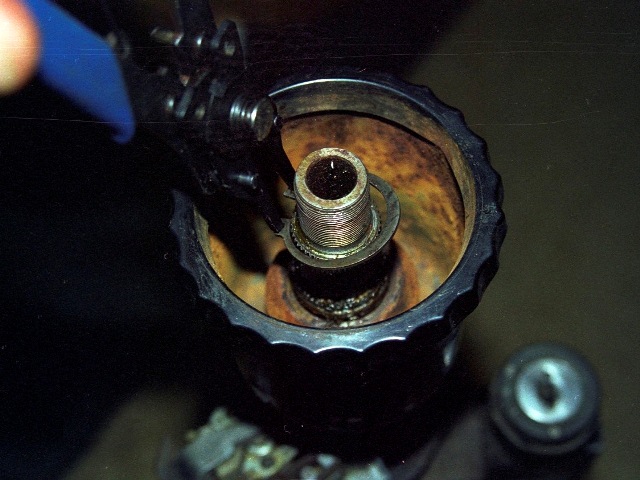
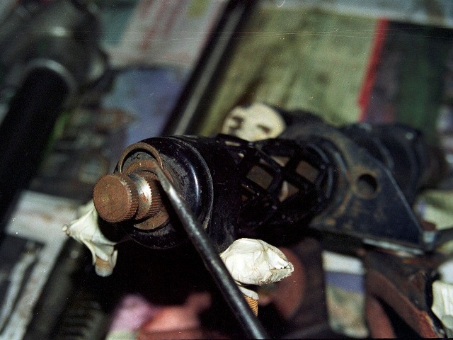
The steering wheel’s fore and aft position can be adjusted by rotating the large black cup-shaped locking nut to release the clamping pressure on a split collet, thus allowing splined inner columns to slide over each other.
Another difference between the early S1 and later cars was that the horn was now activated by pressing the indicator stalk rather than the E-Type motif in the centre of the steering wheel. I assume this might have been partly due to having to make the steering column collapsible but it does simplify the dismantling.
The E-Type motif is normally held in place by three grub screws in the aluminium steering wheel boss but for some reason a previous owner had also glued it in place! It’s removal provides access to the nut clamping the boss against a split cone located in a recess in the inner shaft.
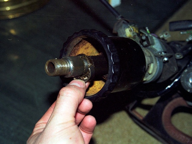 I was surprising how much force was needed to loosen the nut. It was necessary put on full lock and then use an extension tube over the socket wrench handle to get enough leverage.
It’s just as well I didn’t take it off the car as a complete unit as it would have been a struggle without having the resistance of the steering rack at full lock.
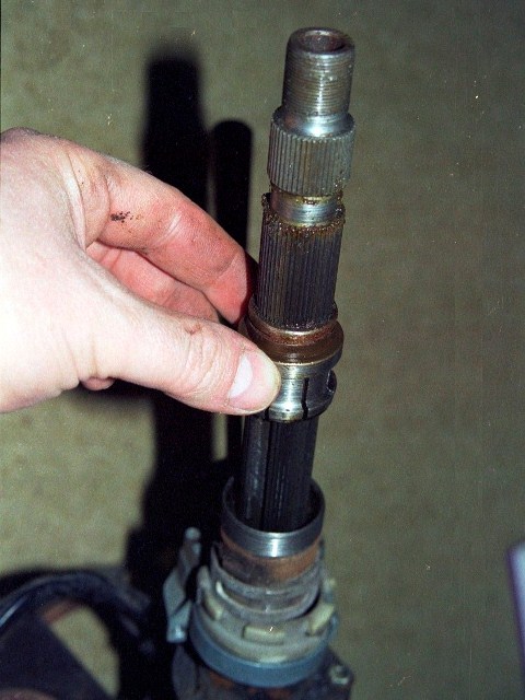
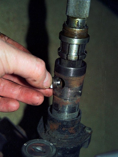
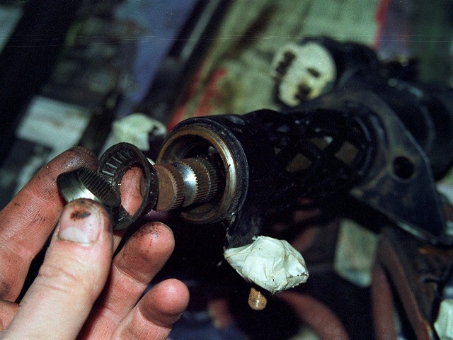
As mentioned, the adjustability in the steering wheel position is achieved by two splined inner columns being able to slide over each other. Their travel is limited by a ‘stop button’ which is screwed through the female inner column and locates in a machined slot in the male inner column.
The steering wheel is then locked in place by a splined split collet, which is attached to the underside of the cup-shaped lock nut by a circlip. When there is no clamping force, the male column is free to move on the splines. However, by screwing the lock nut onto the female column, the collet is compressed and clamps the two inner shafts together.
Once the circlip is removed, the lock nut can be unscrewed and withdrawn, followed by the collet. Next is the stop button to allow the male inner column to be removed.
 |
 |
 |
The female inner column passes through the indicator mechanism, attached to the main steering column housing by a semi-circular bracket. Automatic indicator cancelling is built into the mechanism by the use of a control striker attached to the inner column.
 |
 |
The striker interlocks within a white nylon ring in the indicator mechanism so that the ring rotates as the steering wheel is rotated. Protrusions moulded into the nylon ring hit ‘cancelling’ cams which force the indicator stalk back to its non-indicating state when the steering wheel returns towards the straight ahead position.
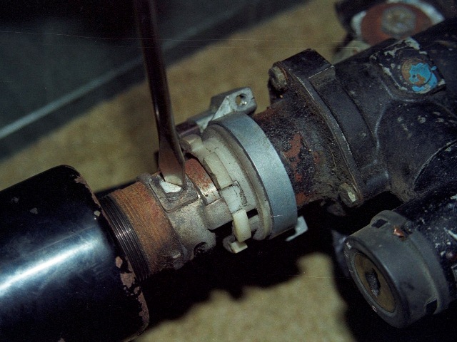
All that remained was to liberate the female inner column from the steering column housing. The inner column rotates in roller bearings at each end. The lower bearing is held in place by a retaining cover which itself is secured by a circlip and a number of washers. One of which is a wave or spring washer which takes up any free play and provides a small amount of load bearing capacity.
Once the cover and washers are removed, the splined inner bearing race can be slid off the inner steering column and the roller bearing withdrawn. The outer bearing race is simply a press fit into the steering column housing.
 |
 |
 |
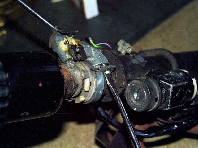
The steering column housing’s upper end cover can be removed by releasing the three small retaining bolts.
 At which point the key needs to be turned in the ignition to withdraw the steering lock. This enables the female inner column to be removed.
The ignition switch and steering lock housing is secured to the main housing by a security bolt, which needs to be drilled out in order to remove the lock. The security bolts are designed so the hexagonal part used to tighten the bolt shears, removing the ability to remove it easily.
It’s worth noting that it would be possible to remove the whole inner column as a single unit, even keeping the steering wheel in place, by:
- Removing the lower roller bearing circlip and withdrawing the washers, cover and inner race
- Undoing the three bolts securing the steering housing’s upper cover
- Turning the key in the ignition and withdrawing the entire inner column
This would enable the roller bearings to be replaced without resorting to dismantling the entire steering column.