The brakes have been connected and plumbed in for quite a while now. The system only had to be filled with brake fluid and bled, so I had assumed the brakes were essentially complete and wouldn’t be noteworthy. I should have known by now that was almost certainly going to be wildly optimistic …
I had dithered on the type of fluid to use, glycol base or silicone, changing my mind almost on a daily basis before finally making the decision to stick with glycol based DOT4 fluid. The ‘this is absolutely my final decision’ was subsequently reversed to silicone following an interesting article on the subject sent to me by Chris Jackson, whose restoration is being covered in the E-type Magazine.
DOT5 Silicone Brake Fluid ![]()
The debate regarding DOT4 (Glycol) verses DOT5 (Silicone) seems to be quite polar in nature. A bit like Marmite – people are either for it or hate it and never the two shall meet! At the time I’d just been working through fixing leaks in the cooling system. Reports of leaks from weeping hoses and splitting repro reservoir bottles are all too common. The thought of brake fluid leaking onto the paint work and remaining undetected paid a significant part in opting for silicone.
However some have raised concerns that silicone fluid might cause rubber seals to swell. Possibly but the composition of the rubber seals has changed over time, with natural rubber no longer used. Modern rubber should now be compatible with all types of fluid.

Automec DOT5 Silicone Fluid
The manufacturer’s blurb suggests silicone fluid is a ‘fill and forget’ solution but I think this is a little wide of the mark as water will find its way into the system. As it doesn’t mix with the brake fluid, it would then pool and cause local corrosion so I’m still planning to replace the silicone fluid periodically, although less frequently than would be the case for DOT fluids.
Apart from the additional expense, the down side of silicone is that, when it is agitated, it has a tendency to absorb tiny air bubbles that are not visible to the eye. This can cause a spongy pedal as the bubbles compress under braking. The simple solution is to leave the fluid to settle overnight before bleeding the system, although that would be more problematic if it ever had to be refilled on a trip.
All the compression joints were checked and tightened. Now the front calipers were bolted to the uprights, sufficient torque could be applied to the bolts clamping the two caliper halves together. Correct torque settings are not published but a brake refurbishing company recommended to torque the 7/16″ diameter bolts to 70 lb-ft and the 3/8″ diameter bolts to 40 lb-ft. I’ll need to keep an eye out for any initial issues.
Remote rear bleed kit
 and Stevson Motors (inner)")
Stevson & Fosseway kits
Another of Chris’ suggestions was to fit one of Fosseway Performance’s remote bleed kits. The standard bleed valves are hard to reach at the best of times, so moving them to a more accessible position on the IRS cage is quite a popular modification. In fact I’d already fitted a similar kit sourced from Stevson Motors prior to installing the IRS unit.
My kit was definitely more agricultural than engineered so I had been a little disappointed when it arrived. The mounting brackets were just pieces of brass sheet that looked as though they had been hand drilled and then bent in a vice.
Still their function is fairly basic and the aesthetics is not a great issue, being tucked up underneath the car, so I had fitted the Stevson kit. It was only later, when I was working underneath the car to re-fit the handbrake cable, did its design start to irk me. My patience was wearing thin after catching the sharp corner of the brass bracket for the umpteenth time.
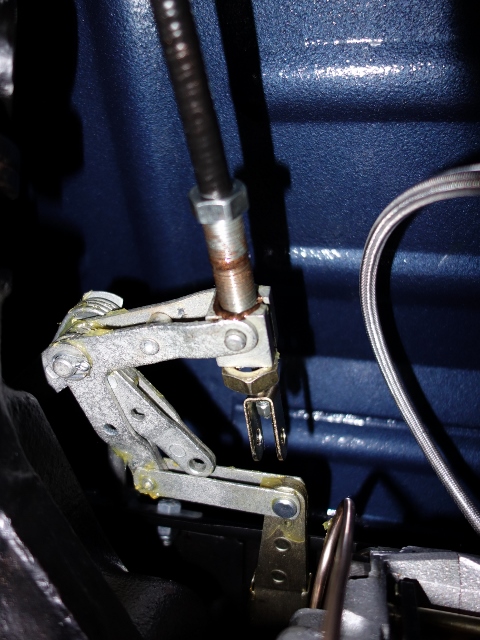
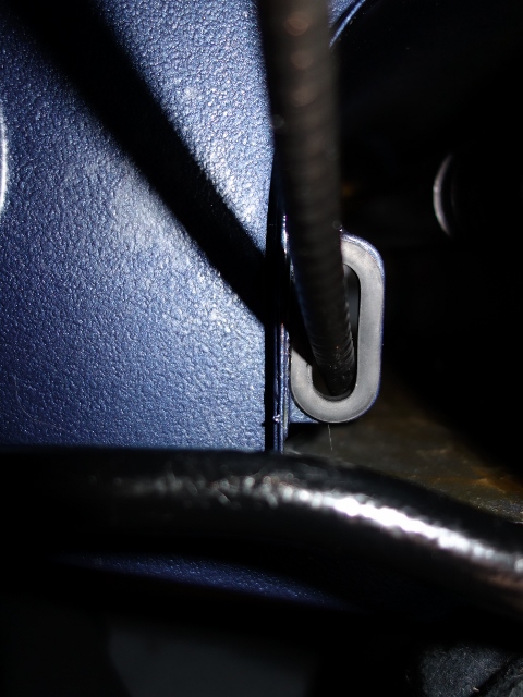
The revisiting of the handbrake was because I’d routed the cable incorrectly. It should pass through an eyelet on the inside of the transmission tunnel, with a rubber grommet protecting the cable. The cable was too stiff to re-route in situ by disconnecting the cable from the handbrake mechanism. So the entire cable had to be removed.
| Re-routing couldn’t be achieved by just disconnecting at compensator linkage | Correct routing of cable through grommet in transmission tunnel eyelet |
|---|---|
 |
 |
The final straw came when I found that the seat for one of the bleed valves had been machined too far. So the coned face at the end of the valve could never make contact with the seat, let alone form a seal. Longer valves are available … but not in the course thread used in the kit. There was no alternative – it had to be replaced.
I’m sure Stevsons would have rectified the problem but I now had the opportunity of fitting a better quality of kit. An order was placed and the Fosseway kit arrived the next day! The main difficulty was, with the IRS now in place, access was severely limited. The front pair of springs and dampers had to be removed to access the calipers.
| Forward rear springs removed for access | The Fosseway kit has better banjo attachments | Fosseway kit uses sprung bleed valves |
|---|---|---|
 |
 |
. I'd only come across the standard fixed valves before.") |
The Fosseway kit uses a banjo attachment at the calpiers which is a neater solution and much easier to fit, as it doesn’t require the flexible pipe to rotate when tightening it into the caliper. The other difference is the style of bleed valve used, sprung valves rather than standard solid valves. The sprung valves help with bleeding as the spring stops air entering the system between pumps of the brake pedal. In the end, replacing the remote bleed kit was easier than I had thought and only took an hour and a half.
Brake Bleeding Woes!
This was another task that proved far more troublesome than I had expected. Most methods of bleeding require the help of an assistant. The exception to this is vacuum pumps, such as the Mityvac, which can be operated single-handed. The vacuum is applied to the bleed valve to draw the fluid through the system so both the vacuum and bleed valve can be controlled from one location.

Mityvac vacuum bleeding tool
It was for this reason I purchased a Mityvac pump to replace my old Eezibleed tool. The Eezibleed pressurises the reservoir to push fluid through the system but still requires two people to operate. So doesn’t really offer anything over the traditional method of pumping the brake pedal.
The correct bleeding sequence according to the service manual is the near-side followed by the off-side, starting with the rears and finally moving to the front brakes. The reservoir bottles were filled, the RH reservoir feeding the front brakes and the LH reservoir the rears … let the bleeding begin!
After about 1/2 hour of trying with the Mityvac, absolutely nothing had come out of either of the rear valves. Time for plan B – the Eezibleed was rigged up to the reservoir. All this achieved was pressurising the bottle to what looked like bursting point and spraying fluid everywhere from around the cap. Thank goodness I’d gone for silicone fluid! Still nothing was coming out at the rear calipers.
Plan C! The traditional approach – the good old brake pedal and a patient helper! The resistance started to build after 20-30 pumps of the brake pedal. However this would dissipate after about 30 seconds. Frustratingly there was still no fluid coming from the rears. I suspect pumping the pedal was only pushing fluid into the front circuit and the resistance felt at the pedal was due to the air in the pipe being compressed. Once the pumping stopped the air pressure would force the fluid back into the reservoir.
Stumped, I decided to search the web to find out if there was a specific technique or trick that might help. At least I found out that I certainly wasn’t alone in having trouble bleeding the rear brakes, especially filling a dry system. One tip was to try bleeding the brakes with the engine running as the servo would be boosted by the vacuum. Still no joy!
Another suggestion was to first check the operation of the valve located in the output port of the servo cylinder. Once it had been confirmed fluid was coming out of the servo cylinder, simply loosen the rear bleed valves in turn, allowing the system to bleed naturally, under gravity. Note: the sprung valves need pressure to compress the spring to allow fluid out and so had to be removed for this method
The height of the reservoir above the remainder of the system provides a sufficient head of fluid to allow gravity to do the work for you. Whether the removal and inspection of the cylinder valve had fixed the restriction I’m not sure, but fluid was now coming out of both rear bleed valves.
Success was short lived …. when the brake pedal was depressed, fluid leaked out of the three way union mounted on the IRS cage. The problem was found to be the new flexible Goodridge brake pipe. Although sold as a direct replacement for the E-Type, the rear attachment was too short. It was a similar problem to the remote bleed kit – the attachment could never make contact with the seat and therefore create a seal.
| Short end of Goodridge brake hose was too short! | The additional mechanical brake light switch |
|---|---|
 |
 |
Several days and a new hose later, the system was finally bled. At the same time the last few braking tasks were completed: the brake pedal was much higher than the accelerator pedal and the mechanical brake light switch was fitted.
The height of the pedal is set by adjusting a ‘stop’ screw in the pedal housing, which was set to remove any free travel in the brake pedal. Unfortunately the clutch pedal is too high as well but this doesn’t have any adjustability. Other owners have had the same problem, caused by the push rod being 1/2″ too long on the replacement master cylinders. Another job to the list!

 was found to be a good 1/2\" longer than the JEC supplied cable. Fitting issues would have been made even worse as the bodged cable abutment had been moved rearward")
 was bodged with the cable abutment at the base moved rearward. The new ratchet come with the spacers welded") The knock-on effect is the distance between the outer cable abutment on the ratchet and that at the handbrake compensator mechanism on the IRS has been reduced by the same amount. Squeezing the outer cable into this shorter distance effectively reduces the overall inner cable length by 1″ – so a net shortening of approx. 1/2″.
The knock-on effect is the distance between the outer cable abutment on the ratchet and that at the handbrake compensator mechanism on the IRS has been reduced by the same amount. Squeezing the outer cable into this shorter distance effectively reduces the overall inner cable length by 1″ – so a net shortening of approx. 1/2″.  The fitting of the new ratchet was a simple task but the completion of the handbrake was foiled yet again. The bore of the outer cable abutment was 1/32″ smaller than the 3/8″ cable diameter. It has a slot machined into its circumference and is designed to allow a slight expansion, so I didn’t think anything was amiss.
  I needn’t have worried. As soon as the cable was twisted in the reverse direction, disaster struck …. one half of the abutment fitting snapped clean off.
  The main problem was mounting everything far enough forward so there was sufficient pressure on the striker to operate the switch.
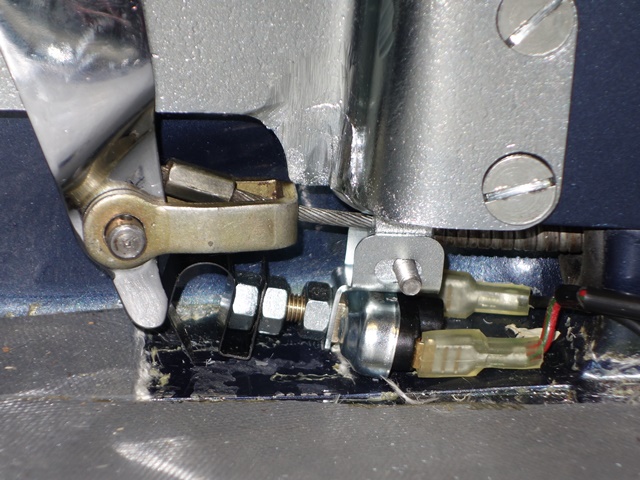 The only way I could get the switch’s plunger anywhere near to the ‘finger’ protrusion was to mount the switch to the bracket and then use two locking nuts to position the spring at the end of the switch – as shown in the photo.
 My handbrake had been hacked about at some time in the past. The bracket attachment has been cut off and welded further back.
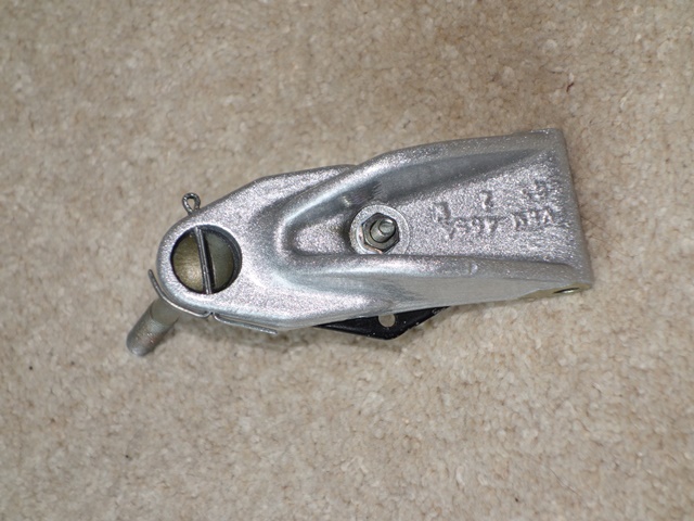
 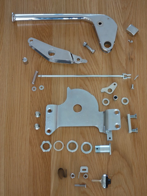 The handbrake had been sent off to ACF Howells for re-chroming as a complete unit. With hindsight it would probably have been better to dismantle it myself and just send them the pieces that needed re-chroming.


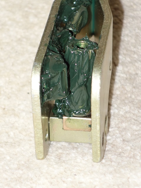
 Next the ratchet gear needs to be inserted into base of the handbrake arm followed by fitting the outer cable attachment bracket. Similar to the pawl, the ratchet gear uses two spacers to fill the internal space within the handbrake arm.
  The final piece in the puzzle was the fitting of the handbrake warning light switch. As mentioned, these parts were missing and so replacement parts were ordered from SNG Barratt.

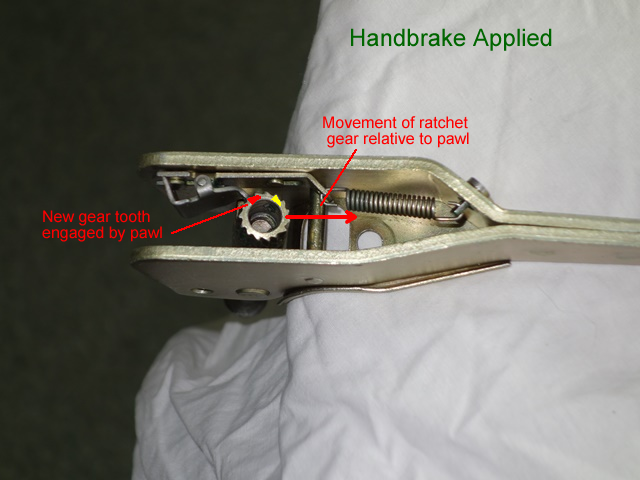
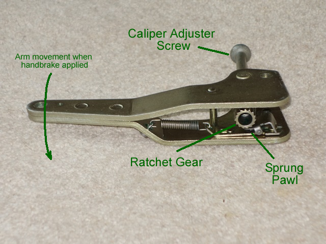 The handbrake system is self-adjusting using ratchet mechanisms to automatically compensate for the pad wear. The distance between the pad faces is determined by how far the caliper adjusting screw has been screwed into the ratchet gear.
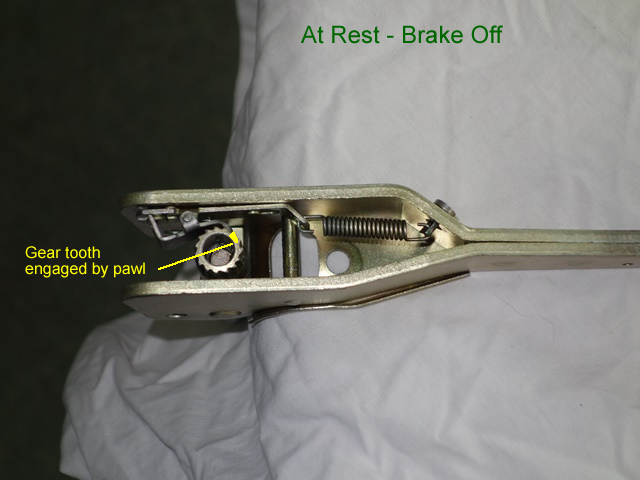
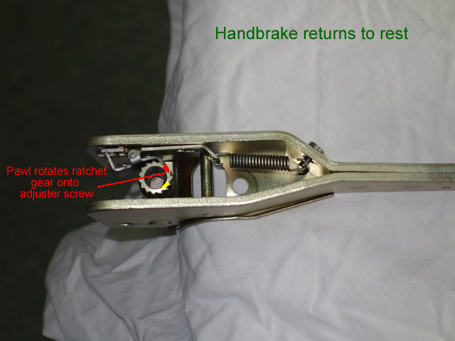
 I’m not sure if there is a correct or recommended order for rebuilding the handbrake mechanism. I started with the internal parts of the operating arm; the pawl slots onto protrusions on the arm which guide and limit its travel. A tensioning spring attaches to the pawl and the other end to an anchor pin pushed through the operating arm.
 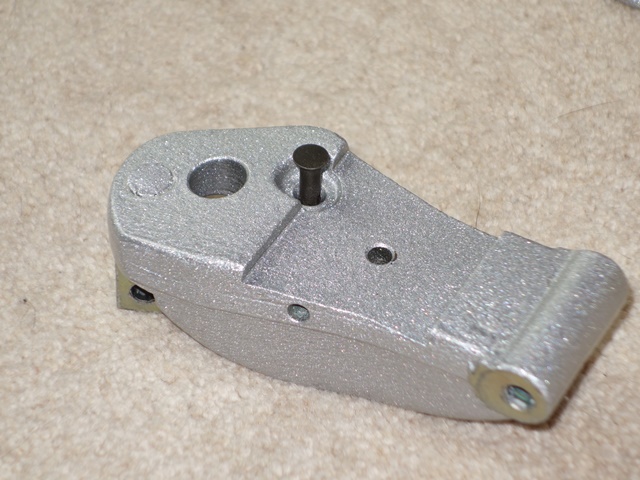 The operating arm could then be attached to the outer caliper arm. I found it easier to fit the operating arm return spring first which is attached at one end to an anchor pin pushed through the caliper arm and the other to a shaft in the operating arm.