Jul 152016
 

I’d been lucky to have an opportunity to drive an unmolested E-Type while on my recent travels (Sydney in an E-Type) and wanted to return the favour when the Christopher was next back in the UK. Not least because he would be able to give valuable feedback, good or bad, on how the two cars compare.

Crossing the Sydney bridge in an E Christopher’s original S2 FHC

I had experienced slight gear selection issues with mine when changing from 2nd to 3rd and from 3rd back down to 2nd – something I might cover in a future post. Although these were more due to being used to modern gearboxes and resolved by adopting a more sympathetic technique changing gears.

I had decided to keep reasonably close to the original spec. The most noticeable differences are the EDIS electronic ignition system and the Mangoletsi cable throttle linkage. The EDIS system hasn’t been properly mapped yet so the only real difference between our cars was the throttle linkage.

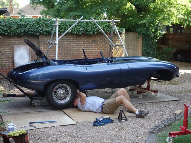
Christopher’s visit coincided with the car’s trip up to the trimmers to fit the hood. It had been up with Suffolk & Turley for a lot longer than expected and so the only opportunity for a drive was on the day he was returning to Australia.

This would have been fine had the MOT not expired while it was up at the trimmers. It had been there so long I hadn’t had an opportunity to organise a test since getting it back and now the speedo had seized. It might be possible to get away with a broken speedo on a modern car as the MOT tests are all static and the brakes tested on rollers.

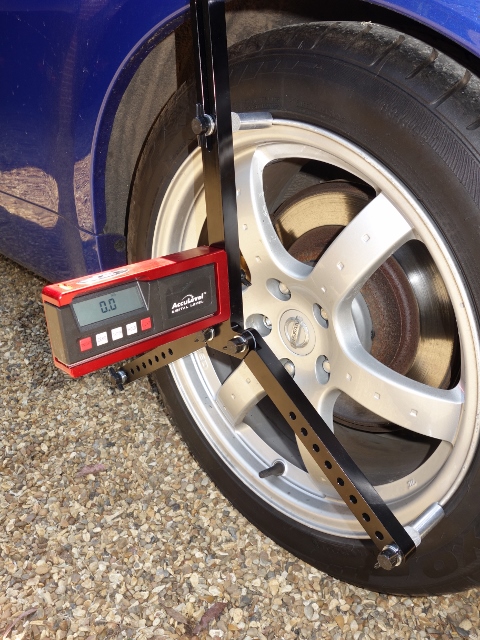
However due to the limited slip differential, the E-Type had to be tested out on the road whilst travelling at 20mph. Braking efficiency is measured using a calibrated decelerometer. Therefore it would be glaringly obvious that the speedo wasn’t working. So it was a race against time to get the car road legal before he left. No pressure then!

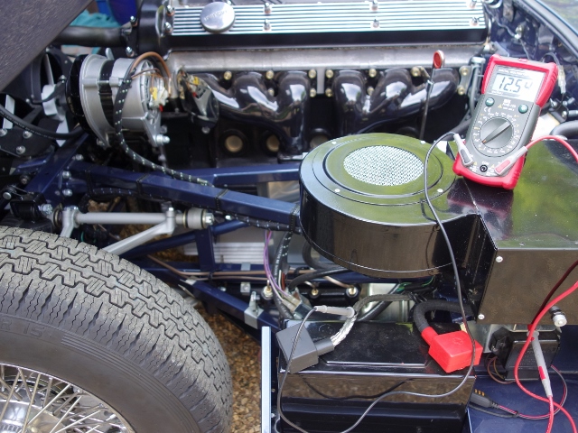
To make matter worse, I’d noticed the ignition warning light wasn’t going out indicating the battery wasn’t charging. I had a matter of days to resolve both issues and get the car through the MOT. Things weren’t looking too promising, especially when I contacted Speedograph Richfield as the speedo hadn’t turned up as expected. I had specifically asked for a 24 hour delivery but they had forgotten, sending it out 2nd class and without the ability to track it. Aaaaaah …. and relax!

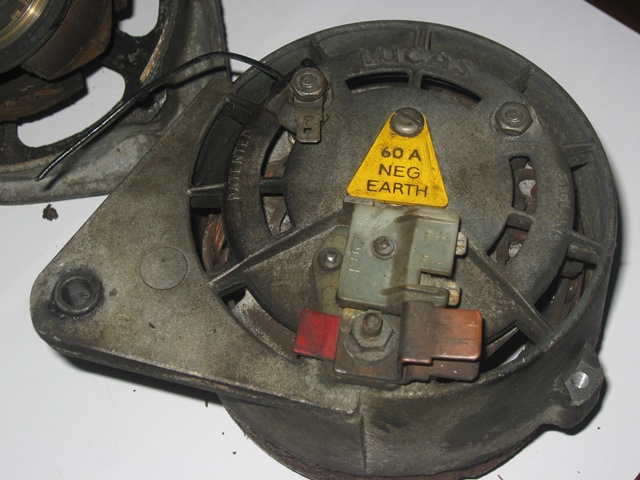
I was more concerned about the charging system since I had modified my alternator to a more modern design. This eliminates the 3AW and 6RA relays so the only two things that could be wrong were the 4TR voltage regulator or the alternator itself.

Modified alternator doesn’t need 3AW
and 6RA relays … less to go wrong!
Three additional diodes (trio) have been
added to self-energise the field coil

A failed 4TR regulator is fairly easy to diagnose. The unit is simply removed and a jumper lead used to link its connector’s F and – terminals together. Essentially this just puts the full battery voltage across the field winding and removes the feedback loop.


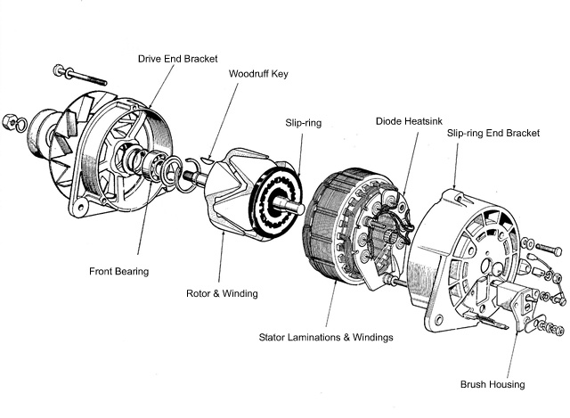
Alternator components

As the alternator starts spinning it’s output voltage increases. Without the feedback, the increased output increases the current in the field coil which, in turn, increases the alternator output voltage.

It would quickly reach a run away situation and burn out the alternator coil. Therefore, as soon as you’ve registered that the output voltage is increasing, you need to immediately switch off the engine.

I had pre-ordered another 4TR unit as a precaution but it wasn’t found to be faulty. It was the alternator. The modifications I’d made to the internal electrics and external wiring give it a ‘soft start’. The voltage across the field winding starts at approx. 1.5v rather than the full 12v battery voltage.

This is because the battery voltage is applied across the ignition warning light bulb (approx. 300 ohms) in series with the field winding (approx. 4 ohms). Hence the lions share of the voltage drop is across the bulb rather than the field winding.

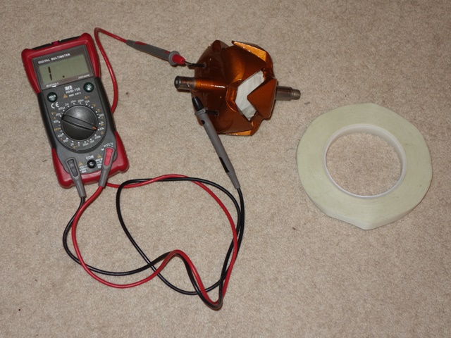
The measured voltage without the engine running was 2.74v which seemed a little high. I incorrectly deduced this would result in an increased current flowing in the field coil, which wouldn’t be a bad thing. Once the engine was started, this voltage only rose to 6.36v rather than the expected 14.4v.

The rotor field coil voltage was
higher than the expected 1.5v
With engine running, the field coil
voltage should rise to 14.4v

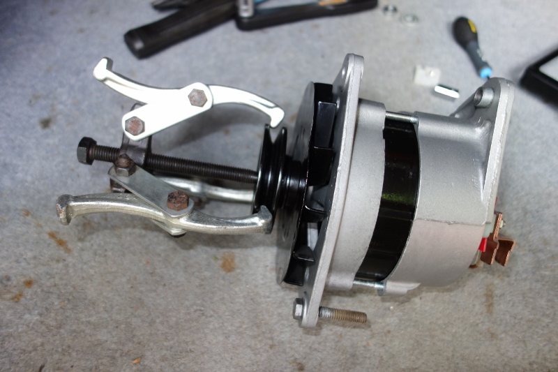
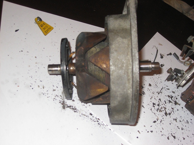
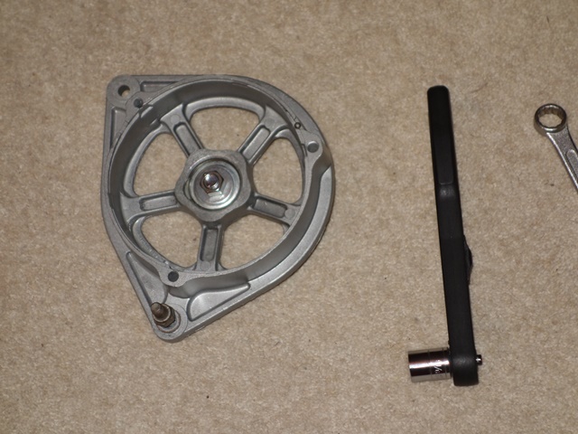
A reduced output typically points to failed diodes in the rectifying bridge. This became my main focus. The bridge needs to be removed from the 3-star stator windings in order to test the diodes. So the alternator had to be taken apart and it revealed some interesting problems.

The AL post’s insulating piece had disintegrated. I wasn’t able to source a new one and had to rebuild it as best I could, with araldite making up for the missing bits! Not ideal but it should do for now.

Pulling the pulley wheel AL post insulator had disintegrated Temporary fix – rebuilt with araldite

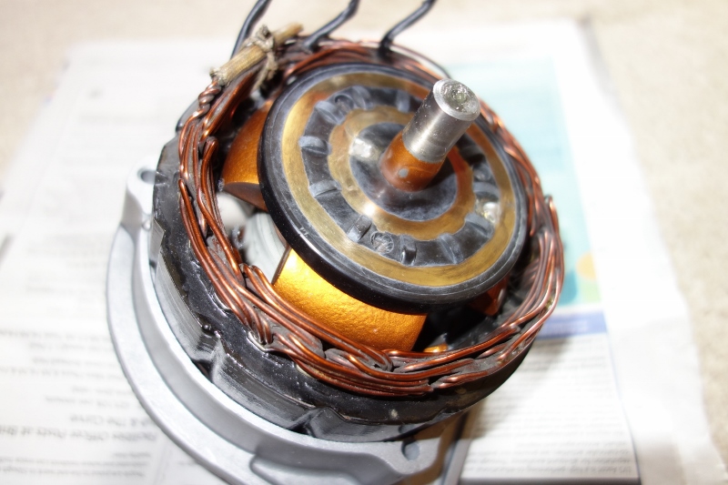
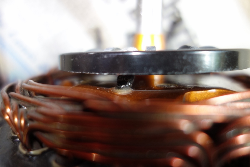
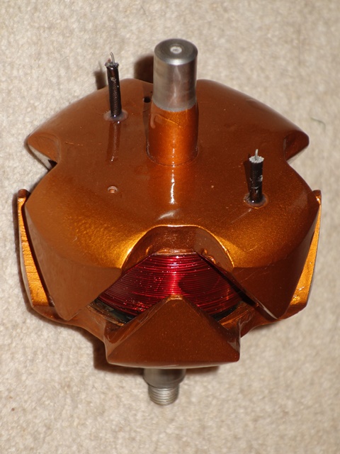
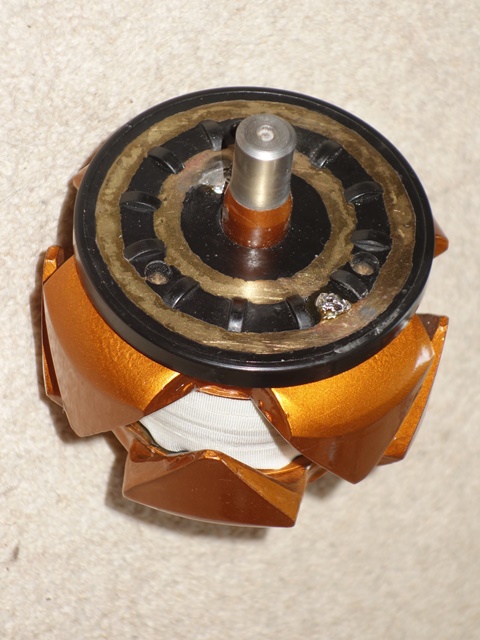
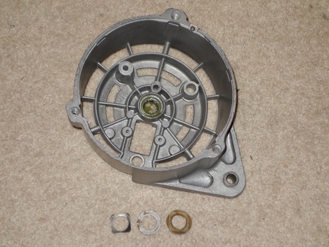
The original slip rings piece was found to be cracked so I had replaced it when the alternator was rebuilt. The replacement has raised sections between the rings but, as the brushes sit either side of them, I thought nothing of it.

These raised sections had been in contact with the brush holder and had worn a groove in the nylon housing. The slip rings looked clean enough but I gave them quick polish with wire wool.

Difference between slip rings Signs of rubbing on raised sections Groove worn in brush housing

My multimeter has a diode checking function so it was easy to check the diodes once the bridge had been removed. My suspicions were that one or more of the additional three diodes I’d added for the alternator modification had failed. They hadn’t and all the diodes were fine.

Removing the rectifying bridge Diodes can now be tested

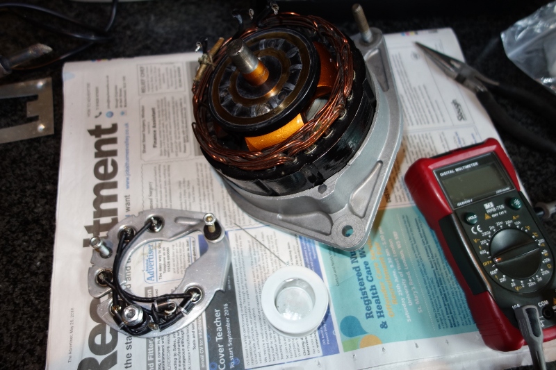
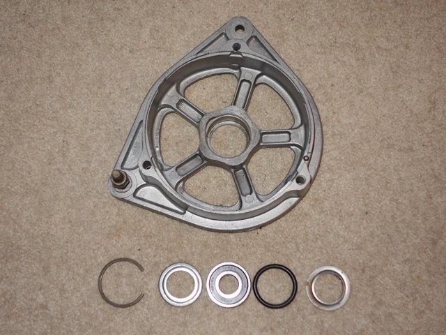
The other standard checks were made; the resistances of the rotor field and stator windings and the insulation between the rotor coil & rotor and the stator winding and stator laminations. All were fine … and I was stumped.

The alternator was rebuilt and put back on the car to test but there was no change. The ignition warning light stubbornly refusing to go out. I was getting fairly despondent. It was lunchtime, the alternator was in pieces on the bench yet again, there was no sign of the speedo, the car had no MOT and Christopher was due to turn up first thing the following morning!

For some reason I decided to measure the combined resistance of the rotor field winding and brushes. The rotor winding should be around 4 ohms. With the brushes included, I would have expected something in the order of 5 to 10 ohms (max). It varied between 30-40 ohms depending on the rotational positon of the rotor. This was way too high and would result in a significant reduction in the current in the rotor winding and therefore the output of the alternator.

Slip rings required light sanding Checking coil to rotor insulation

As a last resort and even though the slip rings had initially been cleaned with wire wool, their surfaces were sanded down with a fine wet and dry sandpaper. The combined resistance dropped to only 7 ohms. The alternator was quickly rebuilt and tested. Eureka – it was working!

I’m fairly sure the cause was due to the slip rings impacting the nylon brush housing. The resulting friction had melted the nylon to form the groove and some of the molten nylon had formed a glaze on the slip rings. The sharp points of the multimeter’s leads would penetrate the glaze to give a false impression of the resistance seen by the brushes.

I was expecting an initial voltage across the field winding of 1.5v rather than the measured at 2.74v. The higher voltage was due to a high combined resistance of the field coil and brushes compared with the 300 ohm bulb.


Refitting the alternator
… for the 4th time!

In total I had removed the alternator, taken it apart, tested each component, rebuilt it and retested it four times to get it working!

It was such a relief to get to the bottom of the problem and things started to look up when the postman arrived clutching the speedo. The garage kindly rescheduled things and its second MOT was passed late in the afternoon.

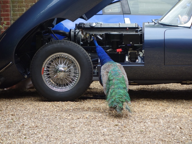
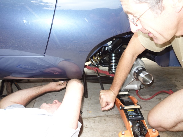
The following morning Christopher and I headed off for a drive and dropped in on his parents. His father had also had an E-Type years ago so it seemed fitting to vacate my seat so he could also go for a spin.

The feedback on how the two cars compared was positive too. The driving experience was very similar which was pleasing as there’s always a fear a restoration could change things for the worse.


Chris takes his father for a spin

One item that got the thumbs up was the PD Gough exhaust which has a lovely throaty roar from 2,500 rpm.

Something I can thank the administrator of the E-Type forum for as his advice was to stick to the standard cast manifolds, avoid the big bore systems and fit 1.75″ tubes with straight through silencers and straight through resonators.

Oct 162015
 

Default 4.2 ignition mapping

The EDIS Megajolt electronic ignition kit for the 4.2 engine was supplied with an ignition mapping that closely replicated the advance curves of the original Lucas 22D6 distributor.

The aim is to produce a mapping tailored to my actual engine by taking it to a professional outfit with a rolling road. Although I’ve been told it’s not for the faint-hearted. The engine is taken through its paces with sustained running all the way up to the red line!!

For now, I’ve followed a suggestion from the E-Type forum to load different mappings into the Megajolt controller to compare. A number of owners have produced maps for their engines and uploaded them to the forum for others to try. As the controller can store two different maps at any time, a discreet switch has been mounted in the glovebox to enable switching between two maps.


Checked into the Jaguar specialist
for further investigation

Although the final tuning and mapping is some way off as neither the garage that did the MOT nor Powerbell, a local independent Jaguar specialist, had been able to tune the carburettors to get the engine running smoothly. The latter suspected there might be either sticking valves or valve clearance issues which would require further investigation.

The engine had sat without being run for quite a long time since being reconditioned by VSE, which is far from ideal. The plan was to run the car for a while to see if the layup had resulted in a slightly sticking valve which might clear with use …. ever the optimist! Alas it didn’t! So the car was returned to Powerbell to get to the bottom of the rough running.

The first task was to perform a compression test and measure the valve clearances. The manual indicates that the expected compression pressures are 150psi for 8 to 1 compression ratio and 180psi for 9 to 1. The test showed mine were way off and in some cases almost non-existent:

Cylinder: 1 2 3 4 5 6
Pressure: 125 130 125 120 65! 10!!

The thicknesses of the valve adjusting pads under the tappets were miles out so everything was far too tight. The guys at Powerbell were shocked that they could be so far out in a newly reconditioned engine. Had I not decided to get it resolved now, they said the likelihood would have been burnt valves and a much bigger problem to resolve.

The compression test revealed very
low pressure in cylinders 5 & 6
Calculating the correct thickness
for the valve adjusting pads

I was relieved but at the same time not impressed with VSE who had rebuilt it. Unfortunately it’s way past the standard one year warranty they offer but I’ll not be using them again. It really shouldn’t be necessary to correct a simple measuring job that could have had expensive repercussions.

Removal of the camshafts to correct the valve clearances … on a newly reconditioned engine!

It was with some anticipation that I headed off to pick up the car when the call came to say it was ready. I really didn’t know what to expect but it had been transformed! It was now able to idle at the intended 700rpm, the rockiness had gone and it was running so smoothly.

They did recommend putting on another 1000-1500 miles on the clock, so the engine is properly run in, before mapping the ignition on rolling road.

 Posted by at 8:45 pm
Jun 162015
 

It feels as though the list of outstanding tasks is getting longer rather than shorter. So they have been prioritised into those required for the MOT and those that can wait. Due to the age of the car the MOT is essentially limited to checking the suspension, fuel/brake lines and lights. However, knowing the person doing the MOT, I’d asked them if they would cast a more critical eye over the whole car.

I’d been having trouble balancing the carbs and, although it’s not part of the MOT, I thought it best to have a second pair of eyes look over them. The front two cylinders are running too lean, even though all three carbs have been set to the standard reference point for tuning. So it will be tuned and the headlights aligned beforehand.

I also have concerns about the fuel flow. Last year the petrol tank had be put in-situ to just to start the engine for the first time. The tank was then removed to be painted and since then I noticed that the fuel flow seems to be rather low. Although I suspect I just hadn’t noticed the problem before.

Testing fuel flow from pump Comparing the fuel flows per minute:
250ml at front bulkhead in bottle,
2litres at rear bulkhead in jug

The measurements of the amount of fuel pumped in one minute was taken at the rear bulkhead union and then at the other end of the pipe at the union on the front bulkhead. Although it’s not really a valid test, as there wouldn’t be any back pressure at the rear union, it did provide a feel for the drop off in flow – 2 litres per minute measured at the rear bulkhead union and only 250ml per minute at the front bulkhead union.

Suspicion is that it may be due to an air-lock created in the pipes. However advice from the forum suggested that a pump in good working order would have more than enough ummph to purge any air locks. Some further checks will be done to get to the bottom of the problem.


Longacre Camber/Castor Tool

The intention was to set up the suspension geometry myself and so I’d purchased a Longacre electronic camber/castor tool and a Trackace tool for the wheel alignment. The camber/castor tool has three legs which rest against the wheel rim with an accurate inclinometer attached in the centre. However I wasn’t thinking things through and had completely overlooked needing clearance for the central spinners.

The prongs on the legs don’t have the reach so I’ll have to have some made up. Unfortunately the MOT centre no longer has accurate electronic measuring tools for suspension set up. This will have to wait until after the MOT.

For some reason one of the dash indicator tell-tale lights had stopped working and the fault traced to the switches in the indicator stalk. It was easier to take the whole steering column off and investigate further on the bench. A loose back-plate on the switch mechanism had allowed the indicator contact to move about and be bent out of shape. So it was easily rectified.

The clamping bolts on the upper and lower steering column’s UJs had been taken off to aid the removal of the upper column. However, I’d become side-tracked and had not refitted them before attempting to tick off another pre-MOT task … making sure the speedo drive was working.

Needless to say, as I was turning round, after completing a successful straight 40 yard speedo run up the drive, the lower column dropped out of its splines. All steering was lost, blocking a now busy communal drive!
Apart from being stupid, it was a rather timely reminder! The complete suspension parts list was used as a check sheet to ensure every suspension nut and bolt was revisited to make sure everything was correctly torqued.

Mudguards, shields and undertrays
The various mudguards, shields and undertrays aren’t strictly necessary for the MOT. However they were fitted, as the horn relay needs to be mounted on the LH mudguard. John Farrell had produced a good guide to the locations and orientations of the five different types of brackets:

Front frame bracket locations Five different bracket sizes

The first to be installed was the air in-take shield which is attached to bracket A at the top and B at the bottom. The leading face is also bolted directly to the frame. It’s worth noting that bracket E for the floor undertray needs to be put in place around the frame before the shield is attached. In fact it’s worth putting all the brackets in place before attaching any of the mudguards, shields and undertrays.

A & B brackets for air intake shield Bracket E for undertray is fitted
before in-take shield!

The bracket attachments to the frames are identical on both sides of the car, with the obvious exception of the air in-take shield. The torsion bar shields are attached by three brackets – the rear two have the tab with the bolt holes pointing upwards while the front one points downward. Note: the middle bracket on the LH frame is also used to secure the bottom of the exhaust heat shield.

Alternate rear torsion bar shield
& undertray brackets
Shield bracket also attaches bottom
edge of exhaust heat shield
Front torsion bar bracket (L)
and mudguard bracket (R)

The two floor undertrays are simply bolted in place. Although the right hand undertray has a cut out with a separate cover to provide access to the oil filter.

Left hand undertray Right hand undertray,
without oil filter access panel

There wasn’t any point in completing the fitting the mudguards because they will have to be removed to provide access to set the camber and castor. So at this stage they were only bolted to the sill end panel and attached at the front to a side frame bracket. At least this allowed the horn relay to secured for the MOT. Normally the alternator and aircon (when fitted) relays would also be attached to the LH mudguard, but by modifying the alternator it no longer requires a relay.

LH mudguard temporarily in place just for the MOT Location of horn relay. Alternator relay isn’t needed

Air Filter
I was regretting not trial fitting the air filter earlier. The new fuel pipe I’d made protruded too far from the face of the toe box, hitting the air filter. Fortunately it was possible to remove a short length from the filter end which resolved the fitting problem but re-introduced all the air bubbles causing the air locks.

It took a while to work out the best method of fitting the air filter element, canister lid and air plenum. Once the canister lid and rubber grommet are in place, there wasn’t sufficient access to pull the grommet up around the lip of the plenum chamber. Eventually I found the best solution was to connect these components off the car and then fit and remove as a single unit.

Filter canister was hitting the fuel pipe Adjusted fuel pipe now narrowly misses it Fitting canister lid first didn’t work

Alternator testing
Another task was to ensure the alternator was charging properly when the engine was running at higher revs. The outcome wasn’t as I’d hoped – it wasn’t charging at all, measuring only 12.5 volts! The converted alternator is now self-energising – the AL terminal, normally used for monitoring the alternator output via the ignition warning light, now provides a DC supply to power the field coil. Finding earth via the field coil through the 4TR voltage regulator.


Testing the alternator

The AL terminal was reading zero voltages at idle rather than the expected 14.3 volts! The voltage regulator controls the alternators output to avoid ‘run-away’ where its output would continue increasing until it burnt out the various internal components and/or windings. Increasing the voltage across the field coil increases the alternator output voltage, which in turn increases the field coil voltage.

The 4TR regulator acts as a fast-acting on/off switch. When the output of the alternator increases above a determined voltage (around 14.6v), the regulator switches off the current flowing in the field coil and therefore the alternator voltage drops. Once it has dropped sufficiently, it switches the current in the field coil back on and the alternator output starts to increase, until the cycle repeats.


A passing peacock offered
no helpful advice!!

Suspicion fell naturally on my modifications to the alternator and also the 4TR regulator, which are known to be fragile. A faulty voltage regulator can easily be identified by removing it and using a jumper lead to connect the F and ‘-‘ leads in its connector.

If it is faulty, starting the engine will cause it to start charging (indicated by the alternator output voltage or the battery gauge rising above the battery’s normal 12.3-4 volts) If so, the engine should be switched off immediately and the 4TR unit replaced. It was a great relief to find it was the 4TR unit that was at fault and not my handiwork! A replacement was ordered which confirmed the diagnosis and it is now working as expected.

Crossing fingers
I didn’t want to drill holes in the bodywork for side mirrors and so some clamp on mirrors have been attached to the window frames. That just about completed all the pre-MOT jobs.

Clamp on side mirrors fitted After all this time, it’s finally ready for the MOT!!

For the first time in several decades, 1R1421 hit the road …… on it’s way to the MOT centre! …. fingers firmly crossed!!

Nov 132014
 

Time pressures delayed the full electrical shakedown testing until after the engine was up and running. Power is only required to the ignition and fuel pump circuits to start the engine so all the other fuses were removed. Having said that, I did end up fitting the fuse for the instrument voltage regulator in order to obtain oil pressure and temperature readings while the engine was running.

The other fuses were now fitted in turn, stopping to test each of the components they fed, before moving on to the next fuse. The resulting snagging list was encouragingly minor:

  • The main beam can’t be flashed from the indicator stalk
  • The original hazard flashing unit is on the blink!
  • The brake fluid warning light isn’t coming on
  • The wiring to the rear brake and sidelights have been crossed over
  • One of the cooling fans is a little noisy and spins the wrong way!
  • The heater fan is making contact with the housing
  • Neither the washer or wipers work
  • Only one horn worked

Overall I was quite pleased with that for a first test. Especially as it was the first time the cooling fans and wiper motor had been tested since I rebuilt them and the washer, wiper, brake fluid warning light and horn were all simply missing earth connections. So easily solved.

Indicators and hazard lights
There was a fair amount of head scratching when wiring up the hazard warning light switch. The part number identified it as a hazard switch from an XJ6 and its pin connections conflicted with those in the Illustrated Parts Manual!

Hazard wiring diagram Hazard switch wiring

So I attempted to go back to first principles (or my understanding of them!) to work out the correct wiring. The one thing that was puzzling me was why separate indicator and hazard flasher units were used. They are essentially performing the same role – converting a constant DC supply into a square wave, with a suitable duty cycle to provide the correct flash duration and frequency.

The light bulb moment came when reading the requirements to pass an MOT. The hazard lights must be able to operate without a key in the ignition while the indicators are only powered when the ignition switch is on. The other difference is the power rating as the hazard unit needs to draw more current drive both sets of indicator lights at the same time.

The duty cycle of the unit is achieved by a bimetallic strip which expands and contracts depending on whether current is flowing. When the indicators are on, the current generates heat in the two metals, which expand at different rates. This causes the strip to move away from its contact and break the circuit. Without a current, the strip rapidly cools and the circuit is re-established allowing current to flow once more and the process to repeat.

Therefore the flashing frequency or ‘duty cycle’ is directly related to the rate of expansion/contraction of the bimetallic strip, which is a function of the current flowing. This is why modern LED indicator bulbs often do not work on classic cars as they draw far less current and therefore may not generate sufficient heat to switch the traditional units. Modern transistor based units are available to overcome the problem.

Therefore the switch needed to have the following connections:

Hazard switch in OFF position

  • Indicator flashing unit is introduced into the circuit (the two green wires are connected)
  • Hazard flashing unit is cut out of circuit (connections between the LGN, GR & GW wires are broken)
  • The indicators can then be operated via the switches built into the indicator stalk

Hazard switch in ON position

  • Indicator flashing unit is cut out of circuit (by removing power to its green wire)
  • Hazard flashing unit is introduced (by connecting its LGN output to both the GR & GW indicator feeds)

The only problem was the random frequency of the hazard flashing which was easily solved by fitting a new flasher unit.

Cooling Fans
The S2 cars have an otter switch to turn on the cooling fans at its rated temperature and requires a special connector, which has been on back order for ages. A spare dash switch was rigged up in its place so the fans could be switched on and off at will, which would be useful when testing and tuning the engine. The first fan spun up and ran smoothly and quietly, which was very pleasing, as they hadn’t been bench tested after their refurbishment.

However the operation of the second fan was noisier because the blade was not quite square on the armature shaft, causing vibrations. Removing it was a fiddly process with the engine bay completed so I was cursing not having bench tested it!


But more importantly, the motor was rotating the wrong way, pushing air forward towards the radiator rather than drawing air through it. Its effect would be worse than having no fan at all. When travelling at speed there would be a natural flow of air through the radiator. Having a fan blow against this flow would reduce the cooling ability.

It is rather odd because reversing the supply polarity of series wound DC motors (and indeed shunt wound motors) does not reverse the direction of rotation. The only way to rectify this would be to reverse the connections on either the field or the rotor windings (but not both!).

The rotating force (torque) on the armature shaft is the result of the interaction of the magnetic fields of the armature and the field winding – opposite poles attract, like poles repel. The directions of these magnetic fields are dependant on the direction of the current following through them.

Therefore changing the polarity of the power supply does not reverse the direction of rotation because both the field and armature currents will be reversed and therefore both magnetic fields. A double negative if you like, that cancels each other out!

The only practical option for these Lucas motors was to reverse the field winding, which was a very simple job.

Field wires just needed swapping All sorted – an easy soldering job

The fan now rotates in the correct direction to draw air rearward through the radiator. The fan was also re-seated to stop the fan vibrating so much.

I was trying to fathom an explanation as to why the motors were rotating the wrong way and then recalled that I had difficulty dismantling the two motors I’d acquired many moons ago, at the start of 2012. They were of the same design but had the fans mounted the wrong way round.

The person had indicated they were selling them as they had upgraded to modern fan units. However I suspect they had sourced motors from a different vehicle and noticed they were turning the wrong way. They had then mistakenly concluded mounting the fans the wrong way round would rectify the situation, rather than just improve their efficiency in making things worse!!

Wiper motor & Intermittent module


Intermittent control above
brake warning light

I’d decided to fit the Hella intermitted wiper module that other E-Type forum members had advocated. It works independently from the two speed wiper switch on the dash and the modification is reasonably discreet and reversible. The intermittent control uses the hole in the dash for the rear window heater on the FHC, which is blanked off on the OTS cars.

Like the hazard warning switch, the part number on the wiper motor switch also suggested it had originally come from an XJ6. The problem was the connected terminals were different to the correct switch (OFF 5-7, Normal 4-5, Fast 2-4) and so it was another case of trying to work out how it should be wired.

The combination of common sense and trial and error eventually produce the correct operation, which differed from the wiring suggested by the forum post. I’ve wired intermittent module into the ULG feed rather than the suggested YLG wire, which is for operating the motor at high speed.

At the same time, I also decided to add a jumper lead (with an inline diode) from the washer switch to the slow speed supply to the motor. Therefore the wipers now operate automatically while the washer switch is pressed. The diode is needed to stop it working in reverse, with the washer operating when the wipers are switched on!

Heater Motor
A complete new heater unit had to be fitted as the original had largely rusted away. The resistor, providing the dual speed operation, is riveted to the base plate of the heater motor. I’d foolishly assumed the new units would be supplied complete with the resistor already attached – dream on!

The resistor is sold separately and, due to the lack of clearance, requires the base plate to be removed from the motor in order to fix it. The wires are then soldered to the resistor rather than via spade connectors. As a result, the loom has bullet connectors built in, approx 6″ from the end of the wires, to allow the motor to be separated from the loom if it needs to be removed for servicing.

Resistor provides 2-speed operation Loom wires are soldered in place Fitting was tricky due to
the engine frame

However the looms didn’t come with the rather crucial two wires needed from the resistor to the motor terminals! The other issue came trying to re-fit the motor to the heater housing which had already been attached to the bulkhead. Removing it wouldn’t be an easy option as the cooling system had now been filled.

The reason the motor and fan cage couldn’t be fitted onto the housing was the base plate fouled on the engine frame. It was necessary to detach the fan cage from the motor by undoing the clamping grub screw. This allowed the cage to be fed up into the housing and then reconnected to the motor once the motor was clear of the engine frame.

The fan just had to be re-attached ever so slightly nearer the motor to cure the fouling problem found during the initial shakedown tests.

Alternator testing
The electrical component that I’d been putting off testing was the re-wired alternator. The modifications to the alternator were more far reaching than any of the other electrical work and so there was more scope for things to go wrong. Once all the other electrical issues had been resolved, I fitted the alternator belt and prepared to start the engine. Would it work or would it blow any of the other components?

Unfortunately I didn’t have a suitable ammeter to measure the theoretical maximum output of approx 60 Amps and so my testing was limited to measuring the voltage at the battery terminals with a multi-meter:

  • With the engine off, the terminal voltage should be approx 12.7v
  • When running at idle, the alternator should raise the terminal voltage to around 13.9v-14.3v
  • The terminal voltage should reach between 14.3-14.6v running at 2500 rpm

In theory if the alternator output drops from the last two levels then it points to the failure of one or more of the rectifying diodes. If it rises above 14.8v, then the 4TR voltage regulator unit is not limiting the maximum voltage and needs to be replaced to avoid overcharging the battery. However I also have to consider that any lack of output could also be due to the additional diodes introduced to self-energise the field winding.

It was a welcome anti-climax that the initial test appeared to be successful. Although I’ll need to do further checks to ensure it’s charging when the car is run for a longer period.

Nov 082013
 

The ‘refresh’ of the alternator turned into a full rebuild because the rotor’s slip ring needed to be replaced, as it was heavily grooved, and the main rotor bearing had seized. In fact, the slip ring was found to be cracked on the underside once it had been removed. Fortunately all the components needed for a rebuild are still readily available.

The wiring diagram for the Rootes Parts Lucas 11AC alternator conversionAs previously mentioned, the Rootes Parts website covers the conversion of the internal electrics to a more modern, self-energising design.

The revised electronics energises the rotor field winding from the alternator’s output, rather than directly from the battery. This produces what Rootes term a ‘soft start’. When the car is started, the output from the alternator is zero, so a much reduced current flows through the field winding as it is wired in series with the more resistive Ignition Warning Light bulb.

The initial current in the field coil is approximately 10% of the normal operating current. However as the alternator output increases up to a typical 14.3v to charge the battery, the voltage either side of the warning light becomes equal, effectively removing it from the circuit energising the field winding. As there’s no voltage drop across the warning light, it goes out and the field winding is now powered directly from the 14.3v alternator output.

Being self energising also has the added benefit that if the belt fails, the alternator output would fall to zero and the field winding current reduces back to 10% of the normal operating current. Thus avoiding the field winding being burnt out.

The slip ring plate needed to be replaced but first needed the field wire connections un-soldered
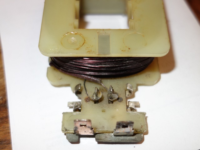
Three screws fix the split ring plate to the rotor. Once removed, the plate can be pulled away from the rotor to reveal the ends of the rotor field winding, which pass through the rear of the slip ring plate and are then soldered at the front to the brass slip rings.

It took a high output soldering iron to melt the solder joints, probably due to the age of the solder, enabling the slip ring plate to be removed.

The rotor’s field winding wire is insulated by an enamel coating and then covered by a fibreglass tape so these were protected by masking tape before the rotor was bead blasted, in preparation for painting. The rotor was painted in numerous coats of Burnt Copper and then Clear VHT Engine Enamel paint. VHT paint was chosen due to the high operating temperatures reached and the proximity of the alternator to the exhaust manifolds.

Painted in Burnt copper VHT Curing in the oven Winding re-lacquered

The rotor was painted with Burnt Copper VHT Engine Enamel paint and then a VHT clear coat

The VHT paint needed to be cured in the oven to obtain its full protective properties

The field winding was re-enamelled and the ends re-sleeved to ensure the winding does not short with the rotor body

Once the paint had dried, it was cured in the oven at around 100 degrees Celsius for about 45 minutes ….. and, rather sheepishly, the oven then left for a day or two until the aroma had gone! The fibreglass insulation sheaths covering the ends of the field winding had deteriorated and eventually broken free with all the disruption getting the slip ring plate off.

I found an electronics supplier, Brocott UK, who supply the 2mm fibreglass sheathing as well as bottles of motor winding enamel and new fibreglass tape. After the old tape was removed and the winding cleaned up, it was re-coated with a generous coating of enamel. The new sheathing had to be held in place by a small amount of Araldite were it enters the rotor as I needed to ensure the field windings couldn’t short against the rotor body.

The field winding was re-taped which was a fairly fiddly job, as the 8 prongs of the rotor get in the way. I suspect the winding was originally wound and taped before the two halves of the rotor were fitted together. Before progressing any further, two important tests were made; i) the winding resistance and ii) confirming the field winding wasn’t shorting with the rotor. The winding resistance was 4.2 ohms which is slightly above the recommended upper limit of 4 ohms but I’m happy to leave as is.

Checking the winding wasn’t shorting New slip ring soldered and fitted

A multimeter confirmed the field winding has not shorted with the rotor body. The field winding resistance was also measured at 4.2 ohms

The field winding was soldered to the new slip ring plate and the field winding covered with fresh glassfibre tape

Attention now turned to the fitting of the main rotor bearing. The original had seized and so a replacement bearing kit was ordered. The new bearings are sealed for life units which have a slightly lower maximum RPM. However I was assured they would be fine unless driving at full RPM for prolonged periods.

The outer cover plate and then the rubber ‘O’ ring are placed in the front alternator housing before the bearing is tapped into place. Finally the rear cover plate is inserted and the whole ensemble retained in place by a circlip. I couldn’t compress the parts sufficiently to fit the circlip, due to the thickness of the new rubber ‘O’ ring, and had to resort to clamping them between two suitably sized washers using a bolt. With the bearing installed, the rotor was tapped into the bearing with a nylon hammer.

Parts of new bearing kit Compressing the ‘O’ ring Rotor press fitted into bearing

New bearing kits are available. A rubber 'O' ring sits between the front cover and the drive end housing. The rear cover is secured by a circlip

It was necessary to compress the 'O' ring in order to fit the circlip at the rear

Once fitted the rotor was gently tapped into place with a nylon mallet

It was only at this point that I found a spacer that is clamped between the inner bearing race and the fan & pulley did not fit. The inner diameter of the new bearing cover was too small to enable the spacer to be fitted. So the whole bearing had to be removed and re-fitted using the original outer cover!

Alternator’s internal electronics
The stator's three field coils attached the stator to the rectifying diode housing
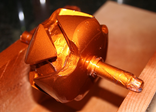
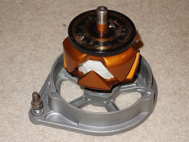
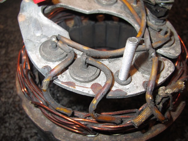
The rectifying diode housing and attached stator were removed from the rear housing by undoing the external nuts on the three terminal posts. Once again I had great trouble de-soldering the joints, this time connecting the stator windings to the diode housing.

The problem is that typical soldering irons, used in electronics, don’t have sufficient output to melt the solder. This is mainly because the relatively large gauged wire used dissipates more heat than the soldering iron can deliver and the diode housing is designed to act as a heatsink.

So I’m now the proud owner of 4 soldering irons, with increasingly higher output ratings! The highest being an 80W iron normally used for soldering stained glass window frames – it was ideal!

The Lucas 11AC alternators use a three-phase bridge rectifier, containing two sets of three diodes, to convert the AC output from each of the three stator windings into DC. Essentially the output of this type of rectifier is close to a DC supply as it is the sum of the positive components of the three AC voltages, which are 120 degrees out of phase from each other.

The conversion involves adding a further set of three diodes to provide an additional DC output to power the rotor field winding. The self-energising alternator no longer requires a 3AW relay so the AL terminal can be re-used for the secondary DC output.

Each terminal post has a variety of insulations and metal fittings – their fitting order was carefully noted as each part was removed to ensure they were correctly refitted during the rebuild, as shown in the photo below.

Notes taken during disassembly Parts assembled for the conversion

Details notes were taken during the dismantling to avoid problems during the rebuild

The numerous parts needed to rebuild the rectifying diode housing, including the additional diodes for the feed to power the field winding

The main points to note are the B+ and AL terminal posts must not short with each other or the alternator casing. With this in mind, the order and purpose of insulators becomes more obvious. The diode housing consists of two halves into each is pressed a set of three diodes. The two halves also act as part of the circuitry as well as a heatsink.

The left hand side is connected directly to the alternator housing via the Earth terminal and provides the common anode connection for the three (negative) diodes. Similarly the right hand side provides the common cathode connection for the three (positive) diodes, which is the B+ output.

The original AL terminal is connected to the wire connecting a pair of the rectifying diodes. This will be replaced during the conversion so the AL terminal is then connected to the output of the three new diodes.

Although the six button diodes look identical, the outer casing acts as the anode for the three inserted into the left hand heatsink (their cathodes being wired to the stator coils) while it acts as the cathode for the other three. Therefore it is essential to ensure they are installed into the correct side of the diode housing. Fortunately most multimeters have a diode test function so it’s easy to check which is which.

The same 2mm glassfibre sheathing for the rotor winding was used to insulate the 16swg copper wire connecting pairs of diodes on each half of the diode housing. Again, the 80w iron made the soldering a doddle. The next step was to install the additional three 6 amp diodes to provide the output for the field winding.

Their anodes are soldered to the anode posts of the positive diodes, delivering the B+ output, and their cathodes are all connected to the AL post. I crimped and then soldered the cathode wires into a 3/16″ eyelet terminal which fits neatly onto the AL post.

Wiring of the standard rectifying diodes Additional diodes to power field winding

There’s not a lot of room between the rectifying diode housing and the rear alternator body so insulation was added to the leads of the additional diodes. Several trial fittings were made to ensure the diode housing did not foul within the alternator body, before finally soldering the diodes in place.

In the meantime the resistance of the stator coils had been checked to ensure all was well before the stator was cleaned up – wire brushing to remove all the rust and then repainting. The stator was then reattached to the diode housing by soldering the coil field wires.

The bearing kit came with both front and rear bearing so the latter was pressed into place and the bearing completed by fitting a felt washer followed by a metal washer and finally a square, spring washer. The corners of the spring washer lock against the alternator housing and hold the other washers in place.

Rear bearing components Housing alignment markings

Two things I wasn’t sure about was whether to soak the felt washers in oil and what grease to use for the bearing. In the end I soaked the washer and opted for a polyurea grease. Hopefully it should be ok! The stator and diode housing could then be refitted to the rear alternator body, taking care to add the various insulating washers.

New slip ring brushes were fitted before reuniting the two halves of the alternator. The two alloy halves have a small dimple marking which both need to be aligned with the narrower and deeper groove in the stator.

The rebuild was completed by fitting the spacer on the rotor shaft followed by the Woodruff key, the cooling fan and finally the pulley.

Electrical terminals at rear Front & rear halves reunited

The only decision left is whether to get the alternator professionally tested off the car or wait until the engine is running …..

Installing the IRS – it’s only a matter of 8 bolts …

 Rear Suspension  Comments Off on Installing the IRS – it’s only a matter of 8 bolts …
Aug 232013
 

I had been waiting on the completion of the front suspension components so that everything would be in place to transform it from a bodyshell to a rolling chassis; installing the front & rear suspension as well as the engine over a weekend. I even dared think we might be able to have a stab at starting the engine.

I had read and re-read all the available manuals a number of times to produce a detailed list of tasks that needed to be completed prior to and over the installation weekend.

Adapting the IRS trolley to fit under the IRS cage and raising the platform height
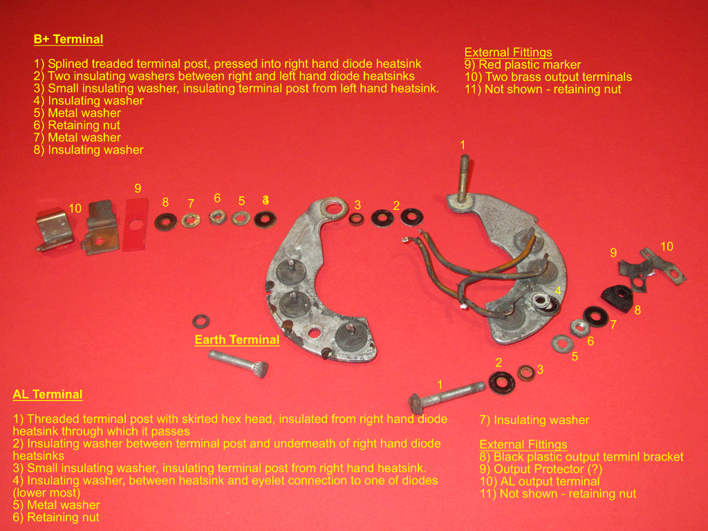
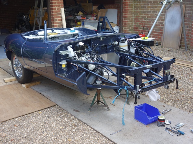
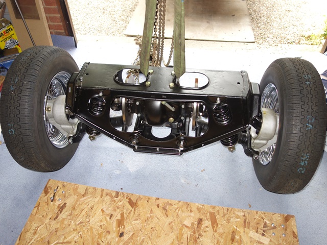
The first task was to adapt the original IRS trolley I’d made; reducing its footprint to a little larger than the base plate of the IRS cage so it wouldn’t get in the way during installation, giving it sufficient ground clearance to allow the trolley jack to be inserted underneath and raising the height of the cage so the wheels could be put on while on the trolley.

I’m not sure about the need for the latter but it made sense at the time! The aim was to be able to lift the IRS and trolley to meet the chassis.

A number of other tasks before the weekend involved the IRS unit which had been sat on its trolley for over a year. Even though it was dry stored, the caliper plating had already deteriorated in this time. These were removed and painted in a tough, silver caliper paint and a remote bleed kit fitted.

The IRS cage had also picked up a variety of scuff marks when it had been delivered and moved around. It was therefore given three coats of 2 pack black paint and two clear satin coats. I didn’t have the luxury of a spray booth so boards and boxes were used in an attempt to keep bugs and leaves off while it dried.

Masking up on the smaller trolley Attempt to keep bugs off Re-painted – not much different!

The planning was finally over and the installation weekend had arrived. Much needed help was drafted in, John had been granted a pass for the dereliction of parental duties who then managed to persuade Martin to travel down to complete the line up. Both had ample engineering knowledge to complement my tea making skills!

Four Metalastik mounts connect the corners of the rear suspension cage to the chassis. Restricted access during the fitting the IRS unit is overcome by pre-fitting the rear mounts to the chassis and the front mounts to the IRS cage. ‘All’ that remained was to raise the IRS to the chassis and fit the remaining 8 bolts. I had foolishly assumed this would take an hour or so at most.

John and Martin assessing how to overcome the fitting problem None of the bolt holes were close to lining up. Hmmm. The IRS was removed and all the mounts then fitted to the cage in order to compare the centre to centre distances. The C2C distance between the mount holes was 6mm greater than the chassis holes.

As they are attached at an angle of 45 degrees, this would need each rubber mount to compress by √2 x 3mm to obtain hole alignment. So they became the prime suspect in the fitting problems.

A few tests of a mount in a vice suggested that it might be possible to achieve the necessary compression in the rubber section but exactly how was still to be determined. So the decision was made to continue rather than abandon the installation weekend.

The front of the chassis was raised in relation to the rear in an attempt to use the weight of the car to compress the rubber in the rear mounts. It still wasn’t sufficient – we needed more weight in the rear. A few moments later, Martin and I were standing in the boot while John assessed whether this had achieved anything other than a comical moment.

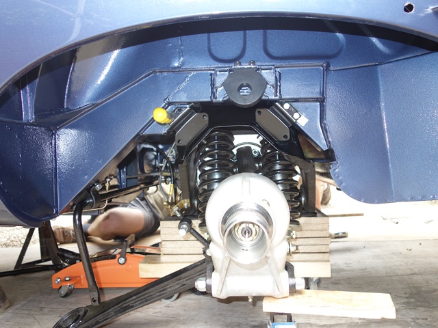
Eventually each bolt was persuaded one by one until the IRS had been fitted. A successful method was to insert a screwdriver into the second bolt hole to lever the first bolt hole into alignment and then tap the bolt home. I later found out that such fitting issues were far from uncommon.

We just needed to connect the radius arms to complete the job. Unsurprisingly they were also a country mile off fitting on to the cups on the chassis and were also twisted in relation to the cups because there was no load on the suspension. The solution was a three man job. John applied a tourniquet to draw the IRS cage forward so the radius arm and cup aligned. At the same time I rotated a G-clamp attached to the radius arm while Martin fitted the retaining bolt.

Just the radius arms to go Applying a tourniquet to pull into alignment G-clamp was also needed

Almost the entire day had been taken up with fitting the rear suspension but at least we had the satisfaction of finally lowering the car onto two of its new 5″ wheels. I had been wildly optimistic on what could be done in a day but nevertheless was pleased with what had been achieved.


The front suspension and engine would have to wait for another day ….

Aug 212013
 

This is more of a retrospective post as the IRS rebuild was originally completed in line with the indicative chassis completion date of May 2011 given by Hutsons. I had stripped and painted all the components but needed a specialist to address the differential. By chance I decided to get it done by Alan Slawson from AJS Engineering.

I wasn’t aware at the time but one the two Jaguar World books that persuaded me to buy the E-Type included a section covering the IRS rebuild. Alan was the person they entrusted to do their rebuild so it seemed fitting he would also be doing mine.

When I arranged to pick up the diff I asked him if he would be prepared to do the full IRS rebuild. Although he was semi-retired he agreed, as long as I wasn’t in a rush for it. The aim was to free me up to tackle the 101 other things needed to be ready for the return of the chassis.

In the end Hutsons took much longer than hoped due to a very healthy backlog of restorations. It was shame really as I’d have preferred to rebuild it myself and would have had ample time to do so. Several months after dropping the parts off, Alan had completed the IRS and even drove over from Essex to drop it off. At his suggestion Gaz adjustable shock absorbers were fitted in preference to the Koni Classic ones I’d supplied.

Also at his recommendation was to rotate the larger radius arm bush through 90 degrees. The rubber section has two elongated holes which are normally orientated so they are front and rear. Rotating the bushes so the holes are at the sides marginally increases the fore and aft stiffness, which is in the direction of forces through the radius arm. I subsequently found out that this is common practice.

The IRS unit is quite a heavy unit so I knocked together an amply sized trolley using two sheets of 22mm chipboard. Great for moving it around but the down side of its generous proportions was that it bent significantly under the weight.

Testing the fuel pump

 Fuel Pump, Fuel System  Comments Off on Testing the fuel pump
Jul 092013
 

It has been a long time since the fuel pump had been rebuilt, converting it from mechanical to electronic actuation in the process. Burlen Fuels offer an electronic conversion kit to overcome the known issues with point corrosion with the mechanical set up. While it would have been cheaper to buy a new pump, by reconditioning/converting it, I would gain a much better understanding of how it worked which might prove useful if there are issues in the future.

The electronic set-up had already been tuned to its maximum pumping speed, by rotating a Hall Effect fork. I just needed to check the flow rate was close to the designed 2.4 pints per minute by bench testing it with some paraffin before putting it on the car.

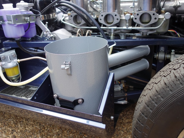
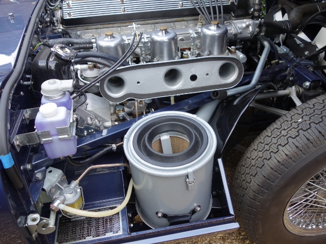
The pump raced when it wasn’t under load. So far, so good! However when the inlet pipe was placed in the bucket of paraffin it didn’t quite go as planned. It stopped immediately! I tried retuning the electric circuitry by repositioning the Hall Effect fork through its full arc of travel but it still refused to pump. It was a bit gutting having spent all that time and effort.

The technical department at Burlen Fuels thought it might be due to reverse pressure which would naturally slow the pump down. Although I wasn’t convinced as the outlet was simply pumping back into the supply bucket. I was running out of options and was starting to regret not buying a new pump!

I refitted the magnet attached to the end of the diaphragm spindle in the hope that this might be limiting its travel and therefore the strength of the pump. Eureka – the pump continued under load but at a much reduced rate, which would be expected.

The proof would be in the achieved flow rate which, over three tests, averaged out at 1.6 litres or 2.8 pints. Phew!

I was now happy that the pump was in working order and could be refitted to the car.

Aug 312012
 

The section in the service manual for removing the independent rear suspension (IRS) unit gave the false impression that it was simply a matter of disconnecting the handbrake cable, the hydraulic pipe and prop shaft, undoing the roll bar mounts and knocking off the radius arms. The IRS cage could then be lowered after unbolting the four cage mounts.

It probably is that simple for well maintained cars but mine had seized solid, resulting in bloodied knuckles and much cursing. In fact I couldn’t even get the wire wheels off as they were rusted to the hub splines! The brake connections and prop shaft were fairly easy to undo but everything else was struggle after struggle! The radius arms connect to cup fittings secured to underneath of the floor pan by what look like rivets. However the radius arms had well and truly rusted to the cups. Wooden wedges were hammered in but they still refused to budge.

I later found out from the E-Type forum that they are not rivets but something called Huck bolts, which are designed to shear in the event of an accident. I also found out others’ tricks to release the radius arms from the cups once the retaining bolts have been removed. Too late for my removal but no doubt they’ll be very useful in future. The first is to drive the car slowly backwards and forwards, with the aim that the changing loads breaks the radius arm/cup bond. The second is to chock the rear wheels and then jack up the front creating a load in the radius arms.

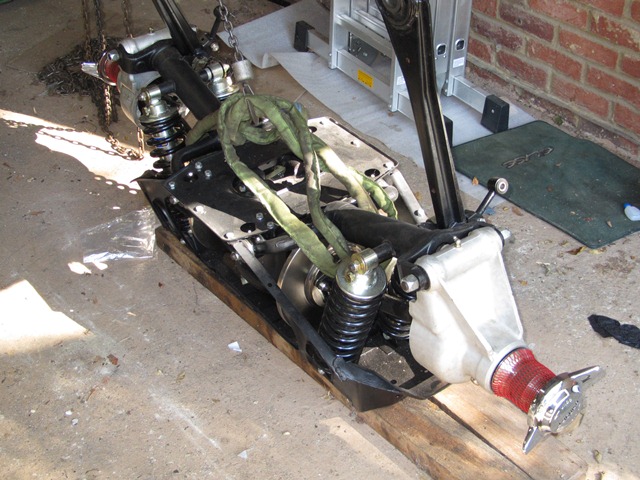
I briefly tried applying heat but all this did was burn the rubber bushes, producing acrid smoke. They eventually came free after applying penetrating oil over a period of several weeks and then jumping up and down on the end of a very long lever, inserted between the floor pan and the radius arm. To the untrained eye, the jumping up and down in a frustrated, childish manner while shouting ‘aaaargh!’ might have come across as a method of last resort …. but it worked!

The next setback was the removal of the roll bar. The bolts securing the mounting brackets were also seized but as they angled slightly downwards it wasn’t possible to apply penetrating oil so that it could soak in. Again I tried using localised heat but, like the radius arms, the bushes started to burn. By this time patience was in short supply, so I gave up and ground off the bolt heads to release the roll bar brackets.

The bolts securing the four IRS cage mounts had also rusted but fortunately they could be still undone. The main problem was the confined space so initially they could only be undone a 1/4 of a turn at a time. As I’d been unable to get the wheels off, it was rather an unconventional removal. Wooden blocks were placed under the cage’s base plate and the car raised away from the supported IRS.

The final dismantling of the IRS was equally unconventional for the same reason. The wheels and hubs were removed with the drive shafts and lower wishbones still attached and taken to a local garage so the hubs could be pressed out of the wheels. There was quite a build up of oil on the differential which suggested some of the seals might have perished. Although they’re interchangeable, and I didn’t know at the time, the aluminium hub carriers are not correct for the E-Type, which should have straight rather than sculptured sides.

 Posted by at 8:49 pm
Aug 312012
 

When I first contacted Hutsons, I was warned that they estimated it would be 10 months + before I would get the completed, painted body shell back, such was their current work load. So my aim was to get all the other components completed for its anticipated return in May 2011.

I tend to be rather optimistic (read extremely optimistic!) in the time it will take me to completed things. Even so I knew I wouldn’t be able to tackle everything in that time. The plan was to get the engine and gearbox reconditioned by reputable companies. In the meantime, this would give me the space and time to renovate and restore the other components.

I chose VSE to recondition the engine, based both on recommendations from others and price. I wanted to see their operation first, mainly out of interest, and to discuss the rebuild in person. So I headed off to see them in mid-Wales. It the last place you’d expect to find an engine reconditioning firm – it really was in the middle of nowhere in converted farm buildings with sheep for neighbours!

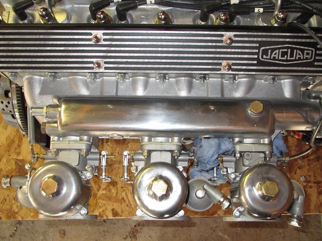
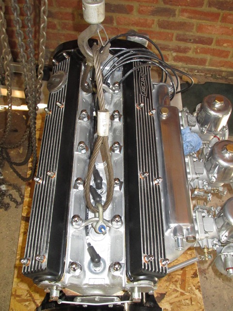
VSE offer a number of performance levels for their rebuilds and those that had recommended them suggested to go for maximum torque rather than headline BHP, which made good sense.

I think it’s all too easy to go over the top seeking greater performance with loony cams and excessively lightened clutch plates at the expense of drivability. So I opted for mildly tweaked performance which is in between their VS1 and VS2 levels, a 123 Electronic Ignition distributor and adapted to accept a modern oil filter.

The first thing to do was to build a suitably sturdy trolley which was low to the ground to avoid the problems encountered during the engine removal. The trolley base was made from two sheets of 22mm wooden boarding with castors that could be bolted directly to the base.

Even this wasn’t strong enough partly because I had used a coarse resin chipboard. Additional sections of wood were attached to the underside to stop it bowing in the middle.

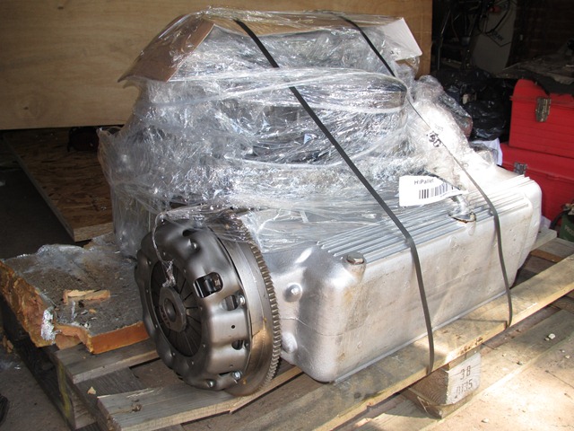
It was far easier to get the engine delivered rather than trek out to mid-Wales again. In due course the engine arrived wrapped in cellophane, strapped to a pallet.

Unfortunately the body shell hadn’t even been started at this point which was annoying. My regret is that, if I’d have know how long it eventually took I’d probably have taken on the rebuild of the engine myself, farming out the machining tasks.

Below are a few more photos of the reconditioned engine, more for interest than anything specific to mention …..