
Time pressures delayed the full electrical shakedown testing until after the engine was up and running. Power is only required to the ignition and fuel pump circuits to start the engine so all the other fuses were removed. Having said that, I did end up fitting the fuse for the instrument voltage regulator in order to obtain oil pressure and temperature readings while the engine was running.
The other fuses were now fitted in turn, stopping to test each of the components they fed, before moving on to the next fuse. The resulting snagging list was encouragingly minor:
- The main beam can’t be flashed from the indicator stalk
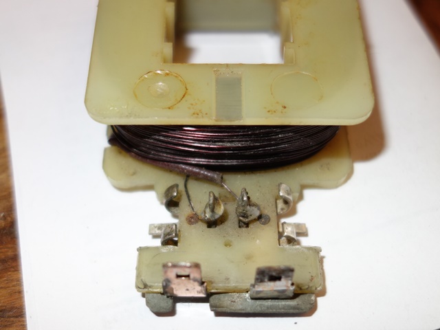
- The original hazard flashing unit is on the blink!
- The brake fluid warning light isn’t coming on
- The wiring to the rear brake and sidelights have been crossed over
- One of the cooling fans is a little noisy and spins the wrong way!
- The heater fan is making contact with the housing
- Neither the washer or wipers work
- Only one horn worked
Overall I was quite pleased with that for a first test. Especially as it was the first time the cooling fans and wiper motor had been tested since I rebuilt them and the washer, wiper, brake fluid warning light and horn were all simply missing earth connections. So easily solved.
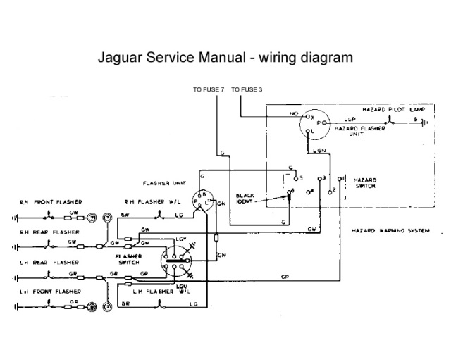
Indicators and hazard lights
There was a fair amount of head scratching when wiring up the hazard warning light switch. The part number identified it as a hazard switch from an XJ6 and its pin connections conflicted with those in the Illustrated Parts Manual!
| Hazard wiring diagram | Hazard switch wiring |
|---|---|
 |
 |
So I attempted to go back to first principles (or my understanding of them!) to work out the correct wiring. The one thing that was puzzling me was why separate indicator and hazard flasher units were used. They are essentially performing the same role – converting a constant DC supply into a square wave, with a suitable duty cycle to provide the correct flash duration and frequency.
The light bulb moment came when reading the requirements to pass an MOT. The hazard lights must be able to operate without a key in the ignition while the indicators are only powered when the ignition switch is on. The other difference is the power rating as the hazard unit needs to draw more current drive both sets of indicator lights at the same time.
The duty cycle of the unit is achieved by a bimetallic strip which expands and contracts depending on whether current is flowing. When the indicators are on, the current generates heat in the two metals, which expand at different rates. This causes the strip to move away from its contact and break the circuit. Without a current, the strip rapidly cools and the circuit is re-established allowing current to flow once more and the process to repeat.
Therefore the flashing frequency or ‘duty cycle’ is directly related to the rate of expansion/contraction of the bimetallic strip, which is a function of the current flowing. This is why modern LED indicator bulbs often do not work on classic cars as they draw far less current and therefore may not generate sufficient heat to switch the traditional units. Modern transistor based units are available to overcome the problem.
Therefore the switch needed to have the following connections:
Hazard switch in OFF position
- Indicator flashing unit is introduced into the circuit (the two green wires are connected)
- Hazard flashing unit is cut out of circuit (connections between the LGN, GR & GW wires are broken)
- The indicators can then be operated via the switches built into the indicator stalk
Hazard switch in ON position
- Indicator flashing unit is cut out of circuit (by removing power to its green wire)
- Hazard flashing unit is introduced (by connecting its LGN output to both the GR & GW indicator feeds)
The only problem was the random frequency of the hazard flashing which was easily solved by fitting a new flasher unit.
Cooling Fans
The S2 cars have an otter switch to turn on the cooling fans at its rated temperature and requires a special connector, which has been on back order for ages. A spare dash switch was rigged up in its place so the fans could be switched on and off at will, which would be useful when testing and tuning the engine. The first fan spun up and ran smoothly and quietly, which was very pleasing, as they hadn’t been bench tested after their refurbishment.
However the operation of the second fan was noisier because the blade was not quite square on the armature shaft, causing vibrations. Removing it was a fiddly process with the engine bay completed so I was cursing not having bench tested it!
But more importantly, the motor was rotating the wrong way, pushing air forward towards the radiator rather than drawing air through it. Its effect would be worse than having no fan at all. When travelling at speed there would be a natural flow of air through the radiator. Having a fan blow against this flow would reduce the cooling ability.
It is rather odd because reversing the supply polarity of series wound DC motors (and indeed shunt wound motors) does not reverse the direction of rotation. The only way to rectify this would be to reverse the connections on either the field or the rotor windings (but not both!).
The rotating force (torque) on the armature shaft is the result of the interaction of the magnetic fields of the armature and the field winding – opposite poles attract, like poles repel. The directions of these magnetic fields are dependant on the direction of the current following through them.
Therefore changing the polarity of the power supply does not reverse the direction of rotation because both the field and armature currents will be reversed and therefore both magnetic fields. A double negative if you like, that cancels each other out!
The only practical option for these Lucas motors was to reverse the field winding, which was a very simple job.
| Field wires just needed swapping | All sorted – an easy soldering job |
|---|---|
 |
 |
The fan now rotates in the correct direction to draw air rearward through the radiator. The fan was also re-seated to stop the fan vibrating so much.
I was trying to fathom an explanation as to why the motors were rotating the wrong way and then recalled that I had difficulty dismantling the two motors I’d acquired many moons ago, at the start of 2012. They were of the same design but had the fans mounted the wrong way round.
The person had indicated they were selling them as they had upgraded to modern fan units. However I suspect they had sourced motors from a different vehicle and noticed they were turning the wrong way. They had then mistakenly concluded mounting the fans the wrong way round would rectify the situation, rather than just improve their efficiency in making things worse!!
Wiper motor & Intermittent module

Intermittent control above
brake warning light
I’d decided to fit the Hella intermitted wiper module that other E-Type forum members had advocated. It works independently from the two speed wiper switch on the dash and the modification is reasonably discreet and reversible. The intermittent control uses the hole in the dash for the rear window heater on the FHC, which is blanked off on the OTS cars.
Like the hazard warning switch, the part number on the wiper motor switch also suggested it had originally come from an XJ6. The problem was the connected terminals were different to the correct switch (OFF 5-7, Normal 4-5, Fast 2-4) and so it was another case of trying to work out how it should be wired.
The combination of common sense and trial and error eventually produce the correct operation, which differed from the wiring suggested by the forum post. I’ve wired intermittent module into the ULG feed rather than the suggested YLG wire, which is for operating the motor at high speed.
At the same time, I also decided to add a jumper lead (with an inline diode) from the washer switch to the slow speed supply to the motor. Therefore the wipers now operate automatically while the washer switch is pressed. The diode is needed to stop it working in reverse, with the washer operating when the wipers are switched on!
Heater Motor
A complete new heater unit had to be fitted as the original had largely rusted away. The resistor, providing the dual speed operation, is riveted to the base plate of the heater motor. I’d foolishly assumed the new units would be supplied complete with the resistor already attached – dream on!
The resistor is sold separately and, due to the lack of clearance, requires the base plate to be removed from the motor in order to fix it. The wires are then soldered to the resistor rather than via spade connectors. As a result, the loom has bullet connectors built in, approx 6″ from the end of the wires, to allow the motor to be separated from the loom if it needs to be removed for servicing.
| Resistor provides 2-speed operation | Loom wires are soldered in place | Fitting was tricky due to the engine frame |
|---|---|---|
 |
 |
 |
However the looms didn’t come with the rather crucial two wires needed from the resistor to the motor terminals! The other issue came trying to re-fit the motor to the heater housing which had already been attached to the bulkhead. Removing it wouldn’t be an easy option as the cooling system had now been filled.
The reason the motor and fan cage couldn’t be fitted onto the housing was the base plate fouled on the engine frame. It was necessary to detach the fan cage from the motor by undoing the clamping grub screw. This allowed the cage to be fed up into the housing and then reconnected to the motor once the motor was clear of the engine frame.
The fan just had to be re-attached ever so slightly nearer the motor to cure the fouling problem found during the initial shakedown tests.
Alternator testing
The electrical component that I’d been putting off testing was the re-wired alternator. The modifications to the alternator were more far reaching than any of the other electrical work and so there was more scope for things to go wrong. Once all the other electrical issues had been resolved, I fitted the alternator belt and prepared to start the engine. Would it work or would it blow any of the other components?
Unfortunately I didn’t have a suitable ammeter to measure the theoretical maximum output of approx 60 Amps and so my testing was limited to measuring the voltage at the battery terminals with a multi-meter:
- With the engine off, the terminal voltage should be approx 12.7v
- When running at idle, the alternator should raise the terminal voltage to around 13.9v-14.3v
- The terminal voltage should reach between 14.3-14.6v running at 2500 rpm
In theory if the alternator output drops from the last two levels then it points to the failure of one or more of the rectifying diodes. If it rises above 14.8v, then the 4TR voltage regulator unit is not limiting the maximum voltage and needs to be replaced to avoid overcharging the battery. However I also have to consider that any lack of output could also be due to the additional diodes introduced to self-energise the field winding.
It was a welcome anti-climax that the initial test appeared to be successful. Although I’ll need to do further checks to ensure it’s charging when the car is run for a longer period.