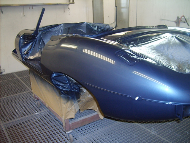
My initial plan for the renovation of the alternator was mainly cosmetic but also to check, and replace where necessary, the slip rings and brushes. Slip ring wear can be determined by removing the brush holder and they had definitely seen better days. They were quite heavily grooved so the renovation soon turned into a full rebuild. At this point I started to research the workings of the Lucas 11AC alternator to help understand what I was taking on. I came across the Rootes website which covers an upgrade of the internals to a more modern design.
The upgrade involves adding an additional three rectifying diodes, the output of which will be used to energise the field coil. The main benefits would be that by changing to be self-energising, the rotor winding wouldn’t be susceptible to burn out in the event of the alternator belt failing, there’s no need for the alternator relay or 3AW ignition light relay and it provides a “softer” start, therefore providing better protection for the other electrical components.
Unfortunately I had destroyed the 3AW relay when the car was dismantled – one of its spade connections was more strongly attached to the female connector on the wiring loom than the relay itself and broke free! I’d also read that some viewed the relay as a weak point in the charging system and prone to failure, although modern solid state units are available.
It made sense to make this upgrade while the alternator was dismantled and would avoid needing to source a new 3AW unit. The upgrade didn’t appear to be too complex and hopefully within my DIY skills!
|
|
|
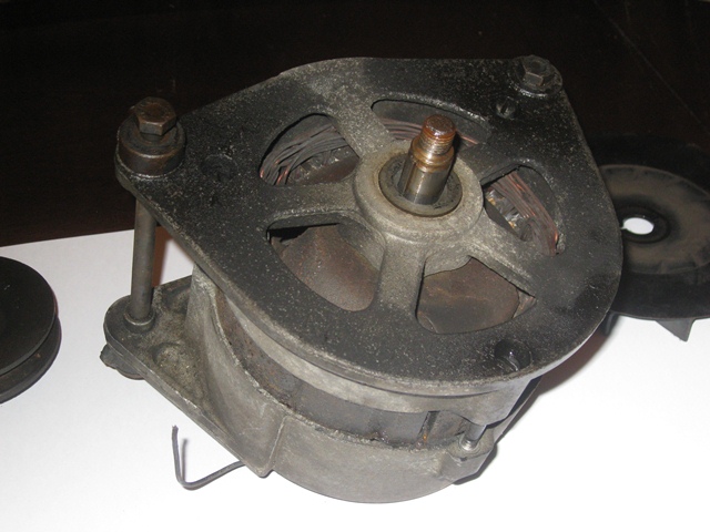
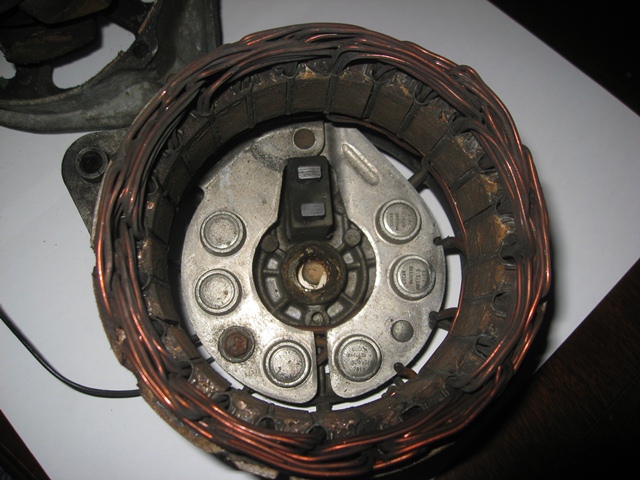
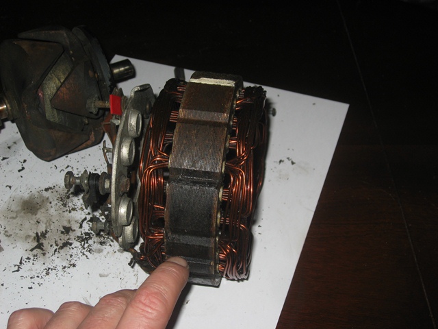
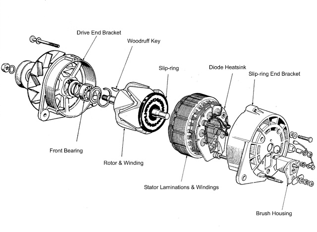
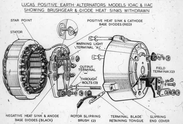
The main components of the Lucas 11AC alternator are; the alloy drive end bracket, the rotor, the stator laminations & windings, the rectifying diode heatsink and the alloy slip-ring end bracket. The diode heatsink is attached to the rear casing via three insulated threaded studs, which act as the electrical terminals. The stator is clamped between the two end brackets with the rotor passing through the middle.
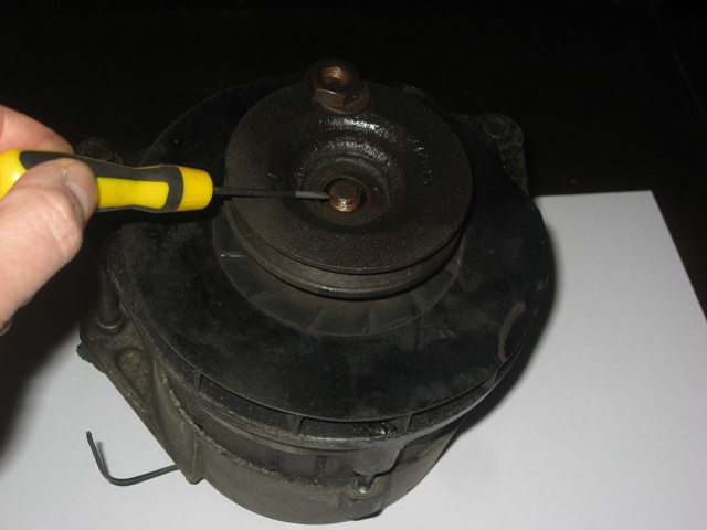
The dismantling of the alternator proved to be much harder than the other electrical components. This was because the design uses a woodruff key which, despite all efforts, was refusing to come out. The woodruff key is a semi-circular disk that is inserted into a slot in the alternator shaft, leaving a protruding tab. This tab mates with key slots in the belt pulley and cooling fan to prevent them from rotating relative to the shaft. The pulley and fan are held in place by a retaining shaft nut and can be withdrawn, once the nut has been removed, to reveal the key.
The difficulty in removing the key was that it did not protrude enough to enable a drift to get onto the end of the key with a sufficient angle away from the shaft. After many frustrating hours getting nowhere, I decided to do some research on the internet in the hope that I would find useful tips on how to remove them. After many frustrating hours surfing the internet and getting nowhere, except for pearls of wisdom as useful as a chocolate teapot (“then remove the key with pliers”), I left it for several days to have a re-think.
In the meantime the rest of the alternator was dismantled by removing the three clamping bolts holding the unit together. This enabled the alternator to be split in half; the front drive end bracket & rotor and the rear slip ring end bracket with the attached rectifying diode heatsink and stator.
As mentioned, the diode heatsink is attached to the rear casing via three threaded terminal posts. Once the external retaining nuts have been removed from the terminals, the stator and diodes heatsink can be withdrawn. The two are connected by the wires for the three stator windings.
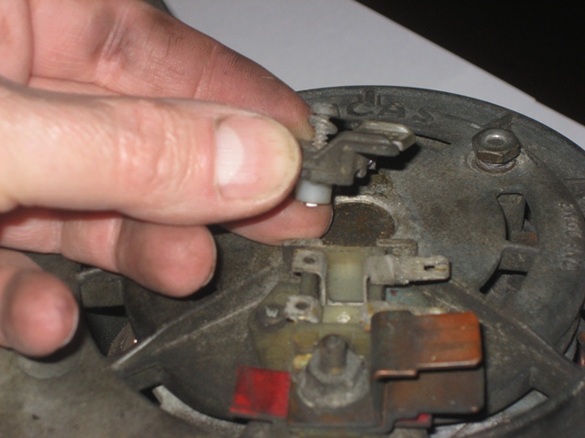
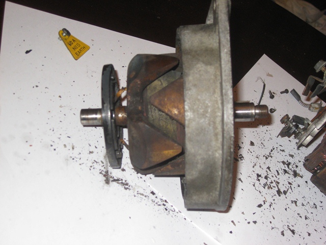
Care was taken to note the various insulating washers and fittings on the terminal posts. Both the B+ and AL posts are insulated from the slip ring end bracket while the third terminal post acts as the negative earth connection. The plastic housing holding the sprung slip ring brushes was removed, followed by pressing out the rotor shaft bearing from the rear casing.
I could put it off no longer – the woodruff key had to be removed. The solution that finally worked was very Heath Robinson, essentially using a vice to press the bottom of the key into the shaft. This caused the key to rotate in the slot resulting in pushing the upper part ever so slightly outwards but enough to get a drift onto it. It still required a reasonable amount of force to drift it out but at least I could now continue.
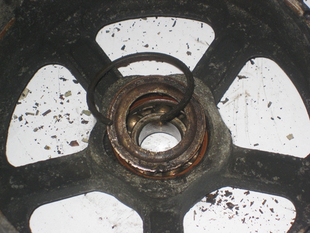
Now the key had been removed the rotor and front casing could be separated. All that remained was to remove a circlip holding in the front rotor bearing so it could be pressed out. The bearing had almost seized solid and couldn’t be rotated by hand so I was glad I had decided to overhaul the whole unit. The two end casings were then sent away for ultrasonic cleaning while parts were sourced for the upgrade/rebuild.