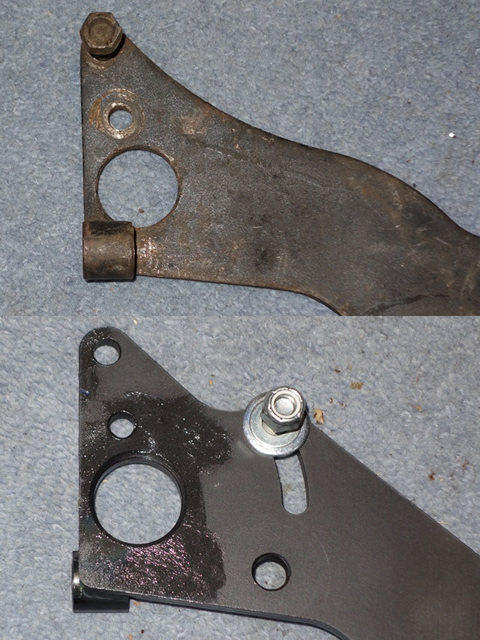
One of the first modifications I’d decided to make was the change to an adjustable reaction plate for the torsion bars. In part the decision was due to the enormous trouble I’d had removing the torsion bars and reaction plate.
Also, even though the front suspension should only need to be set up once, if there was some settling of the suspension after the rebuild, subsequent fettling would be far easier. So I purchased an adjustable reaction plate from Rob Beere and followed Bob Skelly’s excellent installation guide.
![]() – PDF Version
– PDF Version
 I’d planned to install the front suspension and torsion bars on two previous occasions. However, both times, progress had been thwarted due to some other fitting ‘difficulties’ that had been encountered. The first when installing the IRS and subsequently the engine.
So it shouldn’t have come as a surprise that fitting the reaction plate would be equally challenging! The first problem was the adjustable reaction plate was approximately 3-4mm wider than the original. The tubes for the bolts securing the plate to the underfloor channels protruded much further beyond the outer edges.
Rob Beere suggested using a pry bar and the need for a tight fit, which may well need hammering to ‘persuade’ it into position. If this didn’t work, the ends of the tubes could be ground down slightly to fit. No matter what I tried I couldn’t get it to fit and so had to resort to the latter.
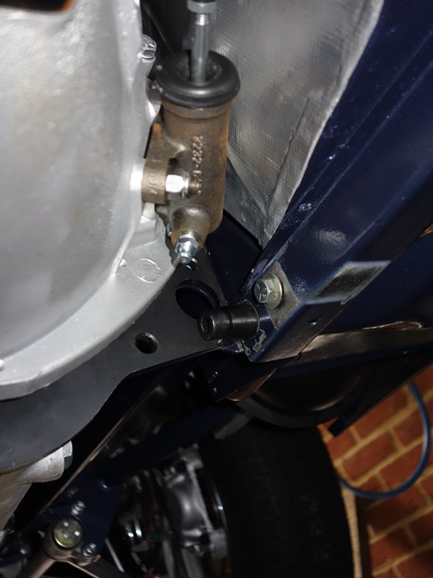 Even so, it still required hitting home with the nylon hammer. The various attempts to get the reaction plate to fit resulted in some damage to the paint work, which will need to be repaired.
Fortunately there are a number of other adjacent areas that still need to be touched up, where the chassis was attached to the support frame during painting. So these can all be tackled at the same time before the exhaust is fitted.
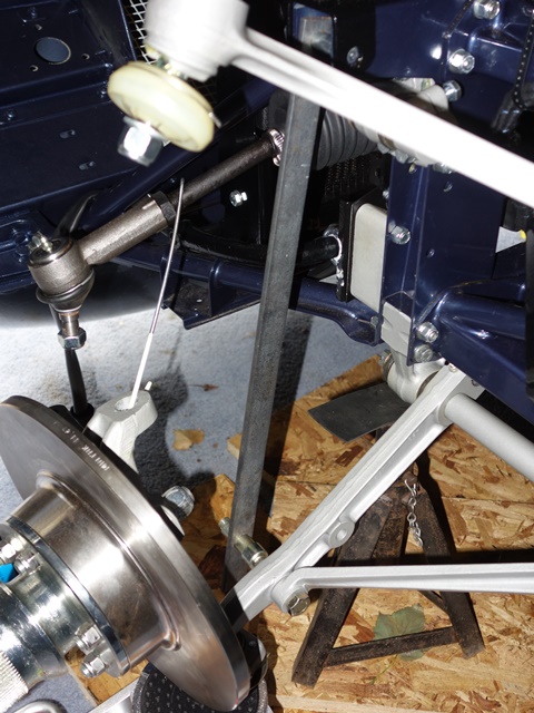
It was surprising to see that the new clutch slave cylinder had started to show some surface rust, even in the short time since the transmission was installed. I’ll have to treat it with some Dinitrol hard wax asap.
Bob’s instructions suggested tightening the large Allen key bolts once the upper bolts had been inserted. However I had slight alignment issues with all the mounting bolts and the torsion bar ‘ear’ brackets. Once the Allen and upper bolts were tightened, it was impossible to fit the remaining bolts and brackets.
 I found it was necessary to have everything initially finger tight, which enabled a screwdriver to be inserted in bolt holes to pry the other mounting holes in the frame into alignment with those in the reaction plate.
The fitting order that worked for me was the large Allen bolts followed by the ‘ear’ brackets, the upper bolts and finally the lower pre-cut bolts.
Only once all these were in place could everything, except the bolt through the ‘ear’, be fully tightened. It is worth reiterating that:
i) the Allen bolts need to be tightened before the adjusting cam is fitted, as the nut securing the cam obstructs access to the head of the Allen bolt
ii) the ear brackets needs to be at the top of their permitted travel before tightening the lower pre-cut bolts.
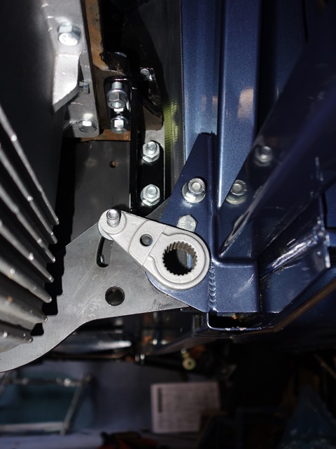
 I also followed the advice of labelling the cam steps and then painting the outer face with some clear lacquer. However I didn’t bother highlighting the edges of the steps as I thought this was a bit of overkill.
With hindsight, I think not adding the highlights was a slight mistake. It would have provided a better visual guide to ensure the step of the cam is parallel with the edge of the torsion bar ‘ear’ bracket.
It’s not a major problem, provided there’s sufficient light when setting the cams. If I were to do it again, I’d use two bright, contrasting colours to paint alternate step edges.
I’d not been looking forward to fitting the torsion bars. I hadn’t been able to dismantle them in the conventional manner, described in the various service manuals. There wasn’t even a slight hint of movement in the torsion bars despite some very hefty blows wielding a club hammer. In the end, as an act of self-preservation, I conceded defeat and removed each side of the suspension as single units.
Time for some (dubious) Maths – the torsion bar setting link
The shock aborber is replaced by a fixed length link to provide a datum point when setting the torsion bars. This should then give the correct ride height, although the adjustable reaction plate would then come into its own if it needed subsequent tweaking. The setting link for the early cars was 17 13/16″, however this had increased to 17 31/32″ for the S2 cars.
I’d obtained some replacement torsion bars at Stoneleigh but hadn’t realised at the time that almost all new torsion bars are ‘uprated’. The standard bars are 0.77″ in diameter while the replacements were 0.85″. As a result, the bars will be stiffer, so using the recommended setting link length would result in the ride height being too high …. but by how much?
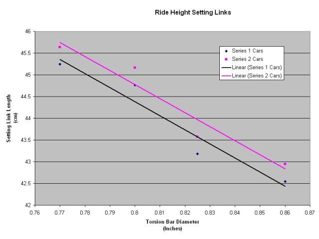 After some research I found that Classic Jaguar in America had produced a chart with recommended setting link lengths for various torsion bar diameters.
Unfortunately they don’t have a figure for 0.85″ bars so I thought I’d plot their recommendations in order to determine the link length required. The graph wasn’t what I was expecting, with a linear relationship between the setting link length and the torsion bar diameter.
Hmmmm! Perhaps I’m missing something as I thought the torsional stiffness or angular deflection of a solid bar was inversely proportional to the diameter to the power of 4. Still, without anything better to work from, using a linear calculation the setting link length needed was 43.1cm.
Fitting of the torsion bars
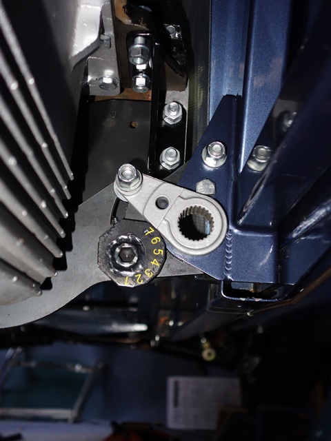
 The calculated length of the setting link should give me roughly the correct ride height (fingers crossed etc). So I chose to set the reaction plate cam to the mid-setting ‘4’ and will be able to raise or lower the ride height if it’s not exactly right. With the setting link in place and the ‘ear’ bracket locked at setting ‘4’, the rotational positions of the front and rear splines in the suspension are fixed.
The torsion bar has a different number of splines at each end – 25 at the rear and 24 at the front. This provides a high resolution vernier adjustment, allowing the torsion bars to be set very accurately and therefore the ride height. The fitting of the torsion bar is now a matter of trial and error, rotating the bar by one rear spline at a time until the front splines are perfectly aligned with those in the wishbone.
A rotation of one rear spline is equal to 14.4 degrees while it needs 15 degrees of rotation to move on by one front spline. Another way of looking at it is when the bar is turned by one rear spline, the relative position of the front splines is altered by 0.6 degrees, in the opposite direction to the direction of rotation. The front splines will align perfectly for one of the 25 possible orientations!!
 I had passed both splined ends of the torsion bars through their corresponding mating pieces a dozen or so times until I was satisifed it would only need three or four solid blows to hammer them home.
The torsion bar need to be passed rearward through the rear ‘ear’ mounting and then forward again until the front meets the splined hole in the lower wishbone. However the splines were still too tight a fit. It was necessary to carefully file the spline faces on the torsion bar until it only took one firm tap to fully engage the splines.
This enabled the torsion bars to be pushed forward by hand until the front was 1mm or so from the rear face of the wishbone. A tap with the hammer would then bring the bar up to the wishbone, at which point it was possible to determine if the splines were correctly aligned. I used a 12″ pointed concrete chisel for a drift, so the point could sit in the indentation at either end of the bars.
The mistakes I made were:
- Smothering Copperslip over the front splines on both the bar and within the wishbone
- Blindly accepting the view that it’s a matter of trial and error to find the best fit
The Copperslip did a splendid job of masking whether the splines were properly aligned and so it was all wiped off. The best time to apply it was once the correct orientation had been determined and the front splines had just engaged.
I followed the advice of adopting a methodical approach of rotating one spline at a time until an exact fit was achieved. After completing one full rotation I wasn’t convinced I was any the wiser. The correct orientation had probably been missed under the cover of Cooperslip!
It was only at this point did I sit down and work out the Maths of the relative 0.6 degree movement of the front splines for a rotation of one rear spline. A couple of minutes of thought up front would have saved several hours of grief and frustration with a club hammer! Armed with that knowledge, it was then quite easy to quickly home in on a small area of splines spanning the best fit.
As an example:
| Front spline need clockwise rotation | Result of rotating anti-clockwise by one rear spline | Eventually an exact alignment is reached |
|---|---|---|
|
|
|
|


In the left photo, gaps can clearly be seen between the splines. The front splines need to be rotated clockwise to close these gaps. The middle photo was taken after the torsion bar had be rotated anti-clockwise by one spline. The gaps have clearly been reduced.
Eventually an exact or best match is achieved. Although I found when viewed from the lower inboard (7-8 0’clock) the front spline alignment would look spot on. However when viewed from the top outboard position (1-2 O’clock), gaps would be visible.
I think this is because the angle between torsion bar and the wishbone isn’t exactly at 90 degrees. So the lower inbound splines start engaging before the top outbound splines. Hence why gaps are still visible from one view and not the other!
Finally the torsion bars were both in and I’ve now less fear of tackling them again in future.
 A pair of Lucas windtone 9H horns was fitted to the Series 2 E-Type, one emitting a high tone and the other the low tone. The excitation of the air column is achieved by vibrating an internal metal diaphragm, with the frequency of vibration and the shape of the horn snail or trumpet determining the note produced.
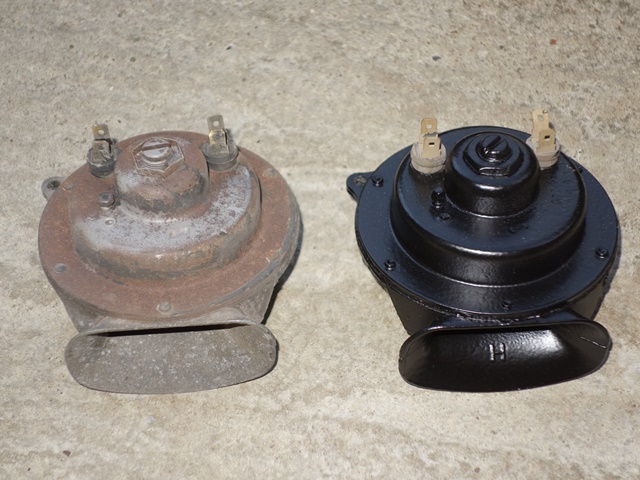 Rather optimistically I thought it would be just a matter of readjusting the gap to get it working again. Alas, there was something more seriously wrong inside so only the good one was repainted at this stage.
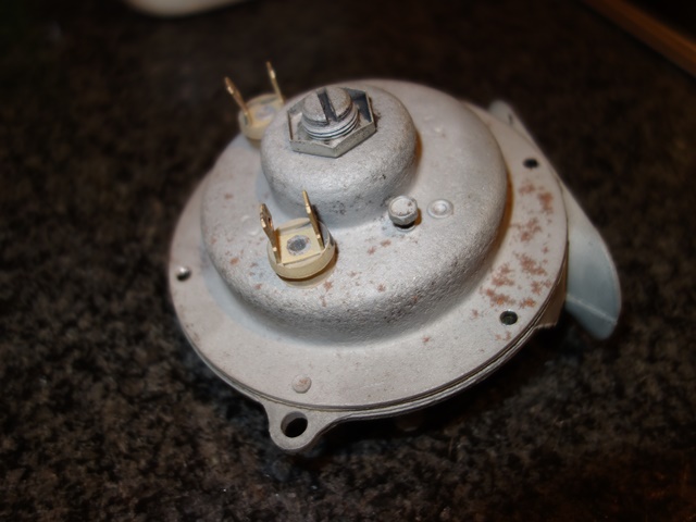
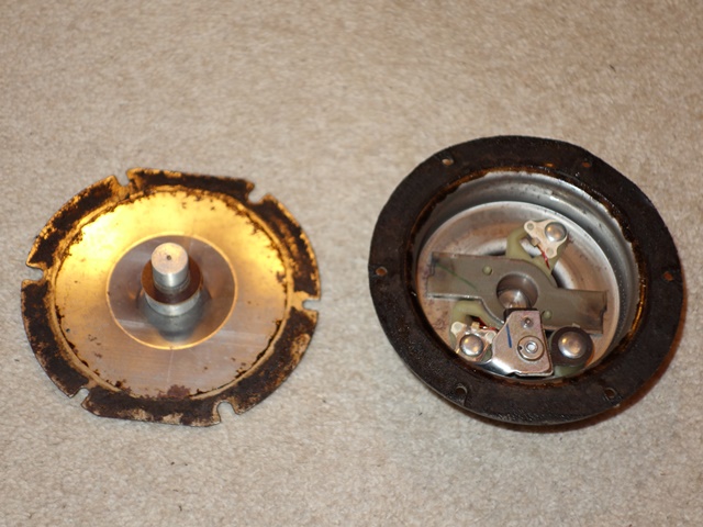
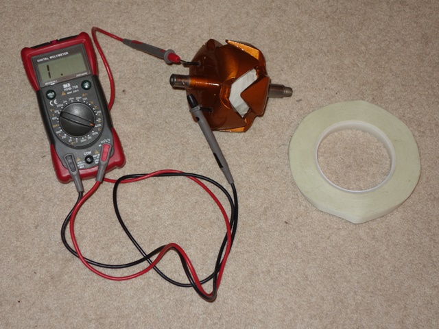
 The resistance of the contact points was around 7 ohms so a light rubbing with 400 grit wet and dry soon got this down to 0.8. Although I wouldn’t have thought this would stop the horn operating. I think the problem is with an external screw fitting which the service manual suggests should not be touched.
  As previously mentioned, the Rootes Parts website covers the
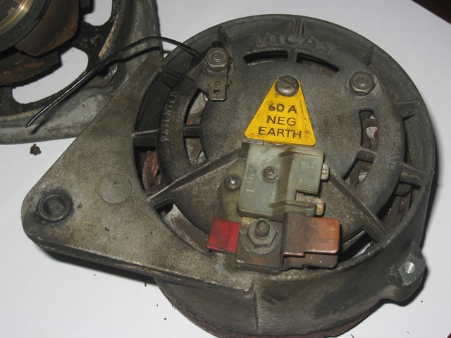
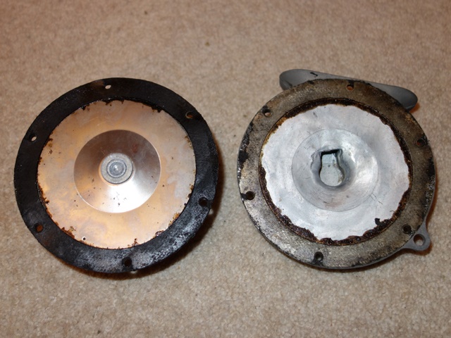
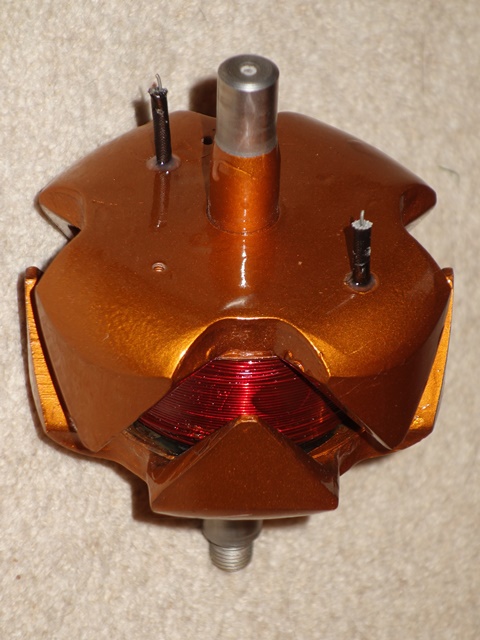
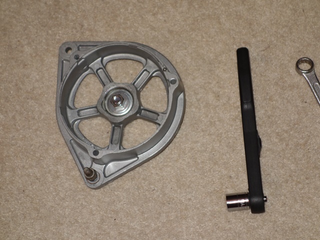
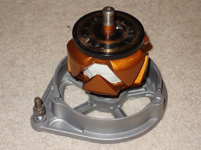
 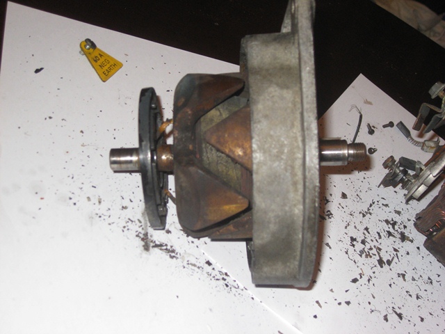 Three screws fix the split ring plate to the rotor. Once removed, the plate can be pulled away from the rotor to reveal the ends of the rotor field winding, which pass through the rear of the slip ring plate and are then soldered at the front to the brass slip rings.
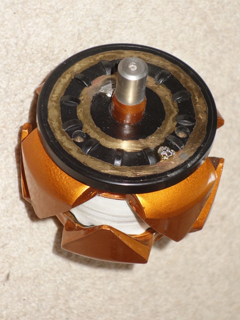
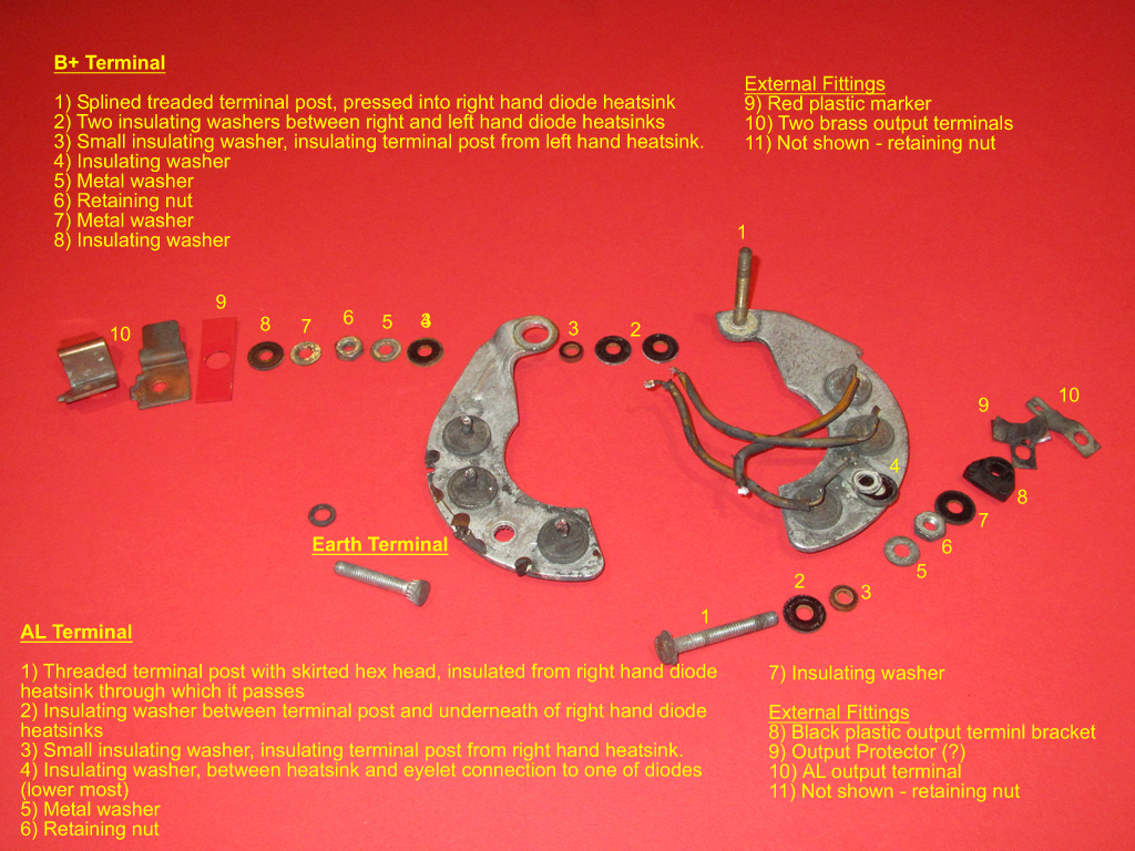
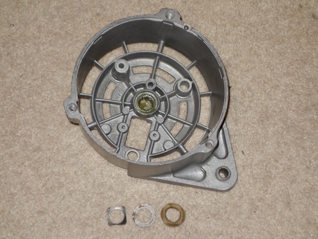
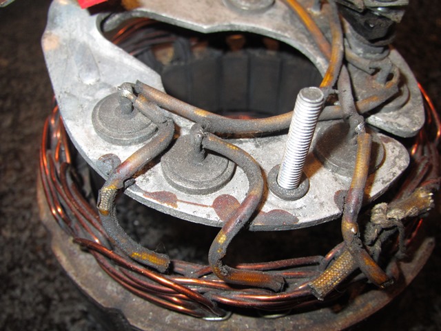 The rectifying diode housing and attached stator were removed from the rear housing by undoing the external nuts on the three terminal posts. Once again I had great trouble de-soldering the joints, this time connecting the stator windings to the diode housing.