Feb 102015
 

The green illumination of the dash gauges is achieved by plastic green filters within the gauges. However almost all of these filters had deteriorated due to their proximity to the incandescent bulbs. Some had actually melted due to the heat produced. I had therefore decided to ‘upgrade’ to LEDs after reading the conversion on the E-Type forum. For my conversion, I wanted to:

  • Retain having two brightness settings: Bright and Dim *
  • Switch between green and blue lighting

* – I couldn’t envisage a situation when I would want the side/head lights on but the dash not illuminated. So I have decided to drop the ability to turn off the dash illumination and have replaced the 3-way Panel switch with a 2-way switch.

Dimming the LEDs
The RGB LED strips have a common 12 volt supply and then one wire for each of the primary colours. The LEDs for a specific colour are turned on by connecting the corresponding wire to 0v, ie earth.

The amount of light produced by incandescent bulbs is linear to the current flowing through the bulb. Therefore accurate dimming of the bulbs is achieved by switching a suitably sized resistor into the circuit, in series with the bulbs.

Unfortunately this task is not as simple with LEDs. The light output for two ‘identical’ LEDs is not as predictable simply by reducing the voltage drop across them. The only reliable way to dim LEDs is rapidly switching the LED on and off. Above a certain switching frequency, the human brain cannot differentiate between when the LED is on and off. The perceived brightness is then the relative percentage of time the LED is on during one switching cycle.

Fortunately it’s possible to purchase small LED control units to perform this function. My initial trials using LEDs found that, without on/off switching, the light output was too great. Therefore two LED control units would be needed to control the brightness for both the Bright and Dim settings.

The other key difference, already mentioned, is that the 12v supply voltage is always connected. The individual LED colours are turned on by connecting their earth lead to a ‘floating earth’.

Note: this ‘earth’ is different from the car earth as when in dimming mode it will switch between 0v and 12v.

Green/Blue switching
The ability to switch between green and blue lighting would require the complete rewiring of:
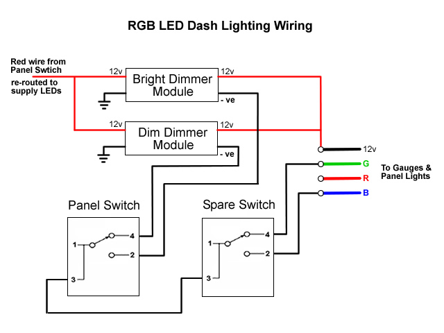
i) the panel switch to select either the ‘Bright’ or ‘Dim’ earth connection from the respective LED control module (rather than provide the 12 volt supply)

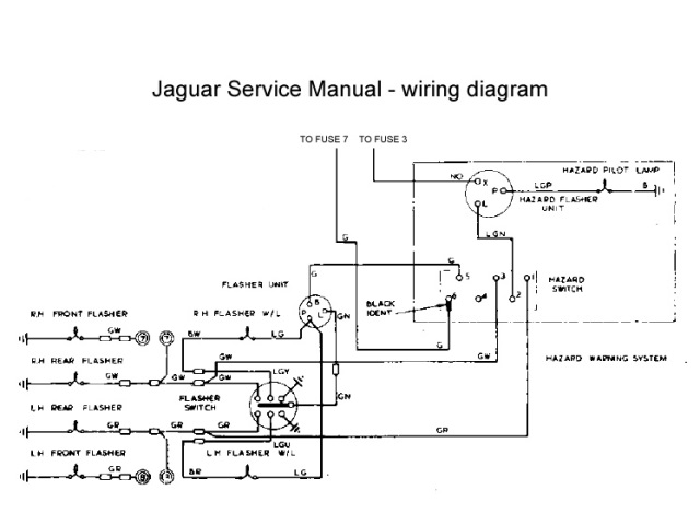
ii) the spare switch to then connect the selected earth to either the green or blue lead. After a few trials, I settled on the wiring diagram shown.

Both LED control modules are connected to the loom’s Red supply wire from Fuse 5, which is disconnected from the Panel Switch, and the car’s earth. The positive LED outputs from both control modules provide the 12v supply to the RGB cable.

New wiring is then needed to between the two switches for the earth connections to either the Blue or Green LED lead. Finally the gauges and switch legend LED strip are daisy chained together with 4-core RGB cabling.

Switch Legend Strip
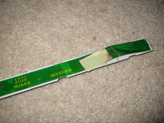
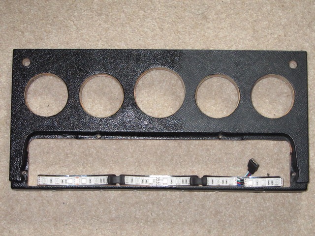
The switch legend is normally lit by three bulbs mounted in convex reflectors approximately 10cm in length. The green hue was achieved by a plastic green tape glued to the rear of the legend strip. However this has faded so it was now more of a mucky yellow colour. The tape was removed as the colour would now be provided by the LEDs.

Green tape provided legend colouring LED strips fitted to legend reflectors
The green colour of the backlighting was obtained by a coloured plastic strip Installation of the LEDs for the illumination of the switch legend.

{Note: the dash photo was taken midway through being cleaned/treated with Gtechniq Trim Restorer C4 – hence the half and half look!}

Dash Gauges
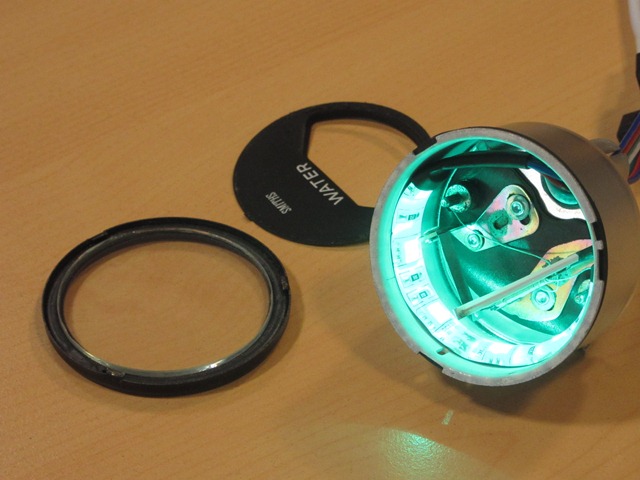
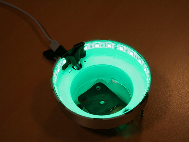
The seven gauges are all opened by rotating the rim until tabs on the rim align with cut-outs in the housing. This enables the rim and glass to be removed to install the LED strips.

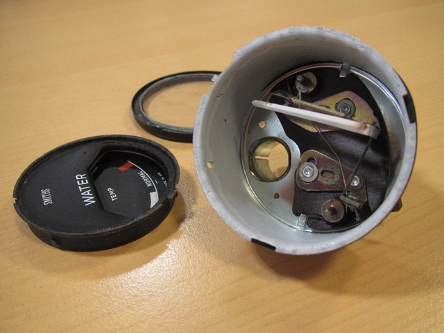
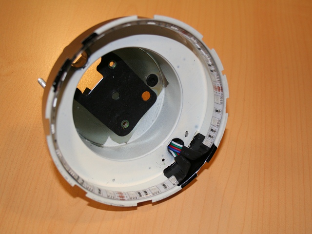
The internals of the smaller four gauges (water temperature, oil pressure, fuel and battery) are very similar where the mechanisms are permanently secured to the housing. These mechanisms are quite delicate so the dismantling and insertion of the 10cm LED strips needed to be done with some care.

These gauges have a face plate which has to be eased away from the underlying cup, which has the gauge’s scale printed on it. A small screwdriver can then be inserted under the rim of the cup to prise it away from the housing. Once loose, it’s a matter of rotating the cup to clear the fragile needle.

Six dash gauges and clock Face plate & cup removed LED strip inserted from the rear

It’s very easy to inadvertently solder the RGB earth contacts together so it was well worth testing the operation of the LEDs before rebuilding the gauges.

The clock proved to be more difficult even though the entire clock mechanism comes out with the face. It’s slightly larger than the other gauges and so can accommodate a 15cm strip. However the clearance between the housing and the clock mechanism wasn’t sufficient due to the clear, waterproof coating. This had to be peel off to fit.

Removing the waterproofing Cabling was a tight squeeze Comparing brightness of colours

The entire mechanisms for rev counter and speedometer are also removed with the gauge face, which allows unhindered access to stick the 35cm strip to the perimeter.

Rev counter housing Cable pass through bulb opening Testing prior to rebuilding

The downside of having the ability to switch between the two colours is it requires multi-core cable and so the installation is not so discreet. Even so, it will all be hidden from view once in place.

My first attempt was to use standard RBG cables and connectors but these provide to be temperamental and unlikely to stand the test of time. I therefore changed them to larger plug and socket terminals with internal, mini spade connectors which were also held together by a clip.
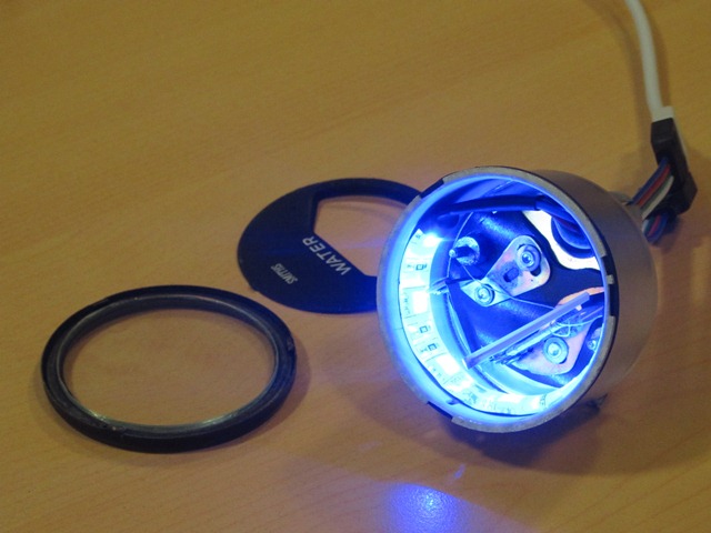
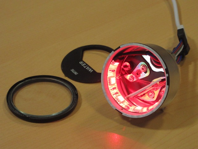
RGB connectors were unreliable Blue illumination without dimming Switched to green illumination

The other LED lighting was to illuminated the boot when the bootlid was opened. Two 25cm pure white LED strips were stuck to the underside of the tonneau top panel. Power was provided by running a wire from the permanent Brown fuse terminals and switched by a micro switch attached to the boot hinge.

Would I do the same upgrade again? Definitely not! Possibly just installing a single colour LED strip but the ability to switch between green and blue lighting resulted in unnecessary complexity. Just because it can be done, doesn’t mean it should be done!

 Posted by at 8:43 am
Nov 132014
 

Time pressures delayed the full electrical shakedown testing until after the engine was up and running. Power is only required to the ignition and fuel pump circuits to start the engine so all the other fuses were removed. Having said that, I did end up fitting the fuse for the instrument voltage regulator in order to obtain oil pressure and temperature readings while the engine was running.

The other fuses were now fitted in turn, stopping to test each of the components they fed, before moving on to the next fuse. The resulting snagging list was encouragingly minor:

  • The main beam can’t be flashed from the indicator stalk
  • The original hazard flashing unit is on the blink!
  • The brake fluid warning light isn’t coming on
  • The wiring to the rear brake and sidelights have been crossed over
  • One of the cooling fans is a little noisy and spins the wrong way!
  • The heater fan is making contact with the housing
  • Neither the washer or wipers work
  • Only one horn worked

Overall I was quite pleased with that for a first test. Especially as it was the first time the cooling fans and wiper motor had been tested since I rebuilt them and the washer, wiper, brake fluid warning light and horn were all simply missing earth connections. So easily solved.

Indicators and hazard lights
There was a fair amount of head scratching when wiring up the hazard warning light switch. The part number identified it as a hazard switch from an XJ6 and its pin connections conflicted with those in the Illustrated Parts Manual!

Hazard wiring diagram Hazard switch wiring

So I attempted to go back to first principles (or my understanding of them!) to work out the correct wiring. The one thing that was puzzling me was why separate indicator and hazard flasher units were used. They are essentially performing the same role – converting a constant DC supply into a square wave, with a suitable duty cycle to provide the correct flash duration and frequency.

The light bulb moment came when reading the requirements to pass an MOT. The hazard lights must be able to operate without a key in the ignition while the indicators are only powered when the ignition switch is on. The other difference is the power rating as the hazard unit needs to draw more current drive both sets of indicator lights at the same time.

The duty cycle of the unit is achieved by a bimetallic strip which expands and contracts depending on whether current is flowing. When the indicators are on, the current generates heat in the two metals, which expand at different rates. This causes the strip to move away from its contact and break the circuit. Without a current, the strip rapidly cools and the circuit is re-established allowing current to flow once more and the process to repeat.

Therefore the flashing frequency or ‘duty cycle’ is directly related to the rate of expansion/contraction of the bimetallic strip, which is a function of the current flowing. This is why modern LED indicator bulbs often do not work on classic cars as they draw far less current and therefore may not generate sufficient heat to switch the traditional units. Modern transistor based units are available to overcome the problem.

Therefore the switch needed to have the following connections:

Hazard switch in OFF position

  • Indicator flashing unit is introduced into the circuit (the two green wires are connected)
  • Hazard flashing unit is cut out of circuit (connections between the LGN, GR & GW wires are broken)
  • The indicators can then be operated via the switches built into the indicator stalk

Hazard switch in ON position

  • Indicator flashing unit is cut out of circuit (by removing power to its green wire)
  • Hazard flashing unit is introduced (by connecting its LGN output to both the GR & GW indicator feeds)

The only problem was the random frequency of the hazard flashing which was easily solved by fitting a new flasher unit.

Cooling Fans
The S2 cars have an otter switch to turn on the cooling fans at its rated temperature and requires a special connector, which has been on back order for ages. A spare dash switch was rigged up in its place so the fans could be switched on and off at will, which would be useful when testing and tuning the engine. The first fan spun up and ran smoothly and quietly, which was very pleasing, as they hadn’t been bench tested after their refurbishment.

However the operation of the second fan was noisier because the blade was not quite square on the armature shaft, causing vibrations. Removing it was a fiddly process with the engine bay completed so I was cursing not having bench tested it!


But more importantly, the motor was rotating the wrong way, pushing air forward towards the radiator rather than drawing air through it. Its effect would be worse than having no fan at all. When travelling at speed there would be a natural flow of air through the radiator. Having a fan blow against this flow would reduce the cooling ability.

It is rather odd because reversing the supply polarity of series wound DC motors (and indeed shunt wound motors) does not reverse the direction of rotation. The only way to rectify this would be to reverse the connections on either the field or the rotor windings (but not both!).

The rotating force (torque) on the armature shaft is the result of the interaction of the magnetic fields of the armature and the field winding – opposite poles attract, like poles repel. The directions of these magnetic fields are dependant on the direction of the current following through them.

Therefore changing the polarity of the power supply does not reverse the direction of rotation because both the field and armature currents will be reversed and therefore both magnetic fields. A double negative if you like, that cancels each other out!

The only practical option for these Lucas motors was to reverse the field winding, which was a very simple job.

Field wires just needed swapping All sorted – an easy soldering job

The fan now rotates in the correct direction to draw air rearward through the radiator. The fan was also re-seated to stop the fan vibrating so much.

I was trying to fathom an explanation as to why the motors were rotating the wrong way and then recalled that I had difficulty dismantling the two motors I’d acquired many moons ago, at the start of 2012. They were of the same design but had the fans mounted the wrong way round.

The person had indicated they were selling them as they had upgraded to modern fan units. However I suspect they had sourced motors from a different vehicle and noticed they were turning the wrong way. They had then mistakenly concluded mounting the fans the wrong way round would rectify the situation, rather than just improve their efficiency in making things worse!!

Wiper motor & Intermittent module


Intermittent control above
brake warning light

I’d decided to fit the Hella intermitted wiper module that other E-Type forum members had advocated. It works independently from the two speed wiper switch on the dash and the modification is reasonably discreet and reversible. The intermittent control uses the hole in the dash for the rear window heater on the FHC, which is blanked off on the OTS cars.

Like the hazard warning switch, the part number on the wiper motor switch also suggested it had originally come from an XJ6. The problem was the connected terminals were different to the correct switch (OFF 5-7, Normal 4-5, Fast 2-4) and so it was another case of trying to work out how it should be wired.

The combination of common sense and trial and error eventually produce the correct operation, which differed from the wiring suggested by the forum post. I’ve wired intermittent module into the ULG feed rather than the suggested YLG wire, which is for operating the motor at high speed.

At the same time, I also decided to add a jumper lead (with an inline diode) from the washer switch to the slow speed supply to the motor. Therefore the wipers now operate automatically while the washer switch is pressed. The diode is needed to stop it working in reverse, with the washer operating when the wipers are switched on!

Heater Motor
A complete new heater unit had to be fitted as the original had largely rusted away. The resistor, providing the dual speed operation, is riveted to the base plate of the heater motor. I’d foolishly assumed the new units would be supplied complete with the resistor already attached – dream on!

The resistor is sold separately and, due to the lack of clearance, requires the base plate to be removed from the motor in order to fix it. The wires are then soldered to the resistor rather than via spade connectors. As a result, the loom has bullet connectors built in, approx 6″ from the end of the wires, to allow the motor to be separated from the loom if it needs to be removed for servicing.

Resistor provides 2-speed operation Loom wires are soldered in place Fitting was tricky due to
the engine frame

However the looms didn’t come with the rather crucial two wires needed from the resistor to the motor terminals! The other issue came trying to re-fit the motor to the heater housing which had already been attached to the bulkhead. Removing it wouldn’t be an easy option as the cooling system had now been filled.

The reason the motor and fan cage couldn’t be fitted onto the housing was the base plate fouled on the engine frame. It was necessary to detach the fan cage from the motor by undoing the clamping grub screw. This allowed the cage to be fed up into the housing and then reconnected to the motor once the motor was clear of the engine frame.

The fan just had to be re-attached ever so slightly nearer the motor to cure the fouling problem found during the initial shakedown tests.

Alternator testing
The electrical component that I’d been putting off testing was the re-wired alternator. The modifications to the alternator were more far reaching than any of the other electrical work and so there was more scope for things to go wrong. Once all the other electrical issues had been resolved, I fitted the alternator belt and prepared to start the engine. Would it work or would it blow any of the other components?

Unfortunately I didn’t have a suitable ammeter to measure the theoretical maximum output of approx 60 Amps and so my testing was limited to measuring the voltage at the battery terminals with a multi-meter:

  • With the engine off, the terminal voltage should be approx 12.7v
  • When running at idle, the alternator should raise the terminal voltage to around 13.9v-14.3v
  • The terminal voltage should reach between 14.3-14.6v running at 2500 rpm

In theory if the alternator output drops from the last two levels then it points to the failure of one or more of the rectifying diodes. If it rises above 14.8v, then the 4TR voltage regulator unit is not limiting the maximum voltage and needs to be replaced to avoid overcharging the battery. However I also have to consider that any lack of output could also be due to the additional diodes introduced to self-energise the field winding.

It was a welcome anti-climax that the initial test appeared to be successful. Although I’ll need to do further checks to ensure it’s charging when the car is run for a longer period.

Jun 152014
 

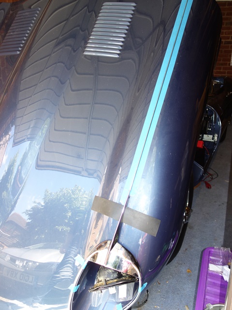
Before the headlights can be fitted, the bonnet electrics need to be completed while there’s still access.

The addition of headlamp relays had been made and so all that remained was to run the bonnet loom from the 10-way connector mounted behind the LH headlamp ‘sugar scoop’ to a 5-way connector behind the RH ‘sugar scoop’.

A small square bracket should secure the 5-way connector and is located on two studs welded to the bonnet. However the stud centre-to-centre spacing was 3/16″ wider than that of the bracket and the holes in the bracket were too small. Yet more cursing of repro parts!

My initial thought was the bracket was incorrect but that wasn’t the case. The problem was the stud spacing on the bonnet manufactured by the Jaguar Daimler Heritage Trust. It’s a bit worrying if they can’t even get their own bonnets right!

So the fitting of the front indicators and headlamps was delayed until I was able to fabricate a new bracket.

In the meantime I set about the relatively simple task of building up the headlamps in the sugar scoops. The original bowls were on the cusp of being salvageable but, for the relatively small cost, I opted to fit new ones. The first two sets of bowls supplied by SNG Barratt were wrong – the first didn’t have a spring attachment and the holes in the second didn’t align with the holes in the scoops. How hard can this be?

The third set didn’t fit either but the ‘only’ differences appeared to be additional brass fittings on the rim of the bowl and a slightly different location of the lug for the retaining spring. Enough was enough, I decided to use these bowls and removed the offending brass attachments with a Dremel.

(Once the parts are correct) There isn’t anything difficult fitting the headlamp components and everything is self-explanatory.

Spire nuts fitted to secure the bowls Then the rubber gasket Orientation of headlamp bowl

With the bowls in place, the headlight seating rim can be fitted. The rim is attached to the bowl by a retaining spring and two trimming screws. As their name suggests, the latter are adjusted to alter the headlight alignment; one vertically and the other horizontally.

Note: the photos below were taken before I’d realised the bowl, and therefore the adjustable seating rim, needed to be rotated anticlockwise by 90 degrees. The trimming screw to adjust the horizontal alignment needs to be on the offside of each lamp for right hand drive cars.

Next the headlamp seating rim Headlight alignment adjusting screw

Kits containing all the components used for the headlamps alignment are available. However the lugs in the new bowls, to attach the spring, were right at the base of the bowl and noticeably shorter. The replacement spring would not reach the headlamp seating rim. Therefore progressively longer springs had to be tried until one fitted sufficiently well and with enough oomph to handle the likely forces due to the weight of the headlamp.

Standard short spring The numerous springs tested
Finally one fitted! Almost there ….

It is then simply a matter of connecting the lamp and securing it with the retaining ring. Protrusions on the circumference of the headlamp align with depressions in the seating rim ensure the headlamp will always be orientated correctly.

All the electrical connections within the bonnet were given yet another final connectivity check (paranoia – moi?!?) as there’s no access once the sugar scoops are in place. The bullet connectors were also treated to a good coating of Vaseline to help delay any corrosion.

Fixing the sugar scoops
The sugar scoops are fixed to the bonnet by special rivets, which are essentially a standard rivet with an aluminium cup under the head. The cups provide a method for mounting chrome finishing beading, which clips on to the cups to improve the aesthetics by hiding the rivet heads.

A spacer washer is also fitted under each of the rivet heads to raise the cup away from the bodywork to allow a rubber strip to sit under the chrome finishing beading.

Originally a single washer was used although others on the E-Type forum have reported needing two washers to get the trim to attach. I guess this will just depend on the relative thickness of the replacement washers and rubber strip.

They also confirmed that the rubber strip originally had holes punched into it, which allows the rivets and spacer washers pass through it in order to sit flush against the bodywork. I had incorrectly assumed the rubber strip also formed part of the rivet ‘sandwich’.

Another suggestion was to Waxoyl all the mating surfaces prior to riveting. I still needed to Waxoyl the bonnet gaps along the front wings before fitting the fitting the chrome beading. So I decided to get this messy job out of the way in one hit and, while I was there, give the areas behind the sugar scoops another thick coating for good measure!

Waxoyling the bonnet-wing gap Rears of sugar scoops 2nd coating for enclosed area

The bonnet gaps for the beading were taped above and below in a futile attempt to avoid a major clean up afterwards. This time the Waxoyl container was sat in a bath of boiling water so it became more a job of pouring on rather than brushing on! The bonnet gaps are now well and truly filled with Waxoyl. Although I might come to regret this if (read when!) it starts to melt due to the heat of the engine!

Position of 5-way connector bracket Masking fit for a rivet!

The paintwork surrounding the sugar scoop area was given the usual riveting protection, a few layers of 3M masking tape, to avoid any damage when the pin snaps off. My plan was initially to use one washer under the rivet heads, as listed in the parts manual. If it was too difficult to fit the chrome finishers I’d have to drill out the rivets and re-do using a second washer. So additional rivets had been ordered just in case.

It was just as well spares had been ordered, as I was soon drilling out all the newly attached rivets to re-do it. Although not to fit additional spacers! I’d been on a riveting roll …. and had been a tad overzealous in their application. The clip to hide the joint between the two chrome finishing strips is held in place by a self-tapping screw. A self-tapping screw that requires a rivet sized hole … well, one that was now occupied by a rivet! What a clot!

Still blissfully unaware of my error! Eyebrow fitting needs the bowl out Dooh! ….a rivet too far!

I only noticed my error as I was standing back admiring how well I’d managed to get the rubber and chrome strips to fit. To make matters worse, somehow the offending rivet had ballooned on both sides of the body panel and couldn’t be pushed through. It required the whole scoop to be removed to sort it out.

Soon after, I also realised that I’d been a bit premature fitting the headlamp bowls and fittings. The front of the chrome ‘eyebrow’ is fixed directly to the scoop by two self-tappers, behind the headlamp bowl and rubber gasket. As it was a new bonnet, the holes for the screws hadn’t been drilled and so all the lamp fittings had to be removed to gain access.

Let’s have another go! Punching holes in the rubber strip

The scoop was re-riveted to the bonnet for round 2! The single piece rubber strip runs around the edge of the scoop with its ends tucking under the ‘eyebrow’. The holes for the rivets had been created by using a length of stainless steel pipe with a diameter marginally larger than the spacer washer. The thickness of the end wall was ground down to create a sharper edge so it could be used as a punch.

The original rubber strips were shaped so there were different part numbers for each scoop. Unfortunately the replacement rubber comes in straight lengths so it tends to ruffle up as it’s positioned around the curvature of the scoop. It’s not much of an issue apart from around the tip of the scoop, where the curvature is tightest. A heat gun helped to persuade it into shape but I cheated by cutting out a small wedge on the inside edge where a hole had been punched and superglued it back together.

I’m sure there are many methods to fit the bonnet chrome but the one that worked for me was:

  • Position the ‘eyebrow’ until it is almost fully home (around 1cm proud of the front wing joint)
  • Hook the rubber strip over the rivet heads and feed under the ‘eyebrow’
  • Slide, rather than clip, the chrome beading onto the 2nd from top rivet head
  • Keep sliding it up on to the top rivet head and then on, until its end is just under the eyebrow. The rubber strip protects the paintwork but care was needed to ensure, if it did suddenly come off the rivet head, it wouldn’t gouge into the paintwork!
  • For the remaining rivet heads: the beading has sufficient flex to allow it to be twisted so it fits fully over one side of the rivet head, before pressing it until it clips over the other side
  • The front of the eyebrow could then be pressed down firmly to spot the correct positions for fitting the self tappers.
Slight ruffling wasn’t an issue But surgery was needed around the tip Re-chroming had distorted the beading

My intention was to fit the long bonnet beading with about 3/4″ extending under the end of the eyebrows. Obviously this required the beading to be fitted before the completion of the headlamps. The only issue was ensuring the brass clips to secure it were positioned away from the bolts clamping the wings to the centre bonnet panel. The gap between the bonnet panels had to be ease open for some of the clips to allow them to slide through.

Easing apart the beading
gap from below
Pressing the beading home
… v carefully!
Rod inserted into beading
to stop it lifting
Fitting the bonnet beading: access from below was needed to ease apart the flanges of the centre bonnet section and the front wing

However extending the beading stopped the eyebrow from being pushed flush against the bonnet. In the end I settled for a butt joint and cut off the extra 3/4″ but adopted another suggestion from the forum: slide a 2-3″ length of small rod into the centre of the beading, leaving of half its length protruding. This engages under the end of the eyebrow but doesn’t stop it being pressed against the bodywork. The rod should stop the end of the bonnet beading being caught and bend out of shape.

Fitting the scoops was a really fiddly job as I’d expected and, with the various problems encountered, took almost an entire weekend to fit the first headlamp (which was the easier of the two!).

I’m still struggling with the second headlamp. The main problems were the dire positioning and alignment of the rivet holes in the scoop compared to the bonnet aperture and the angle of the flange on the scoop.

A shocking gap using the pre-drilled holes The marker pen shows the how far out they were
(and it’s the further of the two marker points!)

The front of the driver’s side scoop was 5-6mm away from the bonnet panel using the pre-drilled holes. A gap that couldn’t be closed by applying pressure as the underside of the scoop was hard against the bonnet aperture. The only solution was to drill a second set of holes. Also the flange angle down one side was such that it couldn’t fit flush against the bonnet panel. The knock on effect was the ‘special’ rivets weren’t long enough to reach through both panels and longer rivets had to be ordered.

The second headlamp was successfully riveted into position using the newly drilled holes. I was both pleased and relieved and had expected that that would be the end of my headlamp woes. Far from it! I couldn’t get the chrome beading trim on with just a single spacer washer. Reluctantly I decided to drill out rivets and start again using 2 washers per rivet.

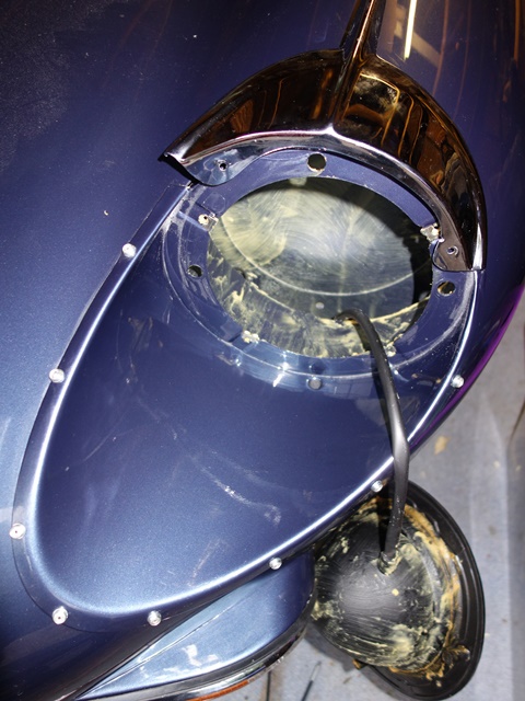
Again the rivets wouldn’t push through once the head had been drilled off. They felt as though they were embedding themselves into the lower panel.

The headlamp was subsequently re-attached using 2 spacers washers under the head AND a washer under the rear. This was to give the blind part of the rivet something firm to compress against so, fingers crossed, they’ll be easier to drill out in future!

The problem wasn’t the number of spacer washers but the shape of the beading trim. I’m certain they had been distorted during the re-chroming as polishing puts a fair amount of heat into quite thin material. It’s not easy to fettle their shape to fit once the chrome plating is on. They can be rotationally flexed but not re-bent to match the scoop contours.

The chrome beading fitted poorly with noticeable gaps caused by forcing the beading to clip onto some of the rivet heads. In fact the addition of two spacers made these gaps worse, allowing the rubber strip to move underneath. This time I’d spent a further weekend ‘not fitting a headlamp’! Rather disheartened, I’ve given up for now and will have another stab once my enthusiasm is restored!

At least one headlamp is in!

One they are completed, it will be a job I hope not to have to repeat and I’m now questioning the wisdom of the positioning of the inline fuses for the headlamp relay modification!

May 132014
 

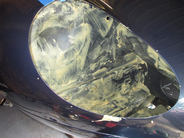
Fortunately it was possible to re-chrome the sidelight/indicators. However to do so ACF Howell had to remove the bulb holders and reflectors, neither of which faired out too well during the removal process.

The other problem was that one of the lens screws had sheared and I’d forgotten to remove the remaining section prior to sending everything to be re-chromed. So not only was it corroded in place but it was now sealed with a layer each of copper, nickel and chrome.

It was carefully drilled to break the plated layers and soaked in penetrating oil for weeks before attempting to remove it using a left handed drill bit. It wouldn’t budge so there was no alternative except to drill it out and re-tap.

Fine in theory but the lens screws are an odd size (approx. 0.130″ diameter and 32tpi). None of the local machine shops had a suitable tap and various internet searched failed to find one too. The closest tap was 6-32 at 0.136″ diameter which will now require a different size screw.

The next challenge was to find some new bulb holders which also proved to be very elusive. I finally managed to find some at the Stoneleigh spares day on a stall offering headlight re-silvering for very old classics.

The side lights require a bulb holder to fit a 5/8″ diameter hole while the indicator is for larger a 7/8″ hole. Once in place, the bulb holder edge is peened over to secure it in position.

The metal body of the light unit acts as the earth connection for the bulbs. A good earth would probably be achieved just by the four mounting screws, as the whole of the lower bonnet panel is earthed directly from the bonnet plug. However a brass bullet connector ring is also fitted to the indicator bulb holder and wired to the earth running in the loom.

Components for front lights Holder pressed in tightly Earth bullet connector

The indicator bulb holder is much harder to fit than the side light as the holder edge needs to be peened over tightly so the earth connector at the rear and the reflector inside aren’t wobbly. I rigged up a method of clamping the rear which took care of the earth connector. The reflector could then be held hard against the unit while a metal rod was tapped to peen over the edge of the holder. An additional pair of hands would have been very useful!

The disadvantage of someone else dismantling the units is not being able to recall what was removed. As a result, I’d overlooked the re-fitting of the internal shield. Fortunately it’s simply secured by two 2.4mm rivets and once in place, creates separate indicator and side lamp compartments.

Sprung bulb seats fitted Almost forgot the internal shield Shield riveted in place

I thought the rebuilding of the units would be fairly simple rather than the palaver it turned out to be to get replacement parts. It took three attempts to get the lens seating foam from SNG Barratt. Each time they were ordered I received the gasket for the side reflectors only found on US cars. Eventually we found out that my copy of their catalogue had a typo!

Fortunately the rubber boots fitted over the rear of the holders were in good condition as they’re not available any more. I also had to remake all the sprung bulb seat connectors as the wires were way too short.

Still that would be the least of my worries …. all the chrome units had been sent to Hutsons specifically so they could be trial fitted and the body work adjusted prior to painting. Both indicators were miles out and clearly hadn’t be fitted before the bodyshell was painted and the lights sent on to be re-chromed. Really not impressed.

It appears that the holes for the indicator units in new bonnet panels are approximate and need to be fettled quite extensively. I therefore had no alternative – I’d have to take a grinder to my painted bonnet to open out and reshape the hole. The accuracy of the bonnet panel is also amiss as I’m certain the indicator inserts haven’t been welded into the bonnet squarely.

The other odd thing is that only two of the four mounting points have nuts welded to the bonnet panel. Once the headlights are installed there won’t be access to the rear of the units. So I’ve had to fit some spire nuts in these holes.

The mounting holes in the indicator units also had to be enlarged to try to overcome the alignment problem. Even so, I’ve not been able to mount the units a horizontal as I would like. It’s something that will bug me now!

Complete unit ready for fitting Much fettling was needed to fit One down, one to go!
May 082014
 

The breakdown of the re-chroming quote received from ACF Howell simply had ‘RIP’ written in place of a cost for the rear light clusters …. and I had thought they looked in better shape than the front lights, which they were able to re-chrome! I was therefore slightly weary of picking up some second hand ones at the Stoneleigh spares day, just in case they too were later found to be beyond help.

The general view is that the aesthetics of the S2 suffered with the tightening of US health and safety regulations, by the introduction of the rear wrap-around bumper and rather slab rear-end look. They have a lot to answer for!!

Peter Crespin, an author on Jaguars, had ‘tidied’ up the rear of an S2 based around using the rear light clusters from a Lotus Elan 2+2. These have a reverse light incorporated into the unit thus removing the need for the separate reverse lights either side of the square number plate.

Rear of Standard S2 Rear using Elan rear lights
Images courtesy of E-Type forum

The number plate mount and aluminium number plate finisher are also dropped enabling the more traditional oblong number plate to be attached directly to the body. This in turn enables straight exhaust resonators to be used rather than the splayed ones introduced with the S2.

While I much prefer this uncluttered look, I still wanted to be able to revert to standard relatively easily/cheaply. The main expense is the rear light clusters so the decision was whether to buy the correct ones or the Elan 2+2 units. The problem would be that having separate reverse lights might obscure the ends of the number plate.

A quick call to Framptons confirmed that they would be able to produce an oblong number plate which would fit inside the original reverse lights (just!), because my registration number only had two digits and one of these was a ‘1’.

Decision made. I would stick with the correct light units and the reverse lights but would swap to an oblong number plate and straight exhaust resonators.

One of the rear housings for the light units had been pushed in and badly twisted. Presumably when it sustained the rear bumper damage. Fortunately I managed to find a pair of second hand ones although their hand-painted finish looked as though the previous owner had had a fight with the paint brush …. and lost!! Nothing some shot blasting couldn’t cure.

The replacement housings may well have been from another Jaguar model because they didn’t have the retaining nut on the rear face and new ones had to be welded in place. The paint had been masking some quite bad pitting, so the housings were left to soak in phosphoric acid for a while to convert any remaining traces of rust before being filled and painted with Epoxy Mastic 121, along with the final few unpainted parts.

I also decided to give the inside of the housings and the back of the light clusters a number of coats of Dinitrol hard wax in an attempt to delay the onset of the same corrosion problems in future. Several thick coats of Dinitrol were applied – initially it looks a mess but dries overnight to a thinner, more uniform finish.

The parts diagram indicates that there should also be a foam gasket (item 5) sealing the aperture where the lamp cables exit the rear housing. Despite numerous searches, I couldn’t find anyone who supplied them so I knocked up some gaskets using some Dynaliner. The foam is closed cell so shouldn’t absorb water which would making things worse rather than better.

First the light housing must be attached to the body. The inboard side with two 3/16″ setscrews, one securing the light’s earth connection, and the outboard side with two 3/16″ self tappers into a square nylon span-in nuts.

However I found that once the housings had been fitted, it wasn’t possible to fit the bolts securing the rear bumpers. Therefore these bolts need to be screwed in place beforehand.

The bumper brackets slide onto these bolt so it’s not necessary to fit the rear bumper first. Although access to the bolts starts to become limits once the light units have been mounted to the housings.

I’ve found Bresco very useful for supplying many of the odd trim fittings and they supply a pack of the Nylon snap-in nut for 17/64″ square hole (code 80200P), which is sufficient for the rear lights, the reverse lights, the padded door brackets and the brackets for the internal door lever operating the door locks.

Oddly the inner two bolt holes of the reproduction light clusters were tapped. This didn’t make sense to me as it would stop the bolts providing a clamping force on the clusters against the housing. Once the screw had engaged with the thread in both the light cluster and housing, they would move in unison along the screw thread and would not be drawn together.

In the end I gave up and drilled the bolt holes to remove the screw thread to obtain a good seal on the rubber gasket between the two.

Finally the reverse lights and number plate light were screwed in place to complete the rear lighting.

Jan 162014
 

There’s been a dramatic drop off in progress with the restoration in the last month or so. Partly due to the horrible winter weather, resulting in an apathy to venture out into a cold, dark garage!

In the meantime, attention has turned to sorting out bits and pieces that could be worked on indoors, although it gives an excuse for the gratuitous inclusion of some photos of the main reason for the lack of headway … a diving trip in warmer climes!

Progress is delayed due to a spot of diving …. with some immature 6m Whale Sharks

Back to the plot …..

Several years ago I’d come across an owner’s restoration of a ’63 OTS where they had redesigned the looms to their own specification, incorporating relays for the headlight circuits. The addition of relays made good sense, as they remove the main current bearing wires from behind the dash area, but I wasn’t convinced about having bespoke wiring looms made.

Deviating too far from the original wiring looms would mean that, if I subsequently encountered electrical problems, I’d be on my own as it would be hard seeking accurate advice from fellow owners. There was also the fear of overlooking a critical wire when the looms were made up or getting the length of one of the wires slightly wrong. It would be an expensive mistake to fix!

So the idea of adding relays was shelved and a new set of standard looms purchased. Fortunately this proved to be the right course of action. At the time, I hadn’t spotted the wiring diagrams I was using weren’t correct for my car. They didn’t have the changes in circuitry covering the introduction of the ballast resistor into the ignition circuit.

Rather timely, as I was starting to look at the lighting and bonnet electrics, an excellent write up of a headlamp relay modification was covered on the E-Type forum. The installation is very discreet with the relays being mounted out of sight behind the LHS ‘sugar scoop’. The only visible sign of the modification is the main power feed, taken from the alternator B+ terminal.

The downside of tucking the modifications within the bonnet is that it will be much trickier to maintain if something fails. The headlight bowls and possibly the indicators would need to be removed to gain access.

I had some spare repro 6RA relays so all I needed to purchase were some suitable coloured & rated wires and two in-line fuses. I also decided to install Halogen headlights at the same time.

The circuit diagram shows the planned wiring modifications, with the additional components labelled in red.

There are two spare terminals in the 8-pin bonnet plug, which were originally for the bonnet mounted horns found in the earlier cars and, I believe, the provision for optional extra spot/driving lights.

One of these spare terminals was used for the single high load wire running from the alternator B+ terminal to the 10-way connector in the bonnet. (It’s much easier to take a supply from the B+ post rather than travelling all the way back to the battery.)

I managed to feed the wire into the PVC sleeving to the bonnet plug so the only visible sign of the installation in the engine bay is a single sheathed wire running from the alternator to the bottom left of the picture frame, which has been cable tied to the existing loom.

From the bonnet connector, this feed splits in two to provide the 12v supplies to the dipped and the main beam relays. The relays have a double spaded terminal for the switched output, so the wires to the left and right hand lamps were connected directly to the relay.

Wire and fuse ratings
The Halogen dual filament bulbs are rated as 55W/65W at 12v so the dipped and main beams for each bulb will draw around 5.5 amps and 6.5 amps respectively (assuming a charging battery voltage of 14.3V).

Normally only one set of the filaments are on at any one time. However the worst case is when the main beam is ‘flashed’ while the dipped beams are on. Even though this should only be for short periods of time, I thought it prudent to assume the maximum current required for both headlamps would be 24 amps (2 dipped @ 5.5A each and 2 main beam @ 6.5A each).

Therefore 44/0.30 cable, rated at 25 amps, has been used for the supply from the alternator rather than the 28/0.30 cable suggested in the forum write up. Inline fuses have been used for the connections to the two relays. Their wiring is rated at 30 amps which is more than enough, although they have both been fitted with 15 amp fuses as the expected loads are 11 amps dipped and 13 amps main beam.

Using two fuses should ensure that a blown fuse won’t result in the complete loss of lighting!

The original wiring for the dipped beam (Blue/Red) and main beam (Blue/White) will now just be used to switch the relays. The coil resistance for the 6RA relays was measured at approximately 83 ohms so the switching wires will now only need to carry around 0.17 amps. Therefore the dash mounted fuses 1 & 2 have also been replaced, by 0.25 amp fuses.

As the whole bonnet area had been coated in copious amounts of Waxoyl, I also fitted some PVC sheathing to the bonnet loom in an attempt to keep it clean. I just need to tidy up the cabling when the headlamps are fitted.

Dec 092013
 

As with many other cars of the period, E-Types use Lucas 6RA relays to control the power supply to the various electrical ancillaries, specifically those that draw larger currents. The obvious benefit of using a relay, an electrically operated switch, is it allows a high current circuit to be controlled by an isolated, low current circuit.

This enables all the wiring handling the highest currents to be located within the engine bay and controlled by low current wiring routed from the dash area. Removing the high current wiring from the dash reduces the potential fire hazard.

So it’s odd why Jaguar didn’t use relays to control the main and dipped headlights. The addition of headlight relays is another popular modification which I’ll be making in due course. The mounting of the horns was relocated from within the bonnet to the picture frame during the production run of the S1 4.2. This has freed up a connection in the 8-pin bonnet plug which can now be used for the high current feed from the battery and the relays can be discreetly located behind the headlamp sugar scoop.

Four types of 6RA relays are used in the later S2 cars (those with the ballast resistor):
Terminals layout for the Lucas 6RA relays - applying 12volts to the W1/2 terminals switches the relay, connecting the C terminals

  • Alternator Relay – 33209F (SRB121) : 20A 4 pin
  • Starter Solenoid Relay – 33231E (SRB400) : double contact 5 pin
  • Cooling Fan Relay – 33232E (SRB501) : 3 pin
  • Horn Relay – 33252E (SRB111) : 20A 4 pin

Note: the SRB numbers are the modern replacement product codes

Internal wiring layouts for the Lucas 6RA relays
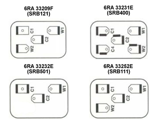
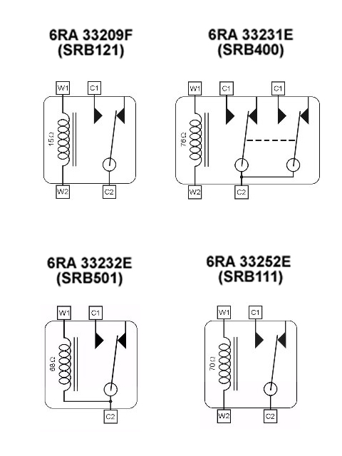
To the right are diagrams detailing the external terminals and internal wiring for the four 6RA relays used in the S2.

The difference compared to the earlier cars is the starter solenoid relay has double contacts to enable it to provide power to the starter solenoid as well as bypassing the ballast resistor while the starter is in operation. All are simple electromagnetic type relays, which are ‘normally open’.

The various relays were all working fine but were showing the effects of decades of exposure to the elements and looked very scruffy against all the restored components.

The relay covers are only crimped in four places so it was possible to carefully undo them to enable the covers to be removed. These were dipped in a mild citric acid solution overnight to remove the remains of the zinc plating before being re-plated.

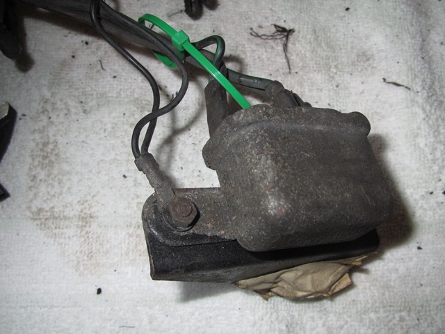
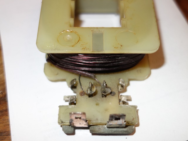
With the exception of the 3-pin cooling fan relay, the W1 and W2 terminals are used to energise a coil winding which has an iron core at its centre.

In the energised state the coil produces a magnetic field which draws a sprung, iron armature towards the iron core. In doing so a contact at the end of the armature (C2 terminal) makes a connection with a fixed contact, the C1 terminal or the C1 & C4 terminals for the double contact relay.

The 3-pin relay lacks a W2 terminal because it is designed for applications where terminal C2 is always connected to 12 volts. Internally the C2 terminal is also connected to the coil winding and so acts as the W2 terminal as well, delivering 12 volts. The coil winding is therefore energised by grounding terminal W1, resulting in the switching of the relay.

All that remained was to tidy up the electrical connections and re-crimp the covers back in place.

Ignition Switch
As I was sorting out electrical bits and pieces, attention turned to the Lucas ignition switch, which is marked 157SA 39415A. I’m not sure if this has been replaced at some stage but the terminals bore no correlation to the wiring diagrams and had intermittent connections when tested with a multi-meter.

The terminal connections on the wiring diagrams indicate:

  • 1 – Brown : supply from Battery, under permanent current
  • 2 – White : under tension only after ignition switch is on
  • 3 – White/Yellow : via starter solenoid relay, delivers power to the starter motor

Therefore, when the key is in position II, terminals 1 and 2 should be connected and when the key is in position III, terminals 1, 2 and 3 should all be connected.

To achieve this with my 157SA switch, the White/Yellow wire can only be connected to terminal 1. The other wires using terminals 2 and 3, in any order. I decided to take the switch apart to see if it was possible to ‘correct’ the terminal connectivity and address the intermittent connection problems.

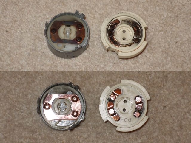
The switch can be split in half by gently prising the retaining tabs outwards. The tabs are made of pot metal so I wasn’t sure they would survive the operation.

Inside the copper contacts were heavily ‘gunked’, which was the most likely cause of the intermittent connections, so they were cleaned up with good old Brasso.

The key lock engages with a nylon disc within the switch, which therefore rotates as the key is turned. On the underside of the disc is a sprung ball bearing which locates in dimples to differentiate the key positions and a spring which returns the key position from III (starter motor engaged) to position II when the key is released.

There’s no ability to change the terminal connectivity so I’ll just have to adjust the terminal wiring accordingly.

Nov 122013
 

The horns suffer a harsher environment that a lot of the other component as they're located low down at the frontA pair of Lucas windtone 9H horns was fitted to the Series 2 E-Type, one emitting a high tone and the other the low tone. The excitation of the air column is achieved by vibrating an internal metal diaphragm, with the frequency of vibration and the shape of the horn snail or trumpet determining the note produced.

The switching frequencies are carefully chosen to produce a major third musical interval (spanning 4 semi-tones). Together they set up beat frequencies producing a tremolo affect and a perceptibly louder sound. In the case of the 9H, the low tone switches at 392Hz and the high tone around 494Hz, producing a G and B respectively.

Great in theory, however both my horns were stamped with an ‘H’ on inside of the trumpet indicating they both produce the high tone. Well, they would, if they both worked! One of them only produced a sound for a split second before falling silent. The only recommended external adjustment that can be made is the contact breaker gap via a small screw.

The horns were shot blasted (after blocking up the inner trumpet!) but only the working horn could be painted at this stage
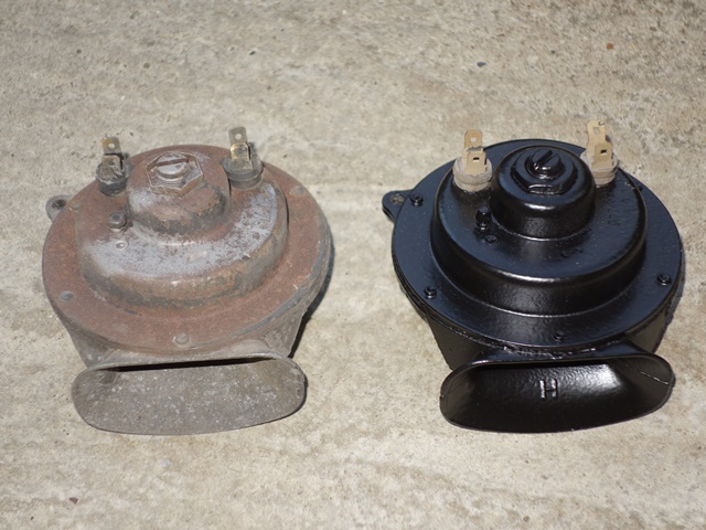
Rather optimistically I thought it would be just a matter of readjusting the gap to get it working again. Alas, there was something more seriously wrong inside so only the good one was repainted at this stage.

One of the problems with the horns is the two halves are press riveted together. I’ve not been able to find anyone who supplies these rivets so, even if a repair is possible, it won’t be an ‘invisible’ repair.

I’m thinking of using something like Chicago screws but first I need to get inside to find out how it works and if it’s possible to change the frequency. It’s a voyage of discovery from here as I’ve not found any information on the horn innards.

The rivets were drilled and then punched out – the rivet inside the trumpet is slightly shorter than the others so I’ll have to remember that when ordering fixings to hold it back together. The two halves can then be carefully separated as the diaphragm was sandwiched between two thin, wax impregnated gaskets which are quite fragile.

Drilling out the rivets Horn carefully split in two Metal diaphragm removed

The rivets had to be drilled and then punched out to split the horn

The horn split in two - the right hand side has no moving parts and is just the horn snail or trumpet

The diaphragm removed, showing its ferrous attachment and disc operating to operate the contact points

The diaphragm was then removed to reveal the inner workings. Attached to the centre of the diaphragm is a ferrous cylinder so that its movement can be controlled by the rapid switching on and off of an electromagnet.

When current is applied, the ferrous cylinder and therefore the diaphragm is drawn towards the electromagnet. As the diaphragm nears the end of its travel, a disc around the ferrous cylinder hits the base plate of the contact breaker, opening the points. The electromagnetic field then collapses and the diaphragm returns to its natural position and the process is repeated.

Operating the base plate of the contact breaker to open the point. The points were cleaned with some 400 grit wet and dry paper
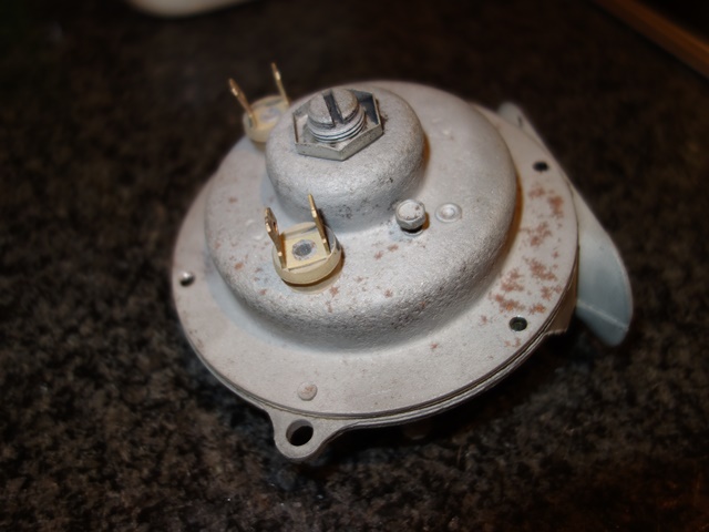
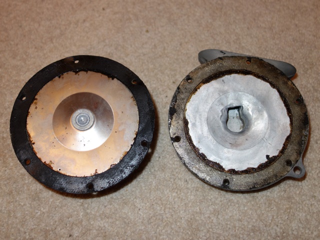
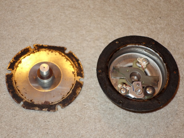
The resistance of the contact points was around 7 ohms so a light rubbing with 400 grit wet and dry soon got this down to 0.8. Although I wouldn’t have thought this would stop the horn operating. I think the problem is with an external screw fitting which the service manual suggests should not be touched.

I’m fairly sure it has been adjusted at some stage as it’s screwed tight against the ferrous attachment. Therefore stopping any possible movement in the diaphragm.

Of the two external adjustments, the small screw adjusts the contact points gaps. The service manual states that this does not adjust the tone and is only to take up wear in the points. The central screw adjustment, with locking nut, only limits the length of travel permitted by the diaphragm so if it did effect the tone it would only be marginal (ie for fine tuning). I doubt it would give anywhere near the variation to recalibrate it to the low-tone.

Hmmmm …. stumped. Going back to first principles, due to the lack of tone adjustment in the electric components. The tone must be controlled mechanically but the spring rate of the diaphragm is fixed. Therefore the only two things that I can see that would effect the output tone are the mass of the ferrous diaphragm attachment, which would naturally impact the switching frequency, and the shape of the trumpet.

Neither of these two can be changed (easily) with the parts I have in front of me! I’ve found a restorer of old horns, Taff The Horns, who might have a non-working low-tone horn to provide a donor for a transplant. Otherwise plan B is to purchase a repro horn from Holdens for about £40!

A whole post on horns without a reference to a sketch by the late Peter Cook!!

 Posted by at 8:02 pm  Tagged with:
Apr 122013
 

The separate wiring loom for the starter solenoid relay was sent off to Autosparks so they could have a look and use it as a pattern to make up a new loom.

In the meantime, I’d posted my wiring dilemma on the E-Type forum to see if others could shed light on the relay wiring. A fellow S2 owner kindly pointed out that there was a change to this area of the wiring during the S2 production run. As it happens, at exactly the same time my car was passing through the factory. I guess that it hadn’t been reflected in the service manuals because the modification had been made mid-production run.

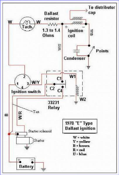
Around the end of ’69, a ballast resistor was introduced into the ignition circuit with the aim of improving cold starting. The original 3 ohm coil was replaced by a ballast resistor and coil wired in series, both being around 1.5 ohms. When the ignition switch is turned to start the engine, the starter relay activates, delivering power to the starter solenoid but also bypassing the ballast resistor.

Therefore when starting, the full 12 volts is applied to the coil. The spark energy is increased over the original setup as the current flowing into the coil is greater due to the lower coil resistance.

Once running, the ballast resistor is introduced back into the circuit. As the coil and ballast resistor have a similar impedance of around 1.5 ohms, the voltage drop across each is roughly the same. Therefore a voltage of 6v is applied to the coil during normal running.

I found the wiring diagram above on one of the American Jaguar sites which shows the wiring connections for ballasted cars. Autosparks also confirmed that they stock this ‘ballast resistor’ loom. Although I think I’ll get the car running before I cut and tape the unused wires in the main loom!

It was a good opportunity to get Autosparks to make up the additional wiring, using the correct colour coding, that I needed for the few upgrades I’d planned – the mechanical brake light switch to supplement the hydraulic switch and the boot light.

There was also a number of wires that I believe are missing from the sundries wiring pack, such as earthing wires for the rear light clusters and a beefier jumper wire between the two brown fuses. Touch wood, I’ve now got everything to complete the wiring.

Alas, it was again a case of one step forward and two back. Very early on in the work on the bodyshell, the LH outer pedal side panel had been replaced where the main loom comes out behind the voltage regulator bracket. The panel was from one of the main suppliers of panels so I foolishly assumed it would be spot on.

It was only once I came to fit the voltage regulator bracket that I found out that its mounting holes had been punched in the wrong place. They were about 5-6mm too close to the sill closing panel so that the bracket doesn’t fit. The bracket did change for the S2 cars so it might be that the panel also changed and I was supplied the wrong part.

Either way – not happy! I should have checked it well before it had reached the paint shop. It’s not the end of the world but it will always niggle me as I’ll know it’s not correct on the car. The annoying thing was I’d spent ages sourcing and refurbishing a replacement bracket, as the studs on the original had all sheared trying to remove it.

The first replacement was purchased from SNG but the fitting was incorrect, using bolts rather than attached studs. Some time later, I managed to get a rather tatty one on eBay which was covered in a mixture of black and green paint. It took several applications of Nitromors and wire brushing before it was good enough to be re-plated.

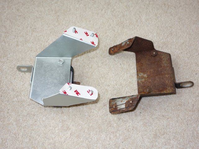
The problem I find with zinc plating is it’s too blingy (although I’m sure the brightness would dull slightly once exposed to the elements). I decided to experiment and sprayed it with a two-pack clear satin lacquer. The results were even better than I had hoped/expected. The satin finish obviously tones down the brightness but it also has a softer, smoother to the touch feel and a more uniform metallic finish.

After all that effort I didn’t really want to start butchering a perfectly good original part to fit. instead I planned to trim the original bracket to fit and then repair the welded studs but SNG Barratt now supply the brackets with the correct studs relatively cheaply. So I’ll adapt one of their repro parts rather than an original part.

I think I’ll also spray most of the plated parts in the engine bay with the clear satin lacquer. Hopefully it will also provide a more durable finish.

Apr 012013
 

As I’d spent many days meticulously labelling the new wiring looms using both the service manual and Coventry Auto Components diagrams and all the connections were accounted for, I foolishly assumed everything was correct. All that would remain would be to connect up the looms to each other and the corresponding components.

However I hadn’t checked back to the original loom … until now. The two looms are completely different for the connections to the starter solenoid relay, mounted on the engine bay bulkhead.

The relay connections on the new loom end close to the join between the dash loom and the RHS body loom, circled in Red in the photo. The ends are terminated with female spade connectors suggesting the relay is attached at this point.

However 1) there’s not sufficient length to route into the engine bay and 2) there’s no suitable exit hole near the relay into the engine bay.

So I can’t see how to route the new loom to the relay mounted on the bulkhead.

Where the new loom ends with the relay connectors, the original loom has both the larger current carrying wires for the relay (White/Red and Brown) wires cut, only the switching White/Yellow wire remains. The other end of the brown wire exiting the loom near the ignition switch is similarly cut. As both cut ends appear to be properly taped it could quite possibly be a factory modification, made retrospectively to looms that had already been delivered to Jaguar.

Current carrying wires cut

Brown ignition wire cut

I’ve not located the other end of the White/Red wire yet due to a slight mishap with a Stanley knife while cutting away the taping on the old loom. I’ve found the braided wires to be quite absorbent and the claret colour of blood does a splendid job at hiding the colour coding! Lesson re-learnt: cut away from fleshy bits, not towards!

The relay was connected via its own separate loom, which also appears to be original (right). The routing of the White/Red and Brown wires, cut in the original dash loom, is directly between the bulkhead relay and the starter motor, ie doesn’t enter the dash area.

The switching White/Yellow wire is contained in a spur with sufficient length to reach the dash area from the engine bay via the hole high in the transmission tunnel panel.

So my current thinking is that this was a factory modification to keep the current carrying wiring away from the dash. Only the relay switching wire carrying a low current is routed into the cabin area.

I suspect this change may have been made during the S2 production run as I’ve not found any of the usual suppliers who sell a separate starter solenoid relay loom. I will have to ask Autosparks to make up a loom based on what remains of the original. The other issue is the original loom had a White/Blue wire connected to a central terminal on the relay. There’s no reference to a White/Blue wire in any of the wiring diagrams so I’m stumped what it is for at this stage.

I’ve subsequently found out that it was a factory modification after all. From chassis number 1R1393, just 28 cars before mine, a ballast resistor was introduced and the relay moved to the engine bay bulkhead.

The starter relay was changed so that it could switch two circuits – delivering power to the starter solenoid and bypassing the ballast resistor. The white/blue wire enable the ballast resistor to be excluded from the circuit on start up, increasing the current delivered to the coil.