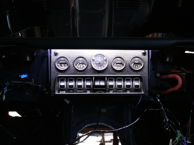
The backlighting of the dash gauges is provided by incandescent bulbs inserted into the rear of the gauges and is fairly poor by modern standards. The green hue of the backlighting is achieved by coloured plastic covers within the gauges and green plastic tape behind the switch legend strip. However the heat produced by the bulbs had melted several of the covers.
The backlighting can also be set to Bright, Dim or Off via the 3-way Panel Switch. The light produced by these bulbs is almost linear to the applied voltage. When bright is selected, 12 volts is applied across the bulb terminals. While switching to Dim introduces a resistor in series with the bulb. This produces a voltage drop across the resistor and therefore the voltage applied to the bulb and the emitted light is reduced.
 One popular ‘upgrade’ is to replace the bulbs by LED strips mounted around the perimeter of the inside of the gauges. LED strips are available either containing a single LED colour group (eg white, red, green, blue, yellow) or all three of the additive primary colours; red, green and blue.
The latter, for obvious reasons referred to as RGB LED strips, can output different light colours by adjusting the relative intensity of each LED colour group. The LED strips also have the advantage that they are more efficient and do not generate a large amount of heat.
The upgrade is well documented in Stéphane’s guide on the E-Type forum. One of the members had tried the upgrade with blue LEDs and I thought this would suit my car, being Opalescent Dark Blue, but I was undecided whether I wanted to lose the original green.
I couldn’t decide which I preferred so I investigated the possibility of being able to switch between the two. In the end I decided to use the RGB LED strips and somehow try to use the spare dash switch (used for the heated rear window on the FHC) to toggle between green and blue. This would lead to numerous problems that would only become apparent as work progressed.
The LED strips currently on offer vary in the number of LEDs per metre; typically 15, 30 or 60 LEDs per metre but also in the strip width; either 8mm (3528 chipset) or 10mm (5050 chipset) and with or without waterproof covering. The aim was to increase the brightness of the backlighting but with the constraint of space within the gauges. So I thought the thinner strips with the waterproof option would be sensible, so I ordered the following:
- 2 metres (min order) of 3528 Pure White 60 LEDs/m – for the dash map light
- 5 metres of 3528 RGB 60 LEDs/m – for the gauges
The strips with 60 LEDs per metre can be cut every three LEDs, ie every 5cm. This was ideal as the inner circumference of the smaller gauges would allow a 10cm strip. However the first problem came to light, excuse the pun, when I tested the 3528 RGB strip. This chipset used has one LED for each of the three primary colours in a 5cm strip. When either blue or green is selected, only one of the three LEDs was illuminated. So in the 10cm strip possible, lighting would only be provided by two LEDs – hardly an improvement!
After a few calls to suppliers, it became clear that I needed the wider 10mm strips for the multi-colour option. Each LED in the 5050 chipset is effectively made up of three LEDS; one for each of the red, green and blue colours. So all six LEDs in the 10cm strip would provide light. If the additional width caused a problem I would give up on being able to switch colours and revert back to a single coloured 8mm strip.
While I was planning how to incorporate the upgrade into the existing switch layout I noticed something really odd in the wiring diagrams which I couldn’t understand. The power for the dash illumination is only provided when either the side or main headlights are on. This made perfect sense – if it’s dark enough to need lights then you’d always want to illuminate the gauges. So why did the Panel switch have three settings: Bright, Dim and Off? Why on earth would you ever want to have the side/head lights on and not the dash?
I started to doubt the wiring diagram and so posted the question on the forum. Apparently in the 60s it was a legal requirement when parking at night to have the side lights on. In which case the dash illumination was turned off to conserve the battery. I don’t think I’ll ever need his feature so I’m considering swapping to a two state Panel switch – Bright and Dim.
With the planning done, the next step was to start to dismantle the gauges ….


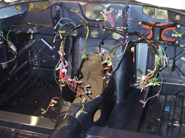


 Somehow the old loom had turned itself into a right old bird’s nest while in storage. It took quite a while to untangle it so that it could be laid out, mimicking how it is routed within the car. Armed with a multi-meter and the wiring diagrams, I set about the simple task of labelling the new looms …
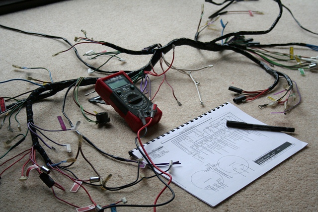 Other issues that, for now, remain unresolved are i) a missing green & brown wire for the reverse light switch and ii) a spare purple & white wire at the centre of the dash. The E-Type forum is very helpful in cases like this as there’s a wealth of knowledge available from the forum members. I was not alone with both the missing and extra wires as one member had decided to use the spare purple & white wire for the reverse light switch. Perhaps I’ll need to do the same.