
The green illumination of the dash gauges is achieved by plastic green filters within the gauges. However almost all of these filters had deteriorated due to their proximity to the incandescent bulbs. Some had actually melted due to the heat produced. I had therefore decided to ‘upgrade’ to LEDs after reading the conversion on the E-Type forum. For my conversion, I wanted to:
- Retain having two brightness settings: Bright and Dim *
- Switch between green and blue lighting
* – I couldn’t envisage a situation when I would want the side/head lights on but the dash not illuminated. So I have decided to drop the ability to turn off the dash illumination and have replaced the 3-way Panel switch with a 2-way switch.
Dimming the LEDs
 The RGB LED strips have a common 12 volt supply and then one wire for each of the primary colours. The LEDs for a specific colour are turned on by connecting the corresponding wire to 0v, ie earth.
The amount of light produced by incandescent bulbs is linear to the current flowing through the bulb. Therefore accurate dimming of the bulbs is achieved by switching a suitably sized resistor into the circuit, in series with the bulbs.
Unfortunately this task is not as simple with LEDs. The light output for two ‘identical’ LEDs is not as predictable simply by reducing the voltage drop across them. The only reliable way to dim LEDs is rapidly switching the LED on and off. Above a certain switching frequency, the human brain cannot differentiate between when the LED is on and off. The perceived brightness is then the relative percentage of time the LED is on during one switching cycle.
 Fortunately it’s possible to purchase small LED control units to perform this function. My initial trials using LEDs found that, without on/off switching, the light output was too great. Therefore two LED control units would be needed to control the brightness for both the Bright and Dim settings.
The other key difference, already mentioned, is that the 12v supply voltage is always connected. The individual LED colours are turned on by connecting their earth lead to a ‘floating earth’.
Note: this ‘earth’ is different from the car earth as when in dimming mode it will switch between 0v and 12v.
Green/Blue switching
 The ability to switch between green and blue lighting would require the complete rewiring of:
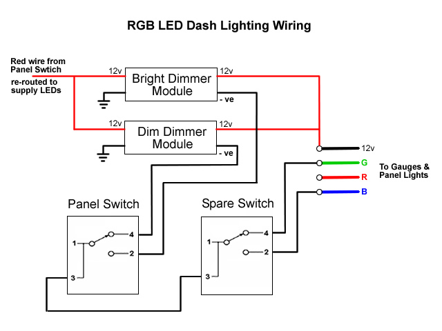
i) the panel switch to select either the ‘Bright’ or ‘Dim’ earth connection from the respective LED control module (rather than provide the 12 volt supply)
ii) the spare switch to then connect the selected earth to either the green or blue lead. After a few trials, I settled on the wiring diagram shown.
Both LED control modules are connected to the loom’s Red supply wire from Fuse 5, which is disconnected from the Panel Switch, and the car’s earth. The positive LED outputs from both control modules provide the 12v supply to the RGB cable.
New wiring is then needed to between the two switches for the earth connections to either the Blue or Green LED lead. Finally the gauges and switch legend LED strip are daisy chained together with 4-core RGB cabling.
Switch Legend Strip
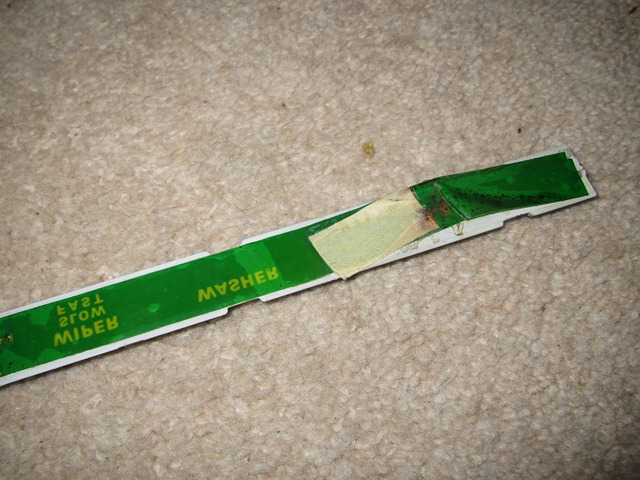
The switch legend is normally lit by three bulbs mounted in convex reflectors approximately 10cm in length. The green hue was achieved by a plastic green tape glued to the rear of the legend strip. However this has faded so it was now more of a mucky yellow colour. The tape was removed as the colour would now be provided by the LEDs.
| Green tape provided legend colouring | LED strips fitted to legend reflectors |
|---|---|
 |
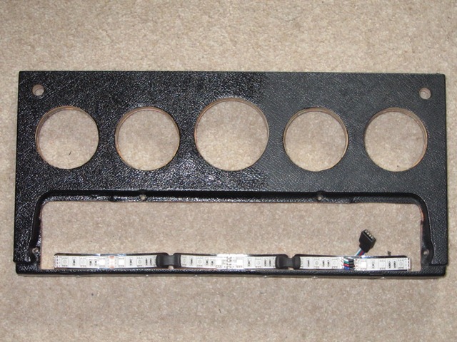 |
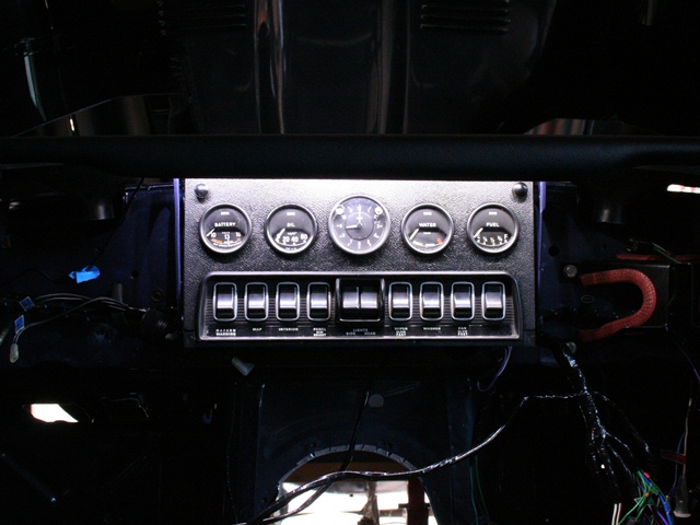
{Note: the dash photo was taken midway through being cleaned/treated with Gtechniq Trim Restorer C4 – hence the half and half look!}
Dash Gauges
The seven gauges are all opened by rotating the rim until tabs on the rim align with cut-outs in the housing. This enables the rim and glass to be removed to install the LED strips.
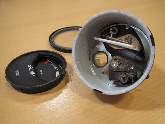
The internals of the smaller four gauges (water temperature, oil pressure, fuel and battery) are very similar where the mechanisms are permanently secured to the housing. These mechanisms are quite delicate so the dismantling and insertion of the 10cm LED strips needed to be done with some care.
These gauges have a face plate which has to be eased away from the underlying cup, which has the gauge’s scale printed on it. A small screwdriver can then be inserted under the rim of the cup to prise it away from the housing. Once loose, it’s a matter of rotating the cup to clear the fragile needle.
| Six dash gauges and clock | Face plate & cup removed | LED strip inserted from the rear |
|---|---|---|
 |
 |
 |
It’s very easy to inadvertently solder the RGB earth contacts together so it was well worth testing the operation of the LEDs before rebuilding the gauges.
 |
 |
 |
The clock proved to be more difficult even though the entire clock mechanism comes out with the face. It’s slightly larger than the other gauges and so can accommodate a 15cm strip. However the clearance between the housing and the clock mechanism wasn’t sufficient due to the clear, waterproof coating. This had to be peel off to fit.
| Removing the waterproofing | Cabling was a tight squeeze | Comparing brightness of colours |
|---|---|---|
 |
 |
 |
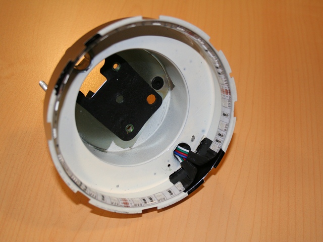
The entire mechanisms for rev counter and speedometer are also removed with the gauge face, which allows unhindered access to stick the 35cm strip to the perimeter.
| Rev counter housing | Cable pass through bulb opening | Testing prior to rebuilding |
|---|---|---|
 |
 |
 |
The downside of having the ability to switch between the two colours is it requires multi-core cable and so the installation is not so discreet. Even so, it will all be hidden from view once in place.
My first attempt was to use standard RBG cables and connectors but these provide to be temperamental and unlikely to stand the test of time. I therefore changed them to larger plug and socket terminals with internal, mini spade connectors which were also held together by a clip.
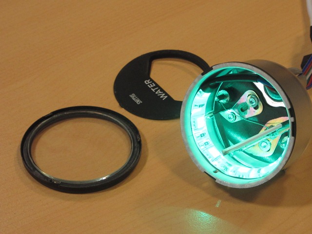
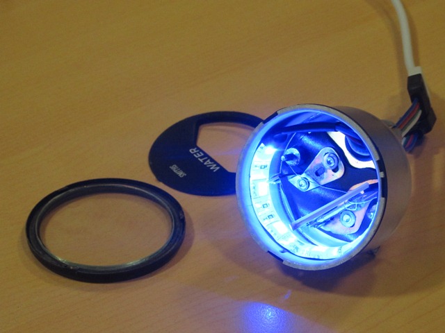
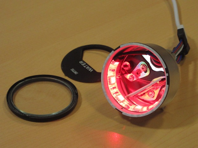
| RGB connectors were unreliable | Blue illumination without dimming | Switched to green illumination |
|---|---|---|
 |
 |
 |
The other LED lighting was to illuminated the boot when the bootlid was opened. Two 25cm pure white LED strips were stuck to the underside of the tonneau top panel. Power was provided by running a wire from the permanent Brown fuse terminals and switched by a micro switch attached to the boot hinge.
Would I do the same upgrade again? Definitely not! Possibly just installing a single colour LED strip but the ability to switch between green and blue lighting resulted in unnecessary complexity. Just because it can be done, doesn’t mean it should be done!


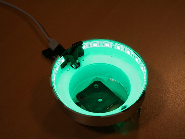
 One popular ‘upgrade’ is to replace the bulbs by LED strips mounted around the perimeter of the inside of the gauges. LED strips are available either containing a single LED colour group (eg white, red, green, blue, yellow) or all three of the additive primary colours; red, green and blue.