Jan 202014
 

It was frustrating to have gone through the process of re-plating/re-chroming all the individual components and to have rebuilt the handbrake, only to find that the ratchet had been butchered to fit an incorrect cable. Rather dispirited, I decided to keep the rebuilt handbrake as is and reuse the offending cable.

I’d hoped that it would be possible to rig up an alternative method of mounting the handbrake switch. However I wasn’t able to come up with a solution that I was happy with. Plus I’d found a number of forum postings of issues setting up the handbrake mechanism even with the correct, unmolested parts.

Old & New Clevises Correct cable is shorter

The existing cable was either incorrect for the car or a poor reproduction part. Both of its clevises were far too long, resulting in an inner cable length that was over 1/2″ too long.

I’m fairly sure that a previous owner/garage had relocated the cable abutment on the ratchet about 1″ rearward as a bodge to compensate for the oversized clevis.

The knock-on effect is the distance between the outer cable abutment on the ratchet and that at the handbrake compensator mechanism on the IRS has been reduced by the same amount. Squeezing the outer cable into this shorter distance effectively reduces the overall inner cable length by 1″ – so a net shortening of approx. 1/2″.

The handbrake compensator offers some adjustment to cater for stretching of the cable over time. Even so, 1/2″ would almost certainly put it at the limit of its adjustability. I’d probably be on a losing wicket trying to get it to work correctly. It was better to bite the bullet now rather than later. So a correct cable was obtained from the Jaguar Enthusiast Club, who now offered them via their online shop.

RM & J Smith were able to supply new ratchets which came as a relief, so it wasn’t necessary to buy a complete new handbrake. The only obvious difference is the pivot bolt spacers are welded to the replacement ratchets.

The fitting of the new ratchet was a simple task but the completion of the handbrake was foiled yet again. The bore of the outer cable abutment was 1/32″ smaller than the 3/8″ cable diameter. It has a slot machined into its circumference and is designed to allow a slight expansion, so I didn’t think anything was amiss.

The bolt securing the switch bracket then clamps the abutment onto the outer cable.

The only way I could get the outer cable into the hole was by continually twisting and pushing it. It didn’t feel right the more I progressed. Considerable effort had been needed just to get the cable half way home. So I decided to remove it and have a re-think. It might be possible to re-drill the bore although I was concerned the slot might cause problems.

I needn’t have worried. As soon as the cable was twisted in the reverse direction, disaster struck …. one half of the abutment fitting snapped clean off.

Aaaaargh and much cursing of repro parts!! Another case of what I now refer to as the Restoration March …. 1 step forward, several back!!

Looking at the fracture, it appears that the whole ratchet is hardened during the manufacturing process, presumably to provide the necessary hardness in the ratchet teeth. The downside, as I found out, is it makes the part brittle and prone to stress fractures. Not ideal for clamping parts which need a degree of ductility, such as the cable abutment.

RM & J Smith have been an excellent source of difficult to find parts and, to their credit, were very good, offering to send out a replacement immediately free of charge. They had identified the problem with the size of the hole and returned the ratchets to their manufacturer to be corrected. I had received one that slipped through the net. The following day the replacement arrived and it fits perfectly.

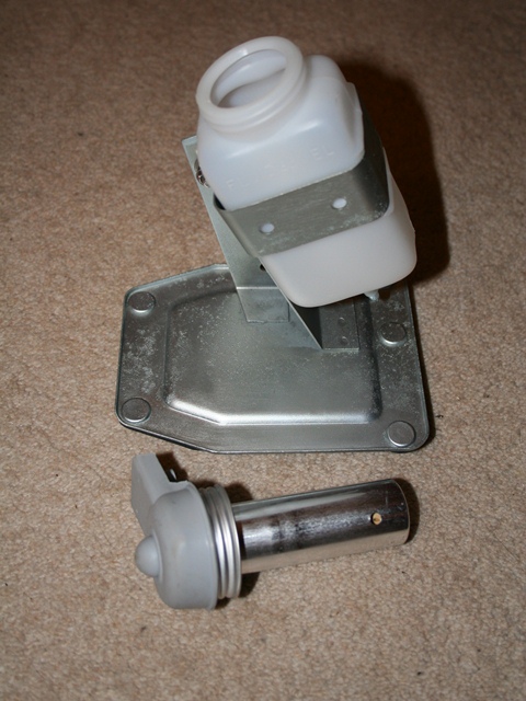
Getting the warning light switch properly set up proved to be much trickier than I’d anticipated and quite frustrating. The switch is activated by a ‘S’ shaped spring striker. When the handbrake is fully released the protrusion at the base of the lever presses against the striker, which in turn depresses the switch.

The main problem was mounting everything far enough forward so there was sufficient pressure on the striker to operate the switch.

Both the switch and striker are mounted to the bracket by two locking half nuts. So there is very little fore and aft adjustment that can be made. Mounting the switch progressively nearer to the striker starts to pre-engage the switches’ plunger, making the switching more hairpin-like until ultimately it’s permanently on.

I finally got it set up and working on the bench although I still wasn’t 100% happy. The switch had to be angled slightly and the warning light would be on as soon as the lever was moved off the end tooth of the ratchet. The plan was to mount the pre-built handbrake and switch but much to my dismay, I’d completely missed that fact that the cable has to be fed forward into the cabin through a guide bracket in the transmission tunnel.

All the set up was then lost, as the handbrake switch needed to be removed to free the cable. In situ, it wasn’t possible to reproduce as good a set up as before because the floor pan was stopping the angling of the switch. I found the best fit to mount the ‘S’ shaped striker horizontally.

I’m tempted to add some packing washers between the striker and bracket to allow the switch to be moved forward slightly. I think I’m going to leave the fitting the central console until after its first MOT so I’ll still have access to the handbrake.

Handbrake rebuild

 Brakes  Comments Off on Handbrake rebuild
Sep 022013
 

The re-plated handbrake component ready for assembly
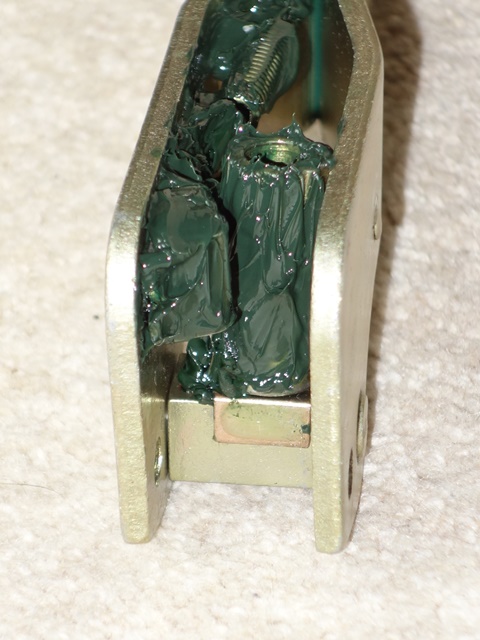
The handbrake had been sent off to ACF Howells for re-chroming as a complete unit. With hindsight it would probably have been better to dismantle it myself and just send them the pieces that needed re-chroming.

I therefore had to work out how the pieces should go back together. The original fittings for the handbrake light switch were missing from the car so the replacement parts would also be added to the puzzle.

Fortunately most of it is fairly self-explanatory. The only issue was having to cut down a roll pin to replace the retaining pin for the push button which wasn’t in the parts returned after re-chroming.

The first task is to reunite the push button operating rod and the pawl of the ratchet mechanism within the handbrake arm. The operating rod is fed through the access hole at the rear of the arm and the pawl is inserted up through the base of the arm, complete with its distance tube and a spacer either side.

Orientation of the operating rod & pawl A clevis pin connects the rod & pawl

The pawl needs to be orientated with the hole for the clevis pin rearward so the hole and fork end of the rod can be manoeuvred to protrude through the access hole in the arm. The clevis pin can then be inserted and secured with the split pin.

The push button needs to be fitted before the pawl pivot bolt, otherwise there’s not enough clearence to insert the retaining pin. Without the bolt, the operating rod can be pushed down the handbrake arm until the hole for the retaining pin is clear of the handbrake arm.

At rest the pawl is held in the locking position by a spring which is inserted onto the operating rod before the push button is fitted. The order of fitting is a washer (not shown in the photo) which sits against protrusions inside the handbrake arm, the spring, a retaining washer and then the push button.

Sprung push button components Roll pin inserted to secure button
The operating rod needs to pushed so it protrudes beyond the end of the handbrake arm (further than in the photo!) so the retaining pin can be inserted Copious amounts of grease was applied before the roll pon was hammered home

A forum member had a thin rubber washer between the second washer and the button. As a rubber washer wasn’t in the returned parts, I can’t be sure if my handbrake originally had one. When the button is fitted the spring is already under compression, providing a cushioning effect and wear isn’t an issue. Therefore I didn’t feel the need to fabricate a rubber washer.

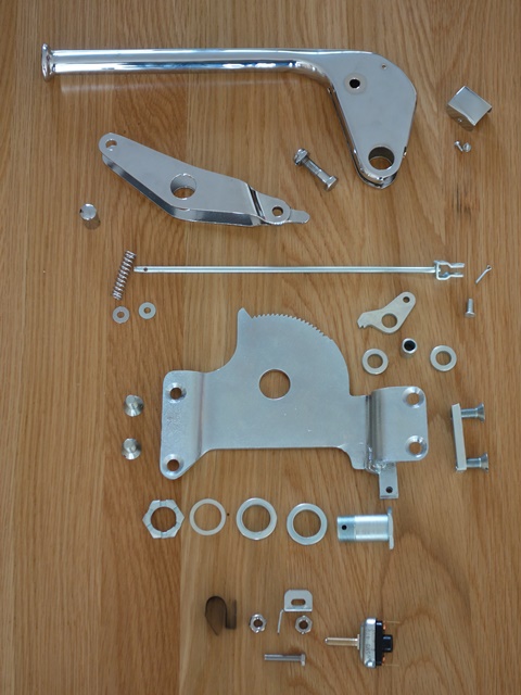
Next the ratchet gear needs to be inserted into base of the handbrake arm followed by fitting the outer cable attachment bracket. Similar to the pawl, the ratchet gear uses two spacers to fill the internal space within the handbrake arm.

The two bolts securing the outer bracket can then be fitted. One acts as the pivot point for the pawl and the other as the pivot for handbrake arm in relation to the ratchet gear.

The final piece in the puzzle was the fitting of the handbrake warning light switch. As mentioned, these parts were missing and so replacement parts were ordered from SNG Barratt.

It looked fairly obvious how things went together. A bracket mounts the switch to the base of the handbrake ratchet gear and it appears that a ‘S’ shaped spring attaches to the end of the switch.

When the handbrake is fully released, a ‘finger’ protrusion at the bottom of the outer cable attachment bracket presses against the spring, which in turn depresses the Push-to-Break switch.

The parts manual indicates two nuts are needed to secure both the spring and the switch. I’m obviously missing something as I can only see how to get it to work using three nuts – one to secure the switch to the bracket and two half nuts to lock the spring at the correct distance from the activating ‘finger’.

Handbrake caliper rebuild

 Brakes, Rolling Chassis  Comments Off on Handbrake caliper rebuild
Jul 032013
 

Now the handbrake calipers have had been painted, all that remained was to rebuild them …. for the second time!

The service manual suggests the two rear calipers and handbrake mechanisms should be removed as single units. However this needs the half-shaft inner joints to be broken and the front springs/shock absorbers to be removed, which seemed unnecessary.

The components for the handbrake calipers and self-adjusting mechanism ready to be re-built

I found it much simpler to detach the handbrake mechanism from the rear calipers in situ and then remove them separately. So they won’t be re-united with the rear brake calipers until the refitting of the brakes into the IRS unit.

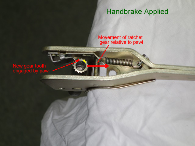
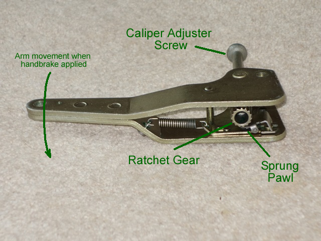
The handbrake system is self-adjusting using ratchet mechanisms to automatically compensate for the pad wear. The distance between the pad faces is determined by how far the caliper adjusting screw has been screwed into the ratchet gear.

When the handbrake is applied, the operating arm pivots on the pin attaching it to outer caliper arm. This effectively draws the caliper adjusting screw and attached inner caliper arm towards the outer caliper arm, resulting in a clamping force.

The pivoting action also allows the ratchet gear to move relative to the sprung pawl and the extent of movement is determined by the amount of pad wear.

As the wear increases, the movement becomes sufficient such that the pawl slides along the shallow slope of the ratchet gear tooth and its spring forces it to drop onto the next tooth.

The ratchet gear moves back relative to the pawl when the handbrake is released. However the pawl now engages with the steeper slope of the tooth resulting in a turning force on the ratchet gear.

This torque rotates the ratchet gear further onto the adjuster screw and therefore reduces the distance between the two pads. The photos above attempt to show the ratcheting process, although in reality the ratchet gear will only be tightened one tooth at a time.

All the moving parts a given a generous covering of Lucas green brake grease before the cover plates were added
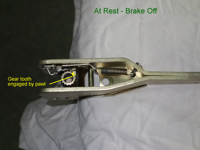
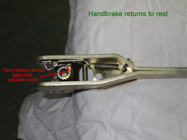
I’m not sure if there is a correct or recommended order for rebuilding the handbrake mechanism. I started with the internal parts of the operating arm; the pawl slots onto protrusions on the arm which guide and limit its travel. A tensioning spring attaches to the pawl and the other end to an anchor pin pushed through the operating arm.

The ratchet gear can then be installed which has a friction clip attached to its base. The clip provides sufficient resistance to stop the gear rotating when the pawl is gliding over the shallow tooth face. Once these were in place all the moving components were covered in high temperature brake grease.

The anchor pin for the return spring needs to be inserted into the outer caliper arm before the pads are fitted
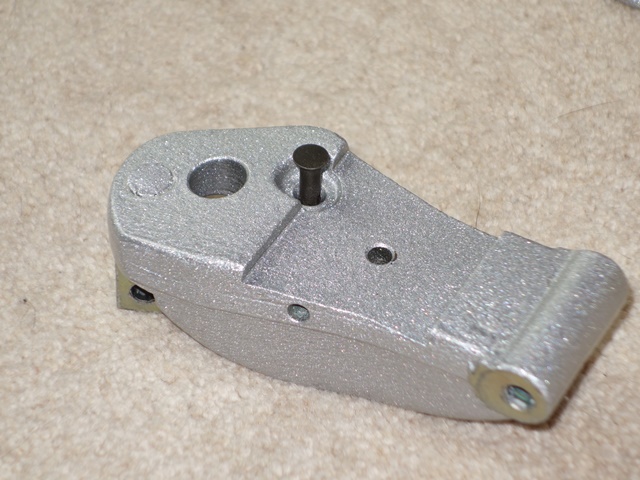
The operating arm could then be attached to the outer caliper arm. I found it easier to fit the operating arm return spring first which is attached at one end to an anchor pin pushed through the caliper arm and the other to a shaft in the operating arm.

Note: the spring passes through a protective cover so this needs to be positioned before the spring is hooked over the operating arm shaft.

The pivot pin between the caliper arm and operating lever was then inserted and fixed with a split pin. A slotted screw and nut then clamp the two protective covers to the operating arm.

Finally the inner caliper arm was attached to the caliper adjuster screw with another split pin and screwed into the ratchet gear to complete the rebuild.

The caliper adjuster screw is fixed to the inner handbrake caliper with a split pin

The completed handbrake mechanisms awaiting fitting

Brake caliper rebuild

 Brakes, Rolling Chassis  Comments Off on Brake caliper rebuild
Jun 242013
 

The components for the front calipers - including the small circular seals between the two halves
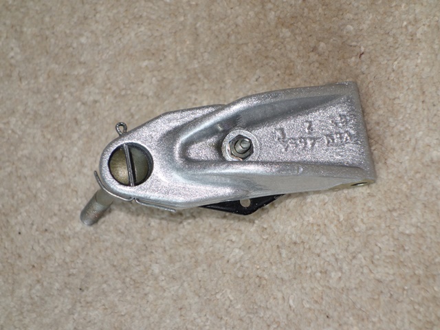
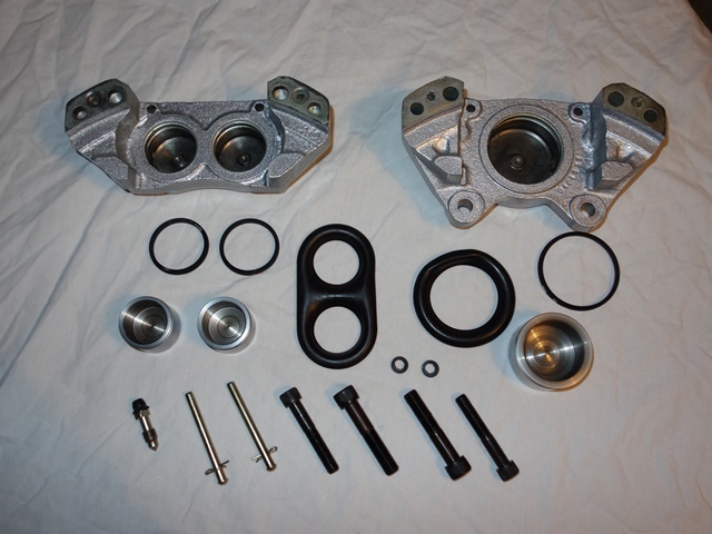
Caliper rebuild kits are readily available from many of the usual suppliers and contain the square sectioned seals which sit in recesses in the caliper piston bores and the outer dust shields.

The dust shields are similar to a expandable bellow with the ends sitting in a recesses in the piston bore and piston. This enables the rubber shield to stop ingress of foreign particles for the full travel of the pistons.

The kits however do not contain the small square sectioned ‘O’ rings that seal the two halves of the caliper.

I think the reason being that the manufacturer provides the following warning:

Girling “split” calipers should not be separated for any reason. They were not designed for separation and reassembly and proper torque specifications are not known, other than the inner and outer bolts are torqued differently.

It seems odd for the manufacturer to give the reason that the torque specifications are not known for their own product! I can understand their wish in avoiding customers trying to split the calipers in case they are not sealed correctly and the likely consequences. Again, being of a cynical nature, I suspect this has as much to do with fear of litigation.

However, when I contacted a caliper reconditioning firm, they suggested that as long as new seals are used and the bolts are sufficiently torqued there shouldn’t be a problem. Leaks were more likely to occur elsewhere. Although I will keep an eye on the calipers once in service … just in case.

Their recommendation was to torque the 7/16″ diameter bolts to 70 lb-ft and the 3/8″ diameter bolts to 40 lb-ft. Also to work from the outside in and alternating sides each time, ie torque the outer bolt on one side then the outer bolt on the other, followed by the inner bolt next to the first outer bolt and finally the remaining inner bolt.

The front calipers have internal passageways to enable fluid to pass between the two halves
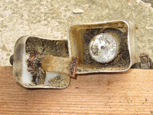
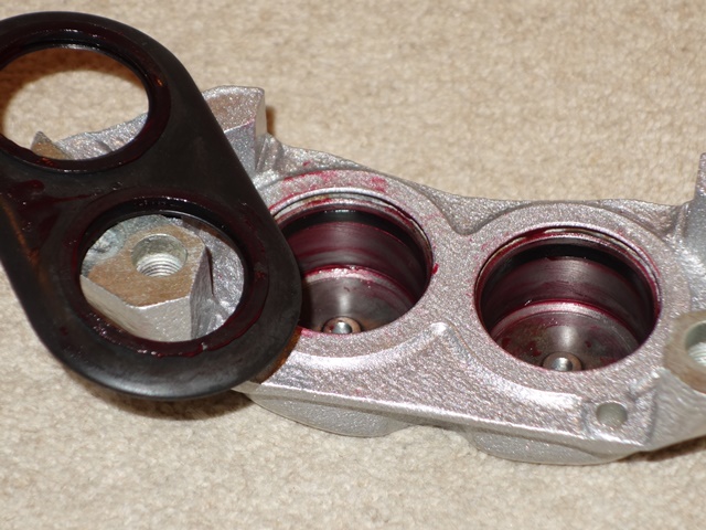
The photo to the left shows the passageways for the brake fluid from the face where the two caliper halves join (the tip of the screwdriver is just about visible at the top of the upper piston bore). A corresponding passageway exists from the face of the other caliper joint and a small channel links the two piston bores. Thus providing the free flow of fluid between all the pistons in both halves of the caliper.

The rebuild is very straight forward. The bores and seal recesses were given a coating of Castrol Red Rubber Brake grease before the bore seal and outer dust rubber shield were fitted.

Grease was also applied to the cylinders before pressing home. The main point is to ensure the pistons were pushed in squarely to avoid damaging the seals. The outer lip of the dust shield pops into place as the piston is inserted.

Piston bore greased and seal inserted Dusty shield inserted before fitting piston

The piston bore and seal recess were covered with Girling Red Rubber grease before the seal was inserted into the recess

The rubber dust shields are insered into their groove in the caliper before pressing in the piston

Two smaller pistons & combined dust shield Greased pistons before pressing home

The front is a 3-pot caliper so one half has two smaller pistons with a combined dust shield

The pistons are also given a generous covering of rubber grease to ease fitting

Finally the two small seals between the caliper halves were greased and inserted into their recesses and the caliper bolts tightened to the torque setting above.

A square section 'O' ring sits in a recess  and provides the necessary seal between the two halves of the front caliper

Completed front and rear main calipers

The main difference between the front and rear calipers is the rears employ an external pipe for the fluid to passed between the two halves and therefore there isn’t the need for the small seals.

May 192013
 

While researching the best piping to use for the hydraulics, I’d found out that copper piping is banned in many countries as it is susceptible to work hardening over time. I thought it wise to switch to Cunifer pipes as it is a safety issue, even though I had already purchased a copper pipe kit from Automec.

In the end I took the cautious approach to all the braking system and planned to have the master cylinder and servo units professionally renovated. The main reason being an inspection of the master cylinder had revealed some pitting and I wasn’t confident it would be possible to get a good seal without it being re-sleeved.

Also the fixing studs on the servo unit were all at odd angles so something was amiss. Opening up the servo uncovered a bodged weld ‘repair’ to one of the studs. The servo casing looked as if it had been fractured around the stud and so would need replacing. The units were sent off to J & L Spares to be repaired. However the cost of repairing the master cylinder was more than the cost of a new one so I opted for the latter.

Servo Mounting Studs Bodged repair weld Renovated Servo

The mounting studs for the brake servo were all at odd angles, suggesting all was not well

One of the studs appears to have been bent resulting in a fracture around the stud, whic had been poorly 'repaired'

A renovated servo unit from J & L Spares

Apart from a basic understanding, I’d never really paid much attention to the detailed workings of servo assisted brake systems. So it was out with the Jaguar service manuals to get a better understanding of how the vacuum boost is controlled. It should help if troubleshooting is required later on, especially as I will be tapping into the vacuum circuit for the EDIS Megajolt control module.

It’s actually quite simple. A reservoir tank stores a ‘vacuum’ by being connected to the inlet manifold, which is at a lower pressure than the ambient air pressure. This is then used to boost the braking force when the brake pedal is pressed.

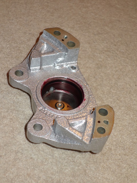
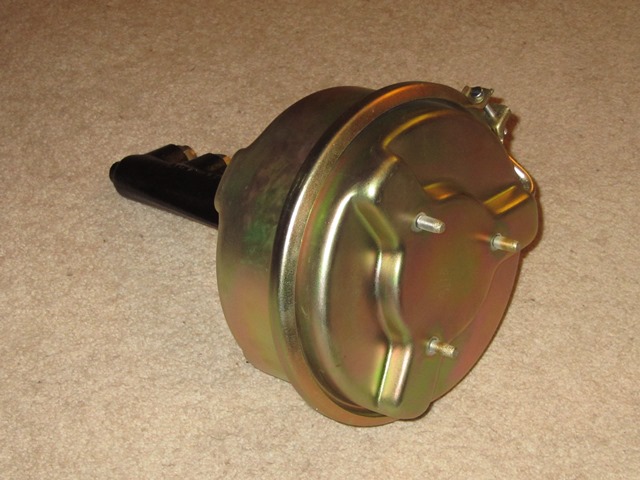
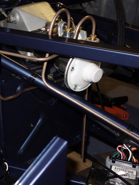
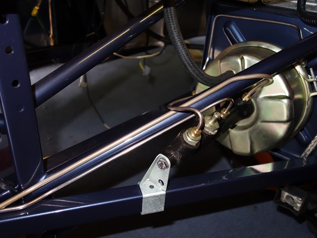
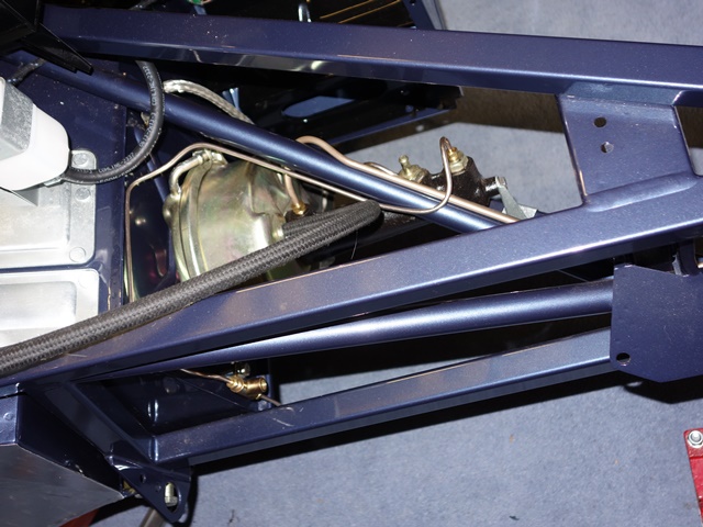
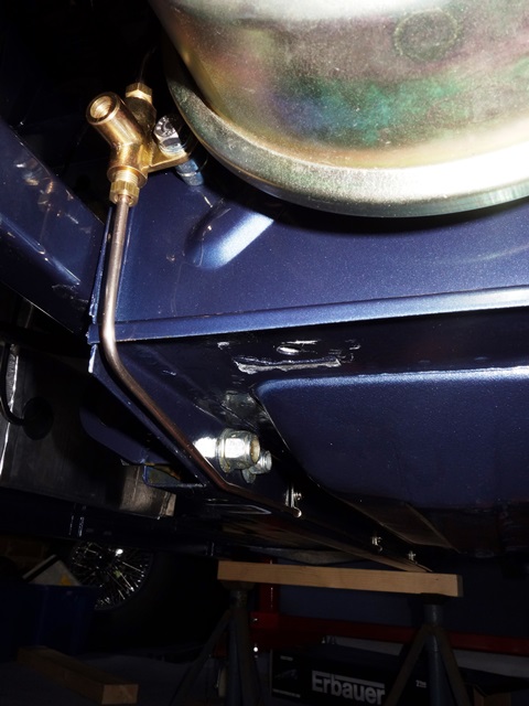
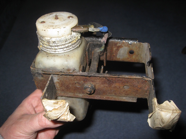
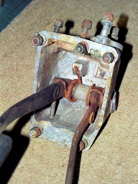
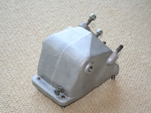
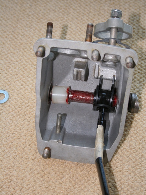
The servo unit contains to volume chambers which are both connected to the vacuum reservoir but separated by a diaphragm. The servo hydraulic piston is operated by fluid forced from the master cylinder but also by a spindle attached to the centre of the diaphragm.

At rest when no braking force is applied, there is no flow of hydraulic fluid and both chambers are at equal pressure and so no force is exerted on the piston.

However when the brake is applied, the master cylinder piston is pushed down the bore forcing fluid from the master cylinder to the servo unit. This operates the servo hydraulic plunger. Near the end of the travel of the master cylinder piston, it operates a reaction valve.

The reaction valve first disconnects the servo’s rear chamber from the vacuum supply and then opens the rear chamber to atmospheric pressure. This creates a pressure difference between the front and rear chambers, which forces the diaphragm and attached spindle forward. Thus increasing the force applied to the servo hydraulic piston.

Once these were installed on the car, it was time for the fabrication of the hydraulic piping ….

The brass fittings were salvaged from the Automec kit and the copper piping used for making mock-ups of the more complex sections. Cunifer piping is typically sold in 25 foot coils which was more than enough. So I had plenty spare ‘just in case’ I made a hash of making the individual pipes.

I now needed to straighten the replacement Cunifer piping and also to obtain a brake flaring tool. Initially I purchased a flarer from Machine Mart which was little short of useless and had the typical Made in China quality about it. I ought to know better by now!

There’s always a number of old, quality flaring tools on eBay but these usually change hands for well in excess of £100. I think people just resell them back on eBay once they’ve finished their restorations, which is what I planned to do. However after being outbid on numerous times I gave up as I needed to press on.

The Oakes brake flaring tool purchased from Automec was well worth the investment
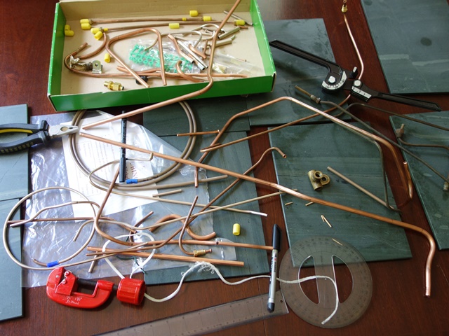
After a recommendation, I picked up a new Oakes tool from Automec at the Jaguar Spares Day for a show price of £90. Quite a bit for a tool for a one off job but it does produce good, consistent flares every time. All in all, a good investment and a quality tool.

I’d previously straightened all the copper piping over a form (covered in a previous post) but subsequently disposed of the wooden form, thinking I’d no longer need it!

I did come across a straightening tool produced by a company called Kwix UK which seemed promising. However it only straightens a pipe of a fixed diameter so I’d need three tools for each of the pipe diameters used for the brake and fuel lines.

One to avoid - the Kwix UK pipe straightener - it could be a good product but really let down by their customer service
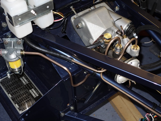
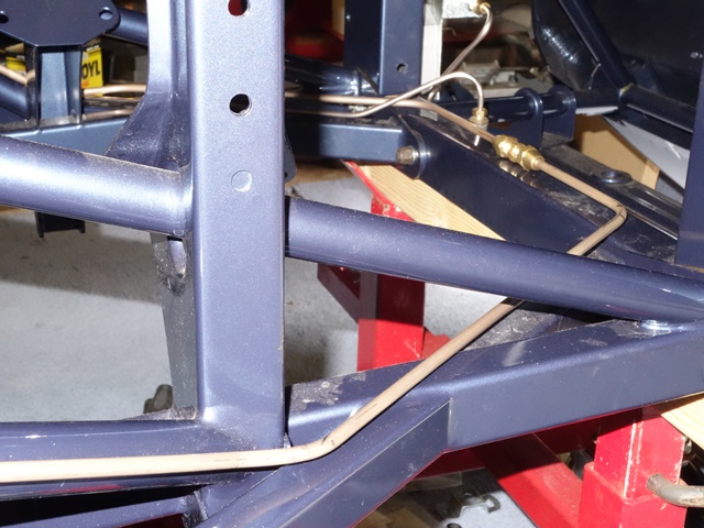
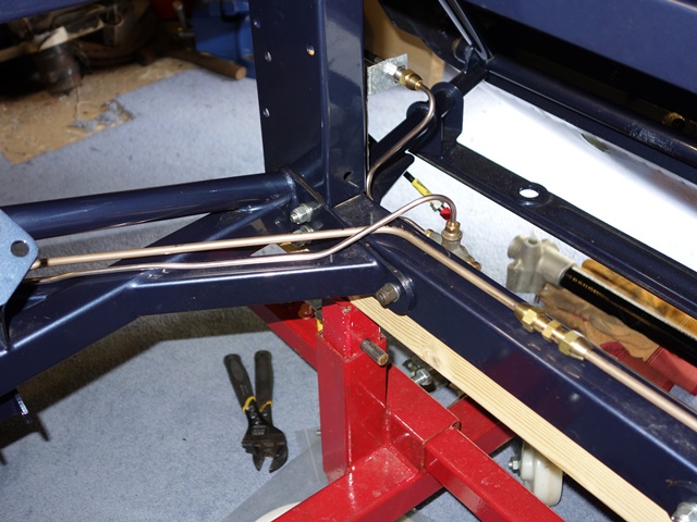
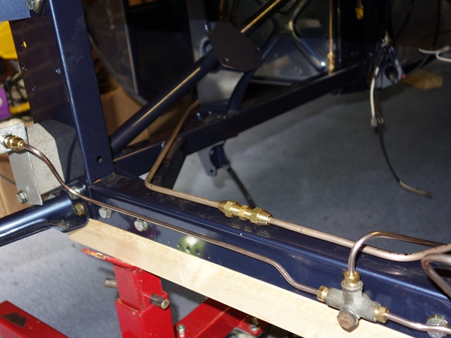
The 1/4″ brake pipes linking the master cylinder and servo run around the engine frames. I thought any slight bends/kinks in these pipes would be more noticeable as they run along the straight edges of the frames. The 1/4″ tool was purchased as a trial and it worked well so I got the 5/16″ one for the fuel lines.

Unfortunately this time, the pipe passed straight through without a hint of straightening and emails to the company received no response. I think they probably just sent the wrong sized tool but couldn’t be bothered with addressing customers’ issues so I won’t be dealing with them again!

The difficulty with bending the pipes was that often it wasn’t possible to trial fit the pipe after each bend was made. The unbent length would usually foul some part of the bodywork, stopping the pipe being placed in situ to mark the exact point for the next bend.

There was little margin for error for pipes that had to be bent in different planes. It only takes slight errors in the position of the bend, the angle of the bend or the plane in which the bend is made for it not to fit and the errors are magnified once another bend or two is added.

The clutch and rear brake piping, although the photos don't quite capture the various bends in numerous different planesThe mantra measure twice cut once applied here as, once bent, it’s almost impossible to re-straighten a pipe, especially the larger diameter piping. In fact it was more like measure 10 times, bend once! I probably had to discard just under half of my first attempts.

Having completed the hydraulics, I’m not convinced of the wisdom of purchasing kits as it would be nigh on impossible to get all the pipes right first time. So I’m glad I decided to fabricate my own pipes and it was quite therapeutic.

Having said that, I still managed a few numpty moments. A couple of times I allowed the brass fitting to slide away from the flared end onto the wrong side of where the bend was then made. Another scrapped length of piping!

The copper kit didn’t go completely to waste as it was cut down into shorter lengths and used to get correct position, angle and plane for a small section with say 2 or 3 bends. This could then be offered up without fouling the bodywork before making the same bends in the full length of pipe.

I had all but a few of the original pipes to use as templates however I did deviate in a couple of areas:

  • The pipe to the rear runs along the under floor box section but divert so it is clear of the mounting bolts for the torsion bar reaction plate. In doing so I think the pipe would be more exposed to damage. I continued running along the box section and will just need to take care when doing up the torsion plate bolts.
  • I thought it looked neater having straight piping around the front of the engine frames rather than trying to get them to mirror all the rises and falls in the frame profile. Therefore, just before the front brake union, the smaller front brake pipe jumps over the larger pipe rather than underneath.

Also my pipe bender couldn’t get as tight ‘U’ bends from the brake and clutch master cylinders and other methods were prone to causing the pipe to start collapsing.

Hydraulic Pipe Routing
Below are a few photos of the trial fitting of the various hydraulic pipes on the S2.

Clutch from Master Cylinder Clutch low pressure pipe

The routing of the clutch piping from the master cylinder to the flexible hose union. Note - not fitted at this stage is the P-clip on the LH frame bolt, securing the pipe

The clutch low pressure hose has a tight U-bend before running parallel with the engine frame

Brake – Master to Servo Brake – around Picture Frame Brake – Master to Servo & To Front

The brake pipe from the master cylinder to the servo unit also has an initial tight U-bend before running down the diagonal, round engine frame

The pipe then routes around the bottom of the picture frame to an inline union

From the union, the pipe travels up the opposite side frame member to the servo unit.

Front feed over Master to Servo Left Front Brake Righr Front Brake

The feed fro mthe servo to the front brakes first passes underneath the thicker master to servo pipe and then over it to the front union

The left brake pipe from the front union

The right brake pipe from the front union

Servo to Rear Union Union to Rear A few off cuts!!

The path of the pipe for the rear brakes from the servo to an inline union, which includes the brake light hydraulic switch

From the brake light switch union, the rear pipe passed down the LHS of the underside of the car

The fitting of the clutch and brake pipes was definitely a case of practice makes perfect - a few off cuts!

Jan 232013
 

The brake reservoir caps house electrical connections for the float operated switch for the brake fluid warning light and appeared to be quite corroded. It was only once they had been opened that it became clear that what I thought was corrosion was probably crystallised hydraulic fluid.

Both the reservoir caps appeared to be corroded but it was actually crystalised hydraulic fluid This was most of the contents of the first reservoir! The second reservoir was not much better!

The float should be enclosed in an aluminium cylinder but most of this had corroded away. I had little option but to replace the reservoirs which was a shame. Replacements are readily available however an alarming number of people had reported problems with them splitting and the resulting leak causing havoc with the paint work.

Reading other people’s woes with the repro products, I think the splitting might be initiated either when the black low pressure rubber tubing is pushed on, as a reasonable amount of force is required, or by over-tightening the hose clamps. Basically the new parts are not particularly good quality and no doubt originate from China.

The original bottles had a metal insert inside the supply protrusion/outlet which would avoid the over-tightening issue. The insert also had a gauze nylon filter, again missing from the new ones.

The clutch reservoir was better as the fluid hadn’t crystalised, which I’m now thinking might be caused as the aluminium float shroud corrodes. However there was a lot of gunk at the bottom so I thought it wise to replace as well.

Reservoir cut open to retrieve the metal insert

I decided to salvage the metal inserts by cutting the bottles in half. These were zinc-nickel plated along with the bracket clamps before being inserted into the new bottles. The method I use to insert them was to pass a piece of string through the supply outlet to act as a guide.

A rod was then used to carefully push the insert home while supporting the other side to minimise the stress on the plastic bottle. The reverse was done when pushing on the low pressure rubber tubing, opposing the pressure with the same rod. Hopefully it will be ok.

I couldn’t work out a method of refitting the nylon gauze filter on to the metal insert once it was in place. The filters were not in the best of shape so they have been omitted.

Brake and Clutch reservoirs reunited with re-plated bracket Brake Servo reservoir showing the aluminium shroud around the float

However this does lead on to my next dilemma. As the calipers have been reconditioned and the reservoirs and hydraulic pipes replaced, I have the opportunity to switch from DOT4 to silicone brake fluid.

I like the idea of using the silicone fluid to avoid potential future problems with leaks damaging the paint work, especially in light of the problems others have had with the new reservoir bottles. Conversely there are views that the rubber seals can be damaged over the long term by the silicone.

It seems there isn’t a general consensus on which is the best way to go and it’s difficult determining whether advice is based on fact or merely that the person went down that route themselves and therefore it must be the right choice! Hmmmmm ……

Apr 242012
 

I was surprised how rusty the clutch pedal and pedal springs were seeing it’s inside the car and underneath the aluminium pedalbox housing. I’m assuming this must have been as a result of condensation. Once it’s complete I’ll give the inside a covering of ACF50 to give it some protection. There’s nothing worth noting on the dismantling as the pedals simply rotate on a shaft through the pedalbox.

The pedalbox was renovated before I’d come across the company that ultrasonically cleans alloy components, so it was shotblasted and then coated with a lacquer product sold by Eastwood to stop surface oxidisation. The pedal arm, foot pads and springs were also shot blasted and then powder coated.

The rebuild was fiddly mainly because the pedal springs are quite strong so it’s difficult to align everything while pushing the shaft into position. The final washer had a tendency to drop out at the final moment! It made sense to cover the shaft and mating surfaces in plenty of grease.

I was surprised that the brake light switch is actually part of the hydraulic system, actuated by hydraulic pressure when the brake pedal is pressed. Some have reported problems with the response of this switch and have therefore either replaced it or supplemented it with a mechanical microswitch operated by the brake pedal.

While the car is apart and the looms are being put in place, it makes sense to install both a hydraulic switch and a microswitch in parallel, to build in redundancy. All it would require would be to fabricate a bracket to hold a microswitch in the pedalbox housing. I’ll do this as part of the final electric fitting when the lights are installed.