
There’s been a dramatic drop off in progress with the restoration in the last month or so. Partly due to the horrible winter weather, resulting in an apathy to venture out into a cold, dark garage!
In the meantime, attention has turned to sorting out bits and pieces that could be worked on indoors, although it gives an excuse for the gratuitous inclusion of some photos of the main reason for the lack of headway … a diving trip in warmer climes!
| Progress is delayed due to a spot of diving …. with some immature 6m Whale Sharks | ||
|---|---|---|
 |
 |
 |
Back to the plot …..
Several years ago I’d come across an owner’s restoration of a ’63 OTS where they had redesigned the looms to their own specification, incorporating relays for the headlight circuits. The addition of relays made good sense, as they remove the main current bearing wires from behind the dash area, but I wasn’t convinced about having bespoke wiring looms made.
Deviating too far from the original wiring looms would mean that, if I subsequently encountered electrical problems, I’d be on my own as it would be hard seeking accurate advice from fellow owners. There was also the fear of overlooking a critical wire when the looms were made up or getting the length of one of the wires slightly wrong. It would be an expensive mistake to fix!
So the idea of adding relays was shelved and a new set of standard looms purchased. Fortunately this proved to be the right course of action. At the time, I hadn’t spotted the wiring diagrams I was using weren’t correct for my car. They didn’t have the changes in circuitry covering the introduction of the ballast resistor into the ignition circuit.
Rather timely, as I was starting to look at the lighting and bonnet electrics, an excellent write up of a headlamp relay modification was covered on the E-Type forum. The installation is very discreet with the relays being mounted out of sight behind the LHS ‘sugar scoop’. The only visible sign of the modification is the main power feed, taken from the alternator B+ terminal.
The downside of tucking the modifications within the bonnet is that it will be much trickier to maintain if something fails. The headlight bowls and possibly the indicators would need to be removed to gain access.
 I had some spare repro 6RA relays so all I needed to purchase were some suitable coloured & rated wires and two in-line fuses. I also decided to install Halogen headlights at the same time.
The circuit diagram shows the planned wiring modifications, with the additional components labelled in red.
There are two spare terminals in the 8-pin bonnet plug, which were originally for the bonnet mounted horns found in the earlier cars and, I believe, the provision for optional extra spot/driving lights.
 One of these spare terminals was used for the single high load wire running from the alternator B+ terminal to the 10-way connector in the bonnet. (It’s much easier to take a supply from the B+ post rather than travelling all the way back to the battery.)
I managed to feed the wire into the PVC sleeving to the bonnet plug so the only visible sign of the installation in the engine bay is a single sheathed wire running from the alternator to the bottom left of the picture frame, which has been cable tied to the existing loom.
From the bonnet connector, this feed splits in two to provide the 12v supplies to the dipped and the main beam relays. The relays have a double spaded terminal for the switched output, so the wires to the left and right hand lamps were connected directly to the relay.
Wire and fuse ratings
The Halogen dual filament bulbs are rated as 55W/65W at 12v so the dipped and main beams for each bulb will draw around 5.5 amps and 6.5 amps respectively (assuming a charging battery voltage of 14.3V).
Normally only one set of the filaments are on at any one time. However the worst case is when the main beam is ‘flashed’ while the dipped beams are on. Even though this should only be for short periods of time, I thought it prudent to assume the maximum current required for both headlamps would be 24 amps (2 dipped @ 5.5A each and 2 main beam @ 6.5A each).
Therefore 44/0.30 cable, rated at 25 amps, has been used for the supply from the alternator rather than the 28/0.30 cable suggested in the forum write up. Inline fuses have been used for the connections to the two relays. Their wiring is rated at 30 amps which is more than enough, although they have both been fitted with 15 amp fuses as the expected loads are 11 amps dipped and 13 amps main beam.
 Using two fuses should ensure that a blown fuse won’t result in the complete loss of lighting!
The original wiring for the dipped beam (Blue/Red) and main beam (Blue/White) will now just be used to switch the relays. The coil resistance for the 6RA relays was measured at approximately 83 ohms so the switching wires will now only need to carry around 0.17 amps. Therefore the dash mounted fuses 1 & 2 have also been replaced, by 0.25 amp fuses.
As the whole bonnet area had been coated in copious amounts of Waxoyl, I also fitted some PVC sheathing to the bonnet loom in an attempt to keep it clean. I just need to tidy up the cabling when the headlamps are fitted.
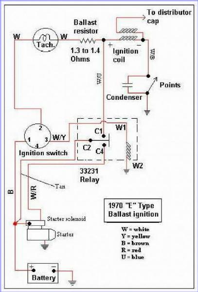 Around the end of ’69, a ballast resistor was introduced into the ignition circuit with the aim of improving cold starting. The original 3 ohm coil was replaced by a ballast resistor and coil wired in series, both being around 1.5 ohms. When the ignition switch is turned to start the engine, the starter relay activates, delivering power to the starter solenoid but also bypassing the ballast resistor.
 It was a good opportunity to get Autosparks to make up the additional wiring, using the correct colour coding, that I needed for the few upgrades I’d planned – the mechanical brake light switch to supplement the hydraulic switch and the boot light.
 It was only once I came to fit the voltage regulator bracket that I found out that its mounting holes had been punched in the wrong place. They were about 5-6mm too close to the sill closing panel so that the bracket doesn’t fit. The bracket did change for the S2 cars so it might be that the panel also changed and I was supplied the wrong part.
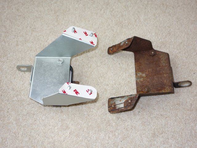 The problem I find with zinc plating is it’s too blingy (although I’m sure the brightness would dull slightly once exposed to the elements). I decided to experiment and sprayed it with a two-pack clear satin lacquer. The results were even better than I had hoped/expected. The satin finish obviously tones down the brightness but it also has a softer, smoother to the touch feel and a more uniform metallic finish.
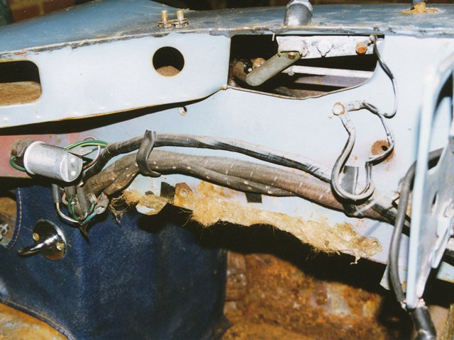

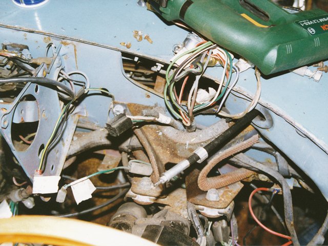
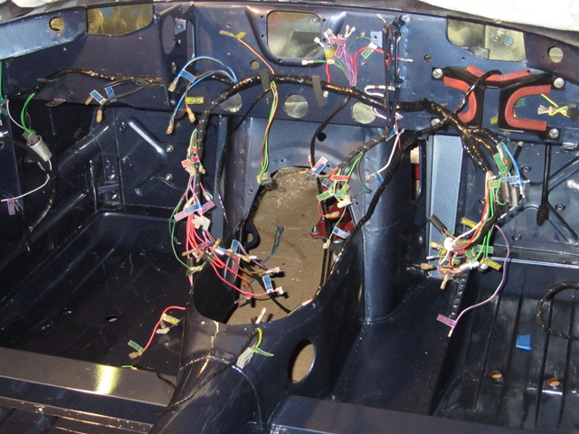


 Somehow the old loom had turned itself into a right old bird’s nest while in storage. It took quite a while to untangle it so that it could be laid out, mimicking how it is routed within the car. Armed with a multi-meter and the wiring diagrams, I set about the simple task of labelling the new looms …
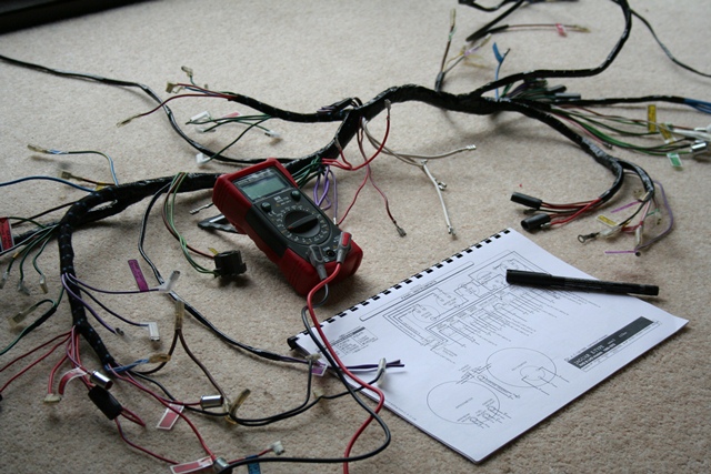 Other issues that, for now, remain unresolved are i) a missing green & brown wire for the reverse light switch and ii) a spare purple & white wire at the centre of the dash. The E-Type forum is very helpful in cases like this as there’s a wealth of knowledge available from the forum members. I was not alone with both the missing and extra wires as one member had decided to use the spare purple & white wire for the reverse light switch. Perhaps I’ll need to do the same.