
My aim is to spend a long weekend in August (with the wishful thinking that it’ll be sunny!) to transform it from a bodyshell into a rolling chassis; installing the fuel system, rear suspension, engine/gearbox & ancillaries, front suspension and steering all in one hit. So I’ve got my work cut out to get everything ready in time.
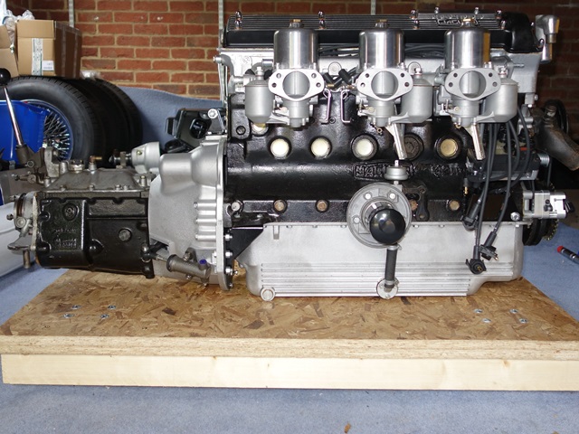
The bonnet and front sub-frame need to be removed in order to fit the tiny radiator support brackets so I’m also going to remove the picture frame at the same time. It should then be possible to roll the engine and gearbox unit into place through the gap and avoid the hassles of installing the engine either from above or below.
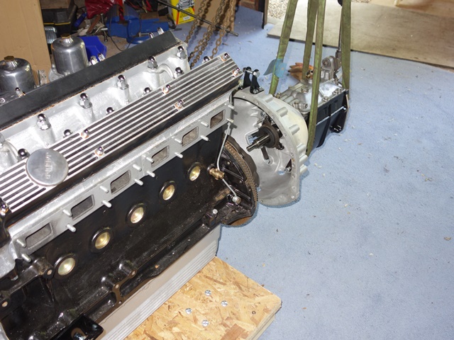
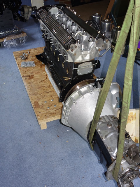
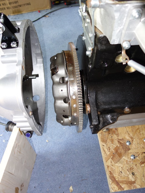
The gap between the lobes at the lower front edge of the engine frames is only 22cm. However, if the water pump is removed, the engine is slightly narrower than this just below the height of the inlet manifold. The engine has been rebuilt by VSE with a new clutch fitted so I just had to attach the gearbox and bellhousing. However the reuniting of the transmission unit would feel like a major milestone had been reached!
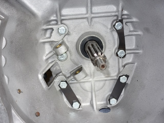 The bellhousing had already been ultrasonically cleaned and just needed the rear oil seal inserted before being bolted to the gearbox. Three lock tabs are used to prevent six of the bolts from working loose. The remaining two bolts, next to the clutch fork, use safety wire instead.
I’d never needed to use locking wire on previous vehicles so needed to purchase a pair of safety wire pliers. Eventually I managed to obtain an old pair on eBay and some 0.81mm stainless wire.
The pliers were definitely a good investment, less so was the wire that I purchased. It snapped as soon as a few twists were applied. I hadn’t purchased annealed wire – dooh! After purchasing the correct type, it was a lot more successful! The main point is to make sure the wire passing round the outside of the bolt head puts tension on the bolt in a clockwise direction.
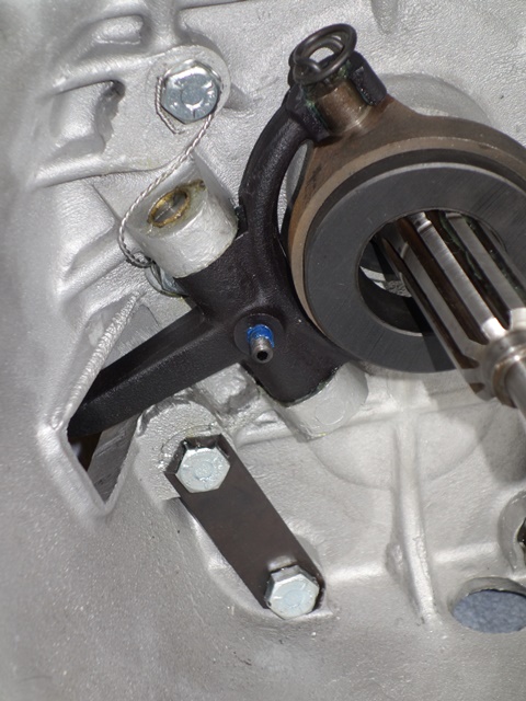
The fitting of the clutch release bearing and operating fork is all very straight forward. The fork can be inserted with the bearing attached which makes fitting the securing spring clips much easier. The clips are held in place by the curved end sitting in a slight dimple in the fork arm.
|
|
|
|


The engine was already sitting on the DIY trolley which will be used to roll it into position once the front frames are removed. Hoisting the gearbox to the same level meant it was simply a matter of rotating it to align the drive splines. Once the splines were engaged the gearbox could be rotated back again to align the bolt holes.
|
|
|
|
The two bellhousing support brackets needed to be installed before the full weight of the gearbox could be released. Finally the flywheel cover plate was bolted on to finish the job.
I did make the mistake of fitting the clutch slave cylinder when fitting the bellhousing to the gearbox but had to remove it to fit the lower bolt for the support bracket. I’ll make the final adjustments of the clutch just before the engine is installed.
One thing I’m not sure about at this stage is the orientation of the four vertical bolts for the support brackets. One of the bolts is longer than the others and so I guess must be used to secure a bracket of some description. Another question for the E-type forum ….
|
|
|
|

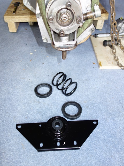
The gearbox is supported at the rear by a large spring between a mounting bracket and the gearbox. The spring damps the movement of the gearbox but allows for a degree of vertical travel. The spring ends sit in rubber mouldings. The mounting bracket also contains a rubber bump stop to limit the gearbox travel.
Sorry, the comment form is closed at this time.