
My initial plans were to upgrade the brakes to vented discs with calipers from either Zeus or Coopercraft. By all accounts deficiencies with the original S1 brakes were addressed for the S2 cars so I’ve had a change of heart and will be fitting the original braking system for now. I’ll see how it goes and decide on any changes once I’ve driven it for a while.
All the calipers were sporting many years worth of brake dust, dirt and grease and were to be stripped back, cleaned and rebuilt. The rears were worse but once liberated from the IRS unit they were fairly easy to dismantle.
|
|
|
|
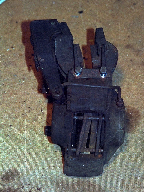

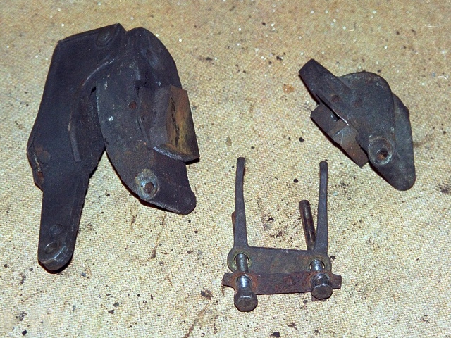
The handbrake mechanism was simply removed from top of the rear calipers by knocking back the lock tabs and removing the two retaining bolts. The other differences between the front and rear calipers is that the fronts have three pistons compared with two at the rear and the rears have and external hydraulic pipe connecting the two halves.
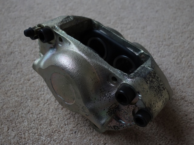
At the start I was somewhat bemused how one half of the front caliper worked as it didn’t appear to have any hydraulic feed. Obviously there must be an internal passage to transfer the brake fluid but I couldn’t see how the clamping force alone would create the necessary seal between the two halves of the caliper.
All became clear once it was split in half. In the middle of both clamping faces was a channel to the rear of the piston chamber thus providing a path for the brake fluid to flow between the two halves. Machined recesses contained rubber washers which would be compressed to create the required seal.
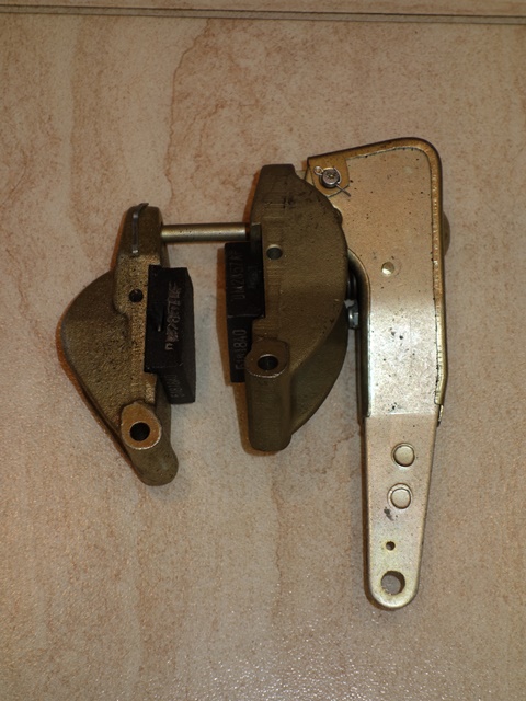
Unfortunately I’d not documented the rebuild of the calipers as it was done a number of years ago and they had been stored ever since. To my dismay, when I dug them out again, the zinc plating had already started to corrode …. and that was after storing them indoors!
|
|
|

It was probably due to poor plating but they’d certainly look quite shabby very quickly if they were fitted to the car and exposed to the elements.
The calipers would have been cadmium plated which isn’t an option nowadays due to the toxic chemicals involved. I’m relaxed over deviating from originality, especially for practicality reasons, and decided to strip them down again and paint them rather than re-plating. So it was another case of one step forward and two back!
The problem with the plating was limited to the cast iron components so only the main calipers and handbrake caliper arms will be painted. The handbrake ratchet mechanism will be left as passivated zinc.
 The easiest method of extracting the pistons was to insert a bleed nipple into the hydraulic feed and use a foot pump to force the pistons out.
It’s a good idea to place a piece of wood between the pistons to limit their travel. The pistons can be pushed out in stages be reducing the thickness of wood each time. This enables all of the pistons to be pushed out rather than one popping out and the rest staying put.
It was also necessary to separate the handbrake caliper arm from the ratchet mechanism by removing the split pin and pressing out retaining pivot pin. The internal spring could then be removed more easily.
|
|
|

The calipers were first soaked in a hot degreaser and then the joint faces and piston bores masked ready for painting. The paint kit ordered from Brake Caliper Specialists was a 300ml two pack paint (200ml paint & 100ml hardener) specifically designed for calipers, which was sufficient for all four main calipers and the handbrake caliper arms. Hopefully the 2 pack paint should prove more durable than other VHT paints.
|
|
|


All that remains is the caliper rebuilding ….
 In my hour of need I turned to E-Type International Rescue – McLaren’s Skunk Work team. There was some bemusement as to why the kit contained a pack of 9 shims rather than machining the wishbones correctly.
  The ball joint bores were profile milled with a ball-ended tool around the circumference, progressively stepping down after each revolution until it had cut to the required parallel depth.
 I briefly tried applying heat but all this did was burn the rubber bushes, producing acrid smoke. They eventually came free after applying penetrating oil over a period of several weeks and then jumping up and down on the end of a very long lever, inserted between the floor pan and the radius arm. To the untrained eye, the jumping up and down in a frustrated, childish manner while shouting ‘aaaargh!’ might have come across as a method of last resort …. but it worked!

