
There was slight play in the upper steering which was found to be caused by a broken wave washer in the lower bearing components. Otherwise it appeared to be a simple matter of giving the painted parts a fresh coat of paint before rebuilding.
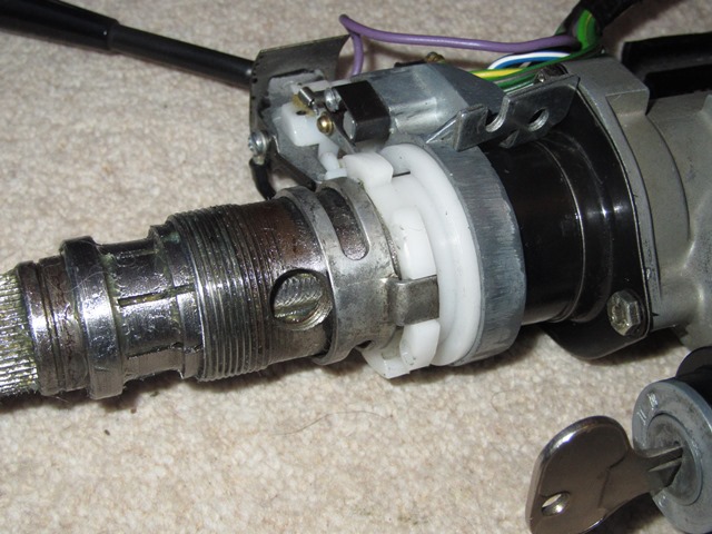
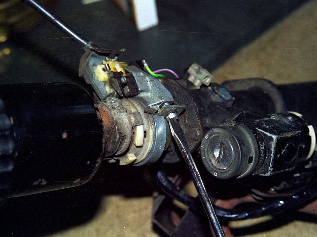
The ignition switch introduced for the S2 cars incorporated a steering column lock and is secured to the steering column housing with a security bolt. The hexagonal part of the bolt is designed to shear at a certain torque. Therefore, once in place, the only way of removing the switch/lock would be to drill out the remaining rounded head.
| Steering column components | Steering lock security bolt | Ignition switch secured |
|---|---|---|
 |
 |
 |
First the outer column shaft needs to be secured into the column housing. The shaft is fed through the upper roller bearing into the housing and then locked into position by the lower bearing. The lower bearing and seat fit under a larger retaining cap and then a series of washers is fitted before the final circlip.
| Outer column shaft | Upper roller bearing | Lower roller bearing |
|---|---|---|
 |
 |
 |
One of the washers under the circlip is a wave washer which provides a spring pressure once compressed. This preload removes the free play of the column shaft within the column housing.
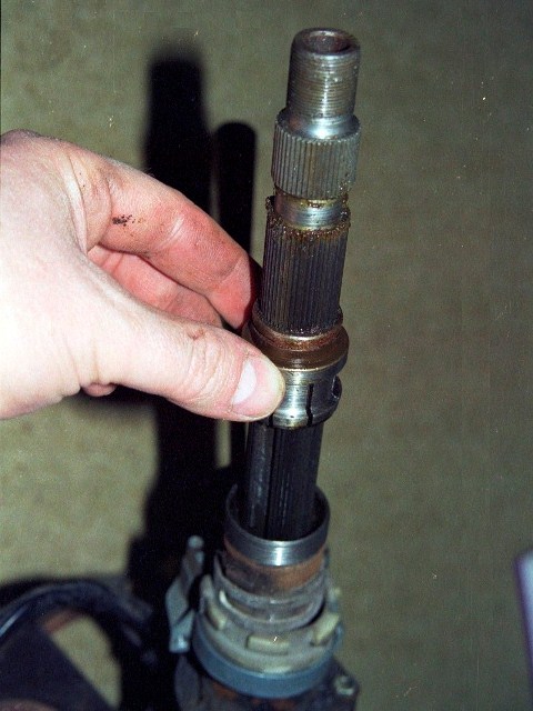
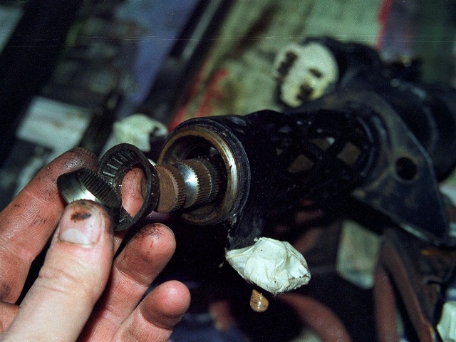
The inner and outer shafts engage on splines so the torque applied at the steering wheel is transferred from the inner shaft to outer shaft and finally on to the steering rack. However the inner shaft can slide longitudinally into the outer shaft to provide a level of adjustability in the steering wheel position. The rightmost picture below shows the inner and outer column shafts at both ends of their adjustability.
| Fitting splined bearing race | Retaining cap over bearing race | Adjustability of column shafts |
|---|---|---|
 |
 |
 |
The stop button screwed into the outer shaft protrudes into a slot machined into the inner shaft, thus limiting its length of travel. A locking nut in the shape of a large black cup (not shown) is attached to the split collet by a circlip. When the cup is rotated clockwise it screws further onto the thread at the end of the outer shaft, compressing the collet and locking the inner and outer shaft together. Similarly rotating it anti-clockwise allows the collet to expand sufficiently, to unlock the shafts and enable the steering wheel to be adjusted.
The photo also shows the two nylon pins that enable the steering column to collapse. If the steering wheel is hit with sufficient force, such as in the event of an accident, the pins shear allowing the lower section of the outer shaft to slide into the upper section. At the same time the lattice structure of the column housing will also compress.
 Finally to the trickiest part of the rebuild – the fitting of the indicator stalk mechanism. One which caused quite a bit of head scratching! Although in my defence, this was because one of the critical parts was missing. A previous owner had obviously taken the indicator off at some stage and bodged the refitting.
The missing item was the retaining clip (19). The correct fitting is the two screws pass through both the clip and a packing piece (16) and into the threaded holes in the indicator body. The combination of these two parts ensures that the rotational parts of the indicator are concentric with the column shaft.
The previous owner, Cap’n Bodger, had used the packing piece as the retaining clip as they are fairly similar in shape. However without a packing piece in the correct position, the indicator housing had been pulled too close to the steering shaft.
Over time this had worn down the white nylon ring operating the indicator mechanism. Unfortunately you can’t buy the nylon ring on its own and so the only solution was to purchase an entire replacement indicator stalk unit. However this still wouldn’t resolve the problem of the missing clip, which is no longer available from all the usual suppliers.
 Even Google and eBay searches hadn’t found anything so the only option would be to fabricate one based on the packing piece. The completion of the steering column was put on hold for a month or so while I pondered what to do. When it was picked up again, I made one final eBay search, just in case …. a USA auction for a clip had finished two weeks ago although without any bidders.
A speculative message was sent on the off chance they still had the clip. Shortly after came the reply that they did and a deal was done within an hour of contacting them. Result!
Back to the rebuild. The indicator stalk unit (13) followed by the indicator drive clip (9) are passed over the inner column shaft. The indicator packing piece (16) can then be placed in position but the corresponding clip (19) isn’t fitted at this stage as it will be necessary to move the indicator stalk unit and drive clip around to fit other parts. However once these parts are fitted it would be very difficult (if not impossible) to insert the packing piece. I fitted the split collet at this stage although this can wait until the cup-shaped lock washer needs to be fitted.
The packing piece has a small round protrusion which is aligned to fit into the corresponding hole in the indicator unit mounting bracket. This ensures the indicator stalk is at the correct angle once everything is mounted to the bulkhead. (Note: my mounting bracket had two holes and therefore possible indicator angles, I’ll adjust later to the preferred position)
| Protrusion on packing piece | Hole in mounting bracket | Exposing stop button hole |
|---|---|---|
 |
 |
 |
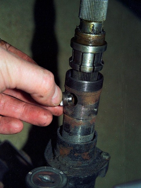
The indicator stalk unit and the drive clip need to be pushed towards the steering column housing to fully expose the hole for the Stop Button so it can be inserted. The raised section of the stop button should end up near to being perpendicular to the column shaft.
The drive clip must then be push away from the steering column until it rests against the raised section of the stop button. This will expose the screw holes for the clamping bolts which secure the drive clip. Once clamped, this will obviously also lock the stop button in position.
| Drive clip locks stop button | Drive clip bolts & washers | Finally the clip is fitted |
|---|---|---|
 |
 |
 |
The clip to lock the indicator stalk unit and packing piece tightly into position can now be attached.
 The tab on the drive clip needs to engage with one of the slots in the white nylon indicator ring. Therefore when the column shaft is turned the nylon indicator ring turns at the same time.
A tooth on the rotating nylon ring will then engage with the cancelling arms to automatically cancel the indicator when the wheel is turned.
When connecting up the whole steering column on its various splines, the wheels will need to be in the dead ahead position and the indicator cancelling tooth mid-way between the cancelling arms.
 The final components to go on are the split collet (although I had added this much earlier) followed by the large black cup shaped locking nut, which needs to be fully screwed onto the outer column shaft to reveal the circlip groove inside.
Fitting the circlip locks the two together and completes the upper steering column rebuild.
Later the steering wheel & boss will to be attached to the inner shaft. Once the split cone has been located in its grove, the splined steering wheel boss slides onto the inner column shaft until it meets the split cone and the central nut locks everything in place.
Steering Rack Fail Safe
Although the steering rack had been fitted for a while, I hadn’t added the steering rack fail safe bolts. Now the upper steering column had been completed it was time for a complete check of the steering system and fathom out the fail safe set up.
Note: this is only my understanding/interpretation of the fail safe as I see it, based on common sense rather than any qualified knowledge.
Rubber steering rack mounts are used to absorb some of the impact that would otherwise be transmitted directly through to the steering wheel if solid mounts were used. Therefore the ability to steer is totally reliant on in the integrity of the rubber and its bonding to the metal mounting plates.
The purpose of the fail safe set-up is therefore twofold; to maintain a level of steering input if the rubber/bond failed but, in doing so, avoid introducing any harshness to the steering feel that the rubber mounts were designed to remove.
Essentially the fail safe needs to allow the rack to move unhindered on its rubber mounts but to ‘catch’ it and limit its travels if the rubber fails.
Large retaining washers are fitted under the heads of the fail safe bolts. The bolts then pass through holes in the steering rack before being secured to the picture frame.
However retaining washers do not exert a clamping force on the rack and the holes in the steering rack are almost twice the diameter of the bolts. Therefore the rack is free to move on the rubber mounts.
Jaguar used different components for the driver and passenger sides but both are designed to achieve the same result; to stop the fail safe bolt & washer exerting a force on the rack.
| Passenger Side Fail Safe – with lock nuts | Driver Side Fail Safe – with spacer tubes |
|---|---|
 |
 |
On the driver side, spacer tubes are fitted over the bolts. The length of the spacer ensures retaining washers are just proud of the steering rack. The spacer diameter is marginally smaller than the holes in the rack so rack movement is still not restricted.
On the passenger side, lock nuts are fitted to the bolts (or more correctly setscrews) instead of the spacer tubes. The lock nut and Nyloc nut secure the bolts to the picture frame so that the washers under the bolt heads are just in contact with the rack. Again, as it is only lightly in contact, it does not restrict the free movement of the rack.
If either rubber fails, the rack will only be able to move a small distance until the fail safe bolts or spacer tubes come into contact with the edge of the holes in the steering rack.
The question of why Jaguar used different components on each side of the car has been asked many times on the E-Type forum but there’s never been a definitive answer.
My guess, and it is a guess, is that the use of spacer tubes is a compromise between allowing the rack to move freely on the rubber mount and the need to provide sufficient steering input in the event of a failure by limiting its free travel.
The manual specifically states the spacers are to be fitted on the driver side of the car, so regardless of whether the car is LH or RH drive, the spacers will always be at the pinion end of the steering rack.
I suspect, if the rubber has failed, limiting the range of free travel is more critical at the pinion end where the steering column attaches. The spacers would reduce this range considerably. The trade off, in normal use, would be that the spacers are more likely to impact the edges of the steering rack holes on heavier impacts and therefore transmit more unwanted harshness to the steering wheel.
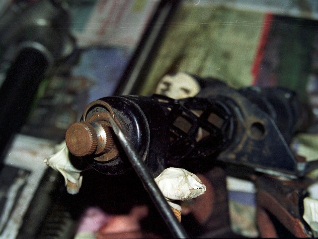
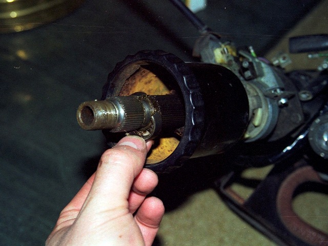 I was surprising how much force was needed to loosen the nut. It was necessary put on full lock and then use an extension tube over the socket wrench handle to get enough leverage.
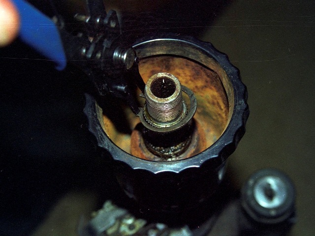
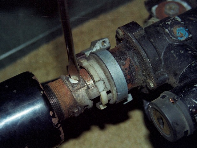

 At which point the key needs to be turned in the ignition to withdraw the steering lock. This enables the female inner column to be removed.