
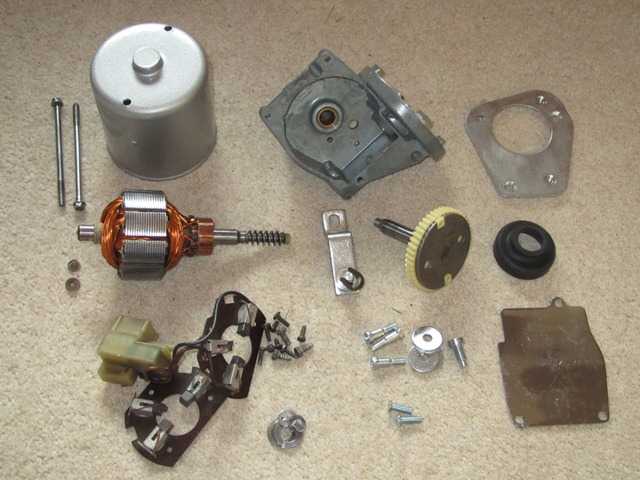
As with all the other electrical units, the alloy parts were was ultrasonically cleaned and then sprayed with Gtechniq S1 SmartMetal while the other steel parts were zinc-nickel plated. The next two tasks were to sort out the gearbox lid which had been distorted and also to strip and paint the yoke.
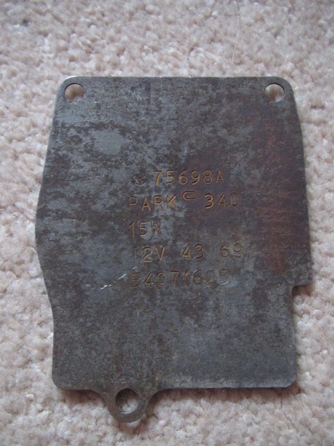 The centre area of the gearbox lid has been stretched at some point. Therefore its outer perimeter no longer made a continuous seal and so would allow water into the gearbox housing.
The suggested solution was to heat shrink the centre section of the lid to reverse the deformation – heating the centre of the lid to near red heat and then rapidly cooling. After several attempts of heating the lid with a gas blow torch and cooling using a can of compressed CO2, all I succeeded in doing was to work harden it in exactly the same shape as before. Aaaaaaargh!
It probably needs to be heated to a much higher temperature using oxy acetylene. In the end I cheated to avoid holding up the rebuild and obtained a replacement lid. When I get time I’ll give it a proper go at flattening the lid, as I would like to keep the original with the correct stampings.
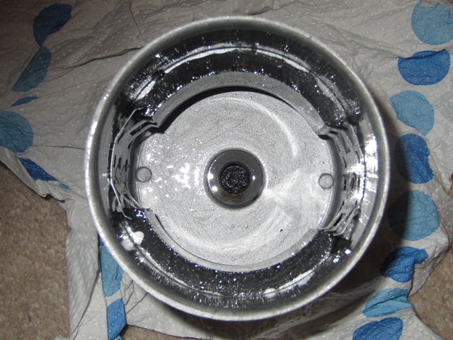
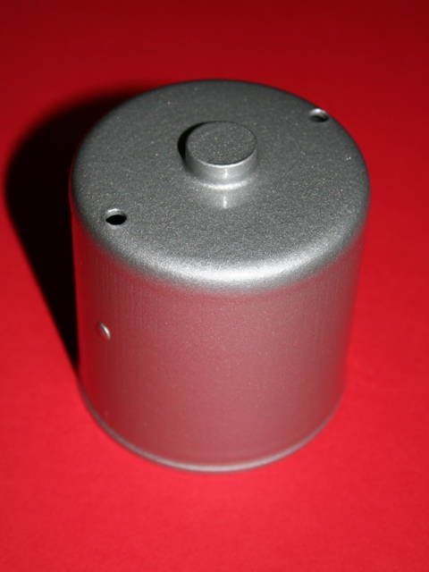 Next up was the yoke which contains the two permanent magnets. The magnets can be removed by lifting the retaining clips so the yoke could then be shot blasted before being painted in silver hammerite. I was quite pleased with the finished article even though the silver hammerite was not quite the correct colour.
During the refurbishing of the cooling fan motors I had found a dark silver hammered paint from Rust-oleum, which is very similar to the orginal colour. At some stage I will re-paint the round bodied yoke but decided to put it off for now. Mainly because of the difficulty I’d had getting a good finish with the Rust-oleum product.
Fortunately the armature wasn’t in such a bad state as those in the cooling fan motors and so all that was required was some light wire brushing and polishing before the S1 SmartMetal coating. I had investigated the availability of new brushes and parking switch units but these seemed to be rather difficult to get hold of. Therefore when I spotted a ‘new, old stock’ brush unit for sale I thought I’d get it as a spare for the future. However I’ve not yet found anyone who can supply the parking switch units.
| Cleaned armature | Triple Brushes | Wiper Motor Parts |
|---|---|---|
|
|
|
|

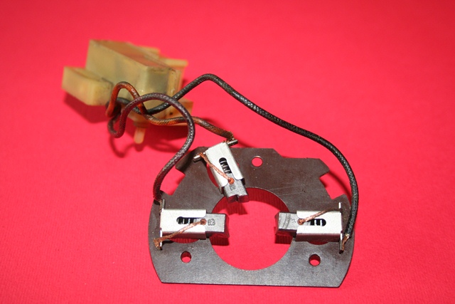
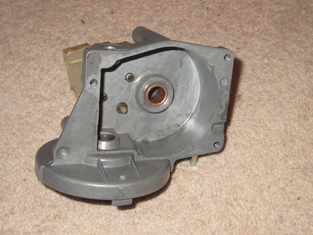
The rebuild starts with installing the armature brushes and parking switch unit, as these are wired together. The brushes are secured by three small setscrews and the connecting wiring passes through a notch in the motor gearbox housing.
The parking switch is secured by two setscrews from the inside of the gearbox compartment, as shown in the middle photo below. This also shows the protruding parking switch plunger which is activated by a cam on the underside of the gear wheel. The cam positioning is such that it operates the switch when the wiper blades return to their normal rest position.
| First fit the brushes | Parking switch attachment | ACF50 applied to Yoke |
|---|---|---|
|
|
|
|

After several attempts at fitting the armature and yoke, I found it easier to first fit the armature into the brushes and motor gearbox and then fit the yoke. With this approach its was necessary to hold the armature’s worm drive from within the gearbox so that, when fitting the yoke, the yoke’s magnets didn’t pull the armature out of the brushes. Also don’t do what I did and forget to fit the plain washer between the armature and motor gearbox housing!
Care was also needed in making sure that the thrust and fibre washers were correctly seated in the yoke bearing housing. The easiest way to do this was to join the two with yoke positioned so the ‘bearing’ housing was facing downwards.
Initially I tried to put the armature into the yoke and then attach them both to the motor gearbox. However the problem was it was then difficult to withdraw the three sprung brushes at the same time as inserting the armature, because the yoke restricted access to the brushes.
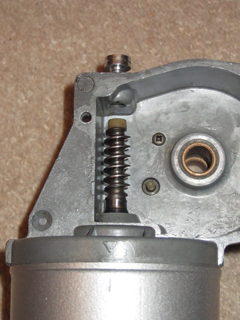
The middle photo below shows the arrow head marking on the motor gearbox and a corresponding line on the yoke. These need to be aligned when refitting. Also shown is the threaded armature stop. This was then screwed into the gearbox housing until it touched the nylon cap on the armature shaft, before being backed off a 1/4 of a turn.
| Next fit the armature | Alignment markings | Belleville washer goes here |
|---|---|---|
|
|
|
|

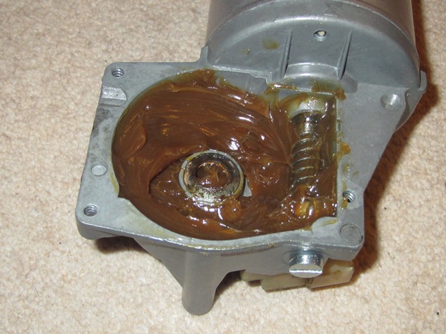
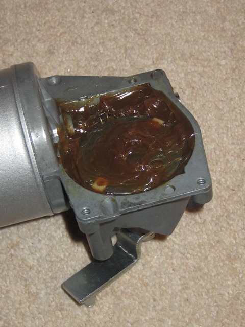
The Belleville washers is then positioned within the gearbox before inserting the geared output shaft. The rest of the gearbox was then filled with grease before the output rotatry link and gearbox lid were refitted. The rubber moulding sealing the output shaft area had hardened and split.
At the time I dismantled the motor, it was one of the few parts that wasn’t being remanufactured. Probably because it was only used on the Series 2. However by the time I has started the rebuild, one of the suppliers had made a small batch so I decided to grab one while still available.
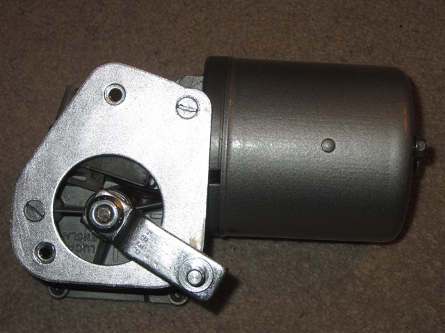
| Re-packed with grease | Output rotary link | Motor rebuild completed! |
|---|---|---|
|
|
|
|

The only thing that remains is to adjust the various wiper motor & rack linkages which can only be done once they’re installed in the car. People usually leave the installation of the windscreen until the latter stages of a rebuild. I guess this is because it would restrict access to dash area. However I’m tempted to install the windscreen as soon as the dash wiring looms and dash panels are in place. Therefore I’ll be able to adjust the linkages before the bulkhead access become restricted.
Sorry, the comment form is closed at this time.