
The ‘refresh’ of the alternator turned into a full rebuild because the rotor’s slip ring needed to be replaced, as it was heavily grooved, and the main rotor bearing had seized. In fact, the slip ring was found to be cracked on the underside once it had been removed. Fortunately all the components needed for a rebuild are still readily available.
 As previously mentioned, the Rootes Parts website covers the conversion of the internal electrics to a more modern, self-energising design.
The revised electronics energises the rotor field winding from the alternator’s output, rather than directly from the battery. This produces what Rootes term a ‘soft start’. When the car is started, the output from the alternator is zero, so a much reduced current flows through the field winding as it is wired in series with the more resistive Ignition Warning Light bulb.
The initial current in the field coil is approximately 10% of the normal operating current. However as the alternator output increases up to a typical 14.3v to charge the battery, the voltage either side of the warning light becomes equal, effectively removing it from the circuit energising the field winding. As there’s no voltage drop across the warning light, it goes out and the field winding is now powered directly from the 14.3v alternator output.
Being self energising also has the added benefit that if the belt fails, the alternator output would fall to zero and the field winding current reduces back to 10% of the normal operating current. Thus avoiding the field winding being burnt out.
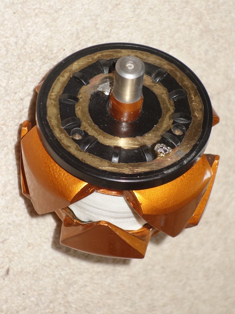
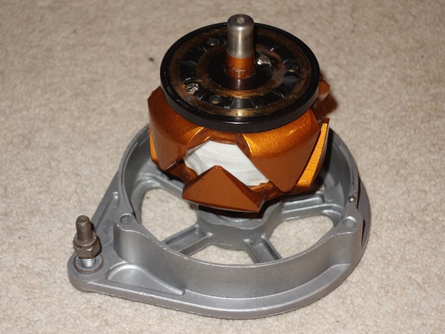
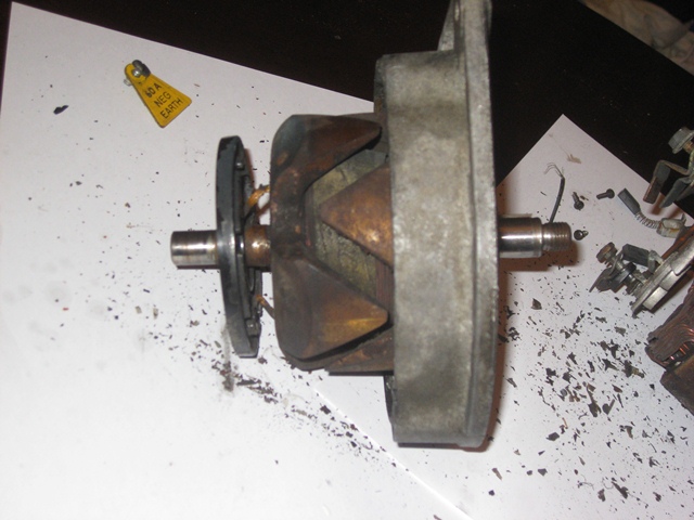 Three screws fix the split ring plate to the rotor. Once removed, the plate can be pulled away from the rotor to reveal the ends of the rotor field winding, which pass through the rear of the slip ring plate and are then soldered at the front to the brass slip rings.
It took a high output soldering iron to melt the solder joints, probably due to the age of the solder, enabling the slip ring plate to be removed.
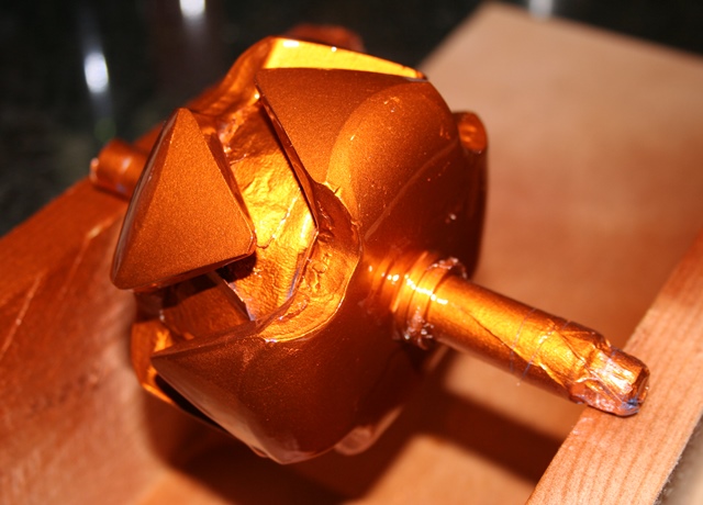
The rotor’s field winding wire is insulated by an enamel coating and then covered by a fibreglass tape so these were protected by masking tape before the rotor was bead blasted, in preparation for painting. The rotor was painted in numerous coats of Burnt Copper and then Clear VHT Engine Enamel paint. VHT paint was chosen due to the high operating temperatures reached and the proximity of the alternator to the exhaust manifolds.
| Painted in Burnt copper VHT | Curing in the oven | Winding re-lacquered |
|---|---|---|
|
|
|
|
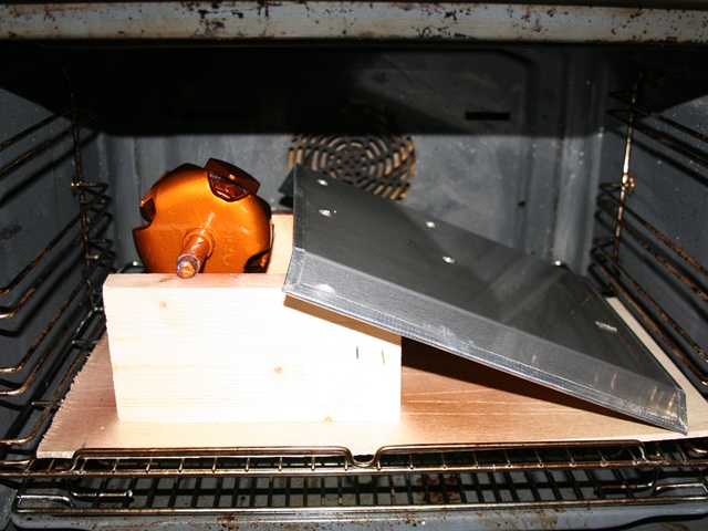
Once the paint had dried, it was cured in the oven at around 100 degrees Celsius for about 45 minutes ….. and, rather sheepishly, the oven then left for a day or two until the aroma had gone! The fibreglass insulation sheaths covering the ends of the field winding had deteriorated and eventually broken free with all the disruption getting the slip ring plate off.
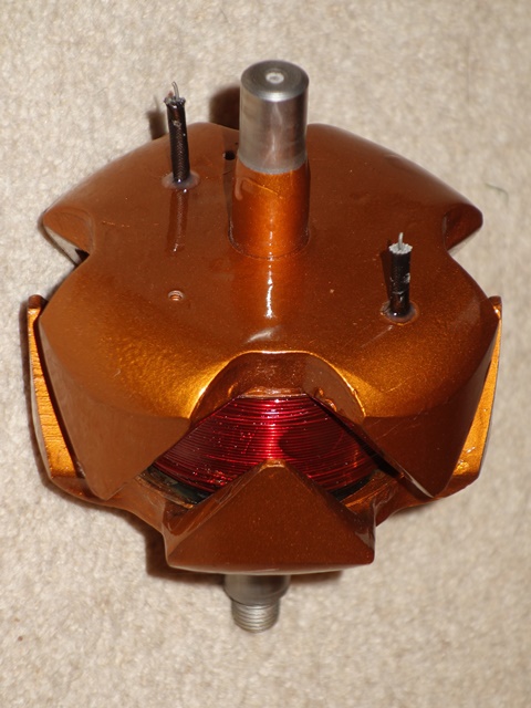
I found an electronics supplier, Brocott UK, who supply the 2mm fibreglass sheathing as well as bottles of motor winding enamel and new fibreglass tape. After the old tape was removed and the winding cleaned up, it was re-coated with a generous coating of enamel. The new sheathing had to be held in place by a small amount of Araldite were it enters the rotor as I needed to ensure the field windings couldn’t short against the rotor body.
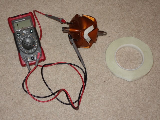
The field winding was re-taped which was a fairly fiddly job, as the 8 prongs of the rotor get in the way. I suspect the winding was originally wound and taped before the two halves of the rotor were fitted together. Before progressing any further, two important tests were made; i) the winding resistance and ii) confirming the field winding wasn’t shorting with the rotor. The winding resistance was 4.2 ohms which is slightly above the recommended upper limit of 4 ohms but I’m happy to leave as is.
| Checking the winding wasn’t shorting | New slip ring soldered and fitted |
|---|---|
|
|
|
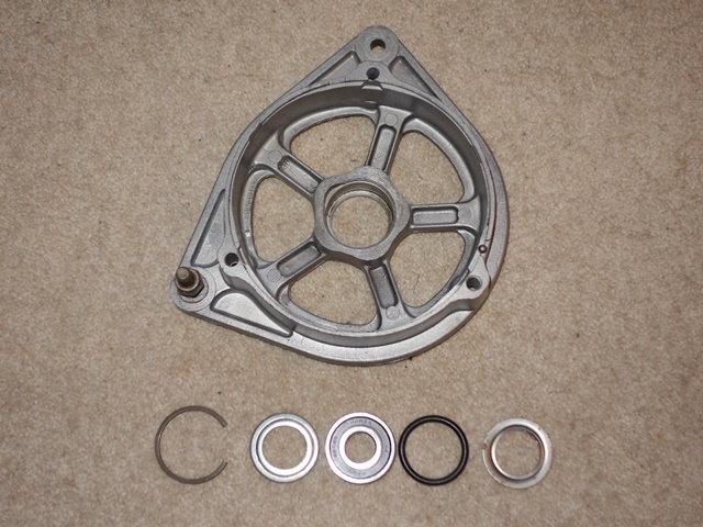
Attention now turned to the fitting of the main rotor bearing. The original had seized and so a replacement bearing kit was ordered. The new bearings are sealed for life units which have a slightly lower maximum RPM. However I was assured they would be fine unless driving at full RPM for prolonged periods.
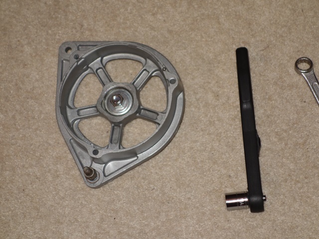
The outer cover plate and then the rubber ‘O’ ring are placed in the front alternator housing before the bearing is tapped into place. Finally the rear cover plate is inserted and the whole ensemble retained in place by a circlip. I couldn’t compress the parts sufficiently to fit the circlip, due to the thickness of the new rubber ‘O’ ring, and had to resort to clamping them between two suitably sized washers using a bolt. With the bearing installed, the rotor was tapped into the bearing with a nylon hammer.
| Parts of new bearing kit | Compressing the ‘O’ ring | Rotor press fitted into bearing |
|---|---|---|
|
|
|
|
It was only at this point that I found a spacer that is clamped between the inner bearing race and the fan & pulley did not fit. The inner diameter of the new bearing cover was too small to enable the spacer to be fitted. So the whole bearing had to be removed and re-fitted using the original outer cover!
Alternator’s internal electronics
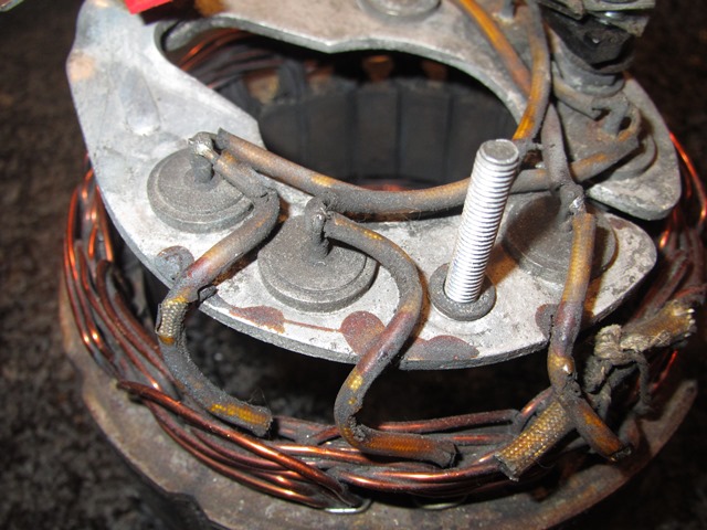 The rectifying diode housing and attached stator were removed from the rear housing by undoing the external nuts on the three terminal posts. Once again I had great trouble de-soldering the joints, this time connecting the stator windings to the diode housing.
The problem is that typical soldering irons, used in electronics, don’t have sufficient output to melt the solder. This is mainly because the relatively large gauged wire used dissipates more heat than the soldering iron can deliver and the diode housing is designed to act as a heatsink.
So I’m now the proud owner of 4 soldering irons, with increasingly higher output ratings! The highest being an 80W iron normally used for soldering stained glass window frames – it was ideal!
The Lucas 11AC alternators use a three-phase bridge rectifier, containing two sets of three diodes, to convert the AC output from each of the three stator windings into DC. Essentially the output of this type of rectifier is close to a DC supply as it is the sum of the positive components of the three AC voltages, which are 120 degrees out of phase from each other.
The conversion involves adding a further set of three diodes to provide an additional DC output to power the rotor field winding. The self-energising alternator no longer requires a 3AW relay so the AL terminal can be re-used for the secondary DC output.
Each terminal post has a variety of insulations and metal fittings – their fitting order was carefully noted as each part was removed to ensure they were correctly refitted during the rebuild, as shown in the photo below.
| Notes taken during disassembly | Parts assembled for the conversion |
|---|---|
|
|
|
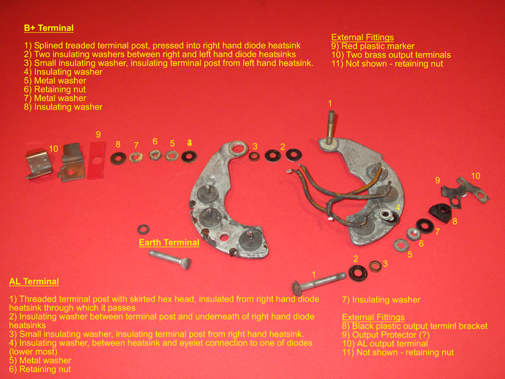

The main points to note are the B+ and AL terminal posts must not short with each other or the alternator casing. With this in mind, the order and purpose of insulators becomes more obvious. The diode housing consists of two halves into each is pressed a set of three diodes. The two halves also act as part of the circuitry as well as a heatsink.
The left hand side is connected directly to the alternator housing via the Earth terminal and provides the common anode connection for the three (negative) diodes. Similarly the right hand side provides the common cathode connection for the three (positive) diodes, which is the B+ output.
The original AL terminal is connected to the wire connecting a pair of the rectifying diodes. This will be replaced during the conversion so the AL terminal is then connected to the output of the three new diodes.
Although the six button diodes look identical, the outer casing acts as the anode for the three inserted into the left hand heatsink (their cathodes being wired to the stator coils) while it acts as the cathode for the other three. Therefore it is essential to ensure they are installed into the correct side of the diode housing. Fortunately most multimeters have a diode test function so it’s easy to check which is which.
The same 2mm glassfibre sheathing for the rotor winding was used to insulate the 16swg copper wire connecting pairs of diodes on each half of the diode housing. Again, the 80w iron made the soldering a doddle. The next step was to install the additional three 6 amp diodes to provide the output for the field winding.
Their anodes are soldered to the anode posts of the positive diodes, delivering the B+ output, and their cathodes are all connected to the AL post. I crimped and then soldered the cathode wires into a 3/16″ eyelet terminal which fits neatly onto the AL post.
| Wiring of the standard rectifying diodes | Additional diodes to power field winding |
|---|---|
|
|
|


There’s not a lot of room between the rectifying diode housing and the rear alternator body so insulation was added to the leads of the additional diodes. Several trial fittings were made to ensure the diode housing did not foul within the alternator body, before finally soldering the diodes in place.
In the meantime the resistance of the stator coils had been checked to ensure all was well before the stator was cleaned up – wire brushing to remove all the rust and then repainting. The stator was then reattached to the diode housing by soldering the coil field wires.
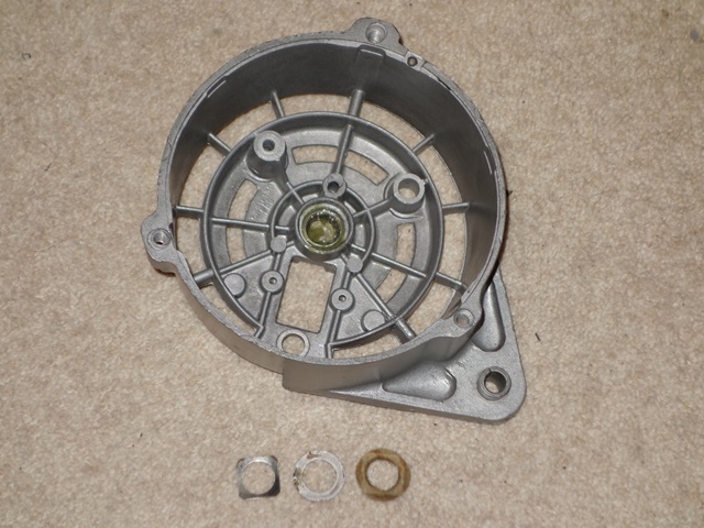
The bearing kit came with both front and rear bearing so the latter was pressed into place and the bearing completed by fitting a felt washer followed by a metal washer and finally a square, spring washer. The corners of the spring washer lock against the alternator housing and hold the other washers in place.
| Rear bearing components | Housing alignment markings |
|---|---|
|
|
|

Two things I wasn’t sure about was whether to soak the felt washers in oil and what grease to use for the bearing. In the end I soaked the washer and opted for a polyurea grease. Hopefully it should be ok! The stator and diode housing could then be refitted to the rear alternator body, taking care to add the various insulating washers.
New slip ring brushes were fitted before reuniting the two halves of the alternator. The two alloy halves have a small dimple marking which both need to be aligned with the narrower and deeper groove in the stator.
The rebuild was completed by fitting the spacer on the rotor shaft followed by the Woodruff key, the cooling fan and finally the pulley.
| Electrical terminals at rear | Front & rear halves reunited |
|---|---|
|
|
|
|
|
|


The only decision left is whether to get the alternator professionally tested off the car or wait until the engine is running …..
Chris,
Stumble don your brilliant restoration story.
Next weekend, I’m going to sit down with several cup of coffee and read my way through i: – it’s bloody brilliant!
Good on you. And thank you for such an informative and interesting account.
Good luck
Wayne
Hi Chris,
Your article on the alternator mods is excellent and very well presented!
I have saved the whole document to my PC ready to absorb at my leisure before I start and modify my own 11AC alternator They are susceptible to surge voltage at engine start up in original spec and I have already gone through three 3AW units! on my S1 2+2
Are you able to give me the specification, part number or any other info in order for me to find a UK supplier and order the 3 x diodes neccessary for the upgrade?
By the way, the reason the soldering is such a pain on alternators is that the solder is high temperature spec and most hobby soldering irons just don’t get hot enough,
Kind Regards,
Art.
Worksop, Nottinghamshire. UK.
Car No. 1E50697
Hi Art,
Sorry for the delay in responding – the restoration has ground to a halt recently due to holidays etc.
I’m glad you found the write up interesting. I was slightly apprehensive of making too many modifications but this one seemed sensible. I’d heard that the 3AW units were prone to failing so, as mine had fallen apart when the car was dismantled, it was a easy way to avoid the issue!
I seen other owners who have fitting modern alternators which have the self-regulating electronic built in but I wanted to keep the 11AC.
I purchased a set of the standard replacement diodes (3 positive, 3 negative) from and the additional rectifying diodes were Radioshack 6amp purchased from T2 Enterprise (I think they were called Tandy).
I thought the de-soldering problems was just due to the heatsink dissipating the iron’s heat too rapidly. But you’re right – after I purchased a high output soldering iron I did spot in the service manual that any repairs should be made with grade M solder (45% tin-55% lead).
I had trouble finding any specification for M-grade or suppliers. The wiki entry on solder suggests that mix of tin & lead should melt at 227 degrees, so I’ve used some solder that’s as close as possible. Fingers crossed! Much of the solder now is lead free and so no good for the alternator.
Regards,
Chris
Your presentation was great; thank you. I love the copper paint and the oven thing. Will anyone ever understand E-Type guys? I am doing my alternator now and would like to put in a new slip ring as mine is quite grooved. Any thoughts for sourcing? Thanks, Steve
Hi Chris,
I’d like to thank you for such a thorough write up and photo logging of the disassembly and re-assembly of your alternator (and indeed the rest of your project). You have just helped me out of problem as I combine two alternators into one for my S1.5 E Type and didn’t record the disassembly! Mine won’t look as smart as yours does but stands more chance of working thanks to your great website.
Thanks,
Ross
stands more chance of working than if I hadn’t read your write up, not more chance of working than yours!
Thanks,
Ross
Hi Ross,
I’m glad the write up was useful. It’s the first time I’d opened up an alternator so it was very much a voyage of discovery. It was a great relief to find out that the internals are quite simple. The only issue is making sure all the little spacers are in the right order so the B+ and AL terminals are insulated from the housing.
I’ve not come across like for like main bearing so I’m just hoping the sealed for life ones are up to the job.
Regards,
Chris