
Time pressures delayed the full electrical shakedown testing until after the engine was up and running. Power is only required to the ignition and fuel pump circuits to start the engine so all the other fuses were removed. Having said that, I did end up fitting the fuse for the instrument voltage regulator in order to obtain oil pressure and temperature readings while the engine was running.
The other fuses were now fitted in turn, stopping to test each of the components they fed, before moving on to the next fuse. The resulting snagging list was encouragingly minor:
- The main beam can’t be flashed from the indicator stalk
- The original hazard flashing unit is on the blink!
- The brake fluid warning light isn’t coming on
- The wiring to the rear brake and sidelights have been crossed over
- One of the cooling fans is a little noisy and spins the wrong way!
- The heater fan is making contact with the housing
- Neither the washer or wipers work
- Only one horn worked
Overall I was quite pleased with that for a first test. Especially as it was the first time the cooling fans and wiper motor had been tested since I rebuilt them and the washer, wiper, brake fluid warning light and horn were all simply missing earth connections. So easily solved.
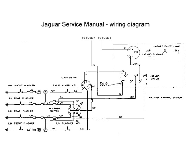
Indicators and hazard lights
There was a fair amount of head scratching when wiring up the hazard warning light switch. The part number identified it as a hazard switch from an XJ6 and its pin connections conflicted with those in the Illustrated Parts Manual!
| Hazard wiring diagram | Hazard switch wiring |
|---|---|
 |
 |
So I attempted to go back to first principles (or my understanding of them!) to work out the correct wiring. The one thing that was puzzling me was why separate indicator and hazard flasher units were used. They are essentially performing the same role – converting a constant DC supply into a square wave, with a suitable duty cycle to provide the correct flash duration and frequency.
The light bulb moment came when reading the requirements to pass an MOT. The hazard lights must be able to operate without a key in the ignition while the indicators are only powered when the ignition switch is on. The other difference is the power rating as the hazard unit needs to draw more current drive both sets of indicator lights at the same time.
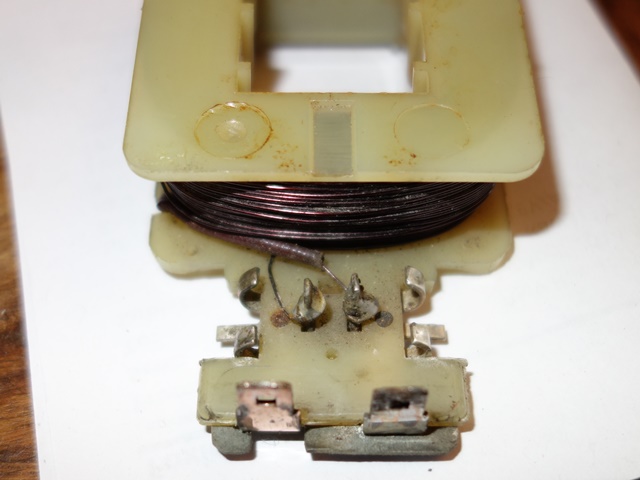
The duty cycle of the unit is achieved by a bimetallic strip which expands and contracts depending on whether current is flowing. When the indicators are on, the current generates heat in the two metals, which expand at different rates. This causes the strip to move away from its contact and break the circuit. Without a current, the strip rapidly cools and the circuit is re-established allowing current to flow once more and the process to repeat.
Therefore the flashing frequency or ‘duty cycle’ is directly related to the rate of expansion/contraction of the bimetallic strip, which is a function of the current flowing. This is why modern LED indicator bulbs often do not work on classic cars as they draw far less current and therefore may not generate sufficient heat to switch the traditional units. Modern transistor based units are available to overcome the problem.
Therefore the switch needed to have the following connections:
Hazard switch in OFF position
- Indicator flashing unit is introduced into the circuit (the two green wires are connected)
- Hazard flashing unit is cut out of circuit (connections between the LGN, GR & GW wires are broken)
- The indicators can then be operated via the switches built into the indicator stalk
Hazard switch in ON position
- Indicator flashing unit is cut out of circuit (by removing power to its green wire)
- Hazard flashing unit is introduced (by connecting its LGN output to both the GR & GW indicator feeds)
The only problem was the random frequency of the hazard flashing which was easily solved by fitting a new flasher unit.
Cooling Fans
The S2 cars have an otter switch to turn on the cooling fans at its rated temperature and requires a special connector, which has been on back order for ages. A spare dash switch was rigged up in its place so the fans could be switched on and off at will, which would be useful when testing and tuning the engine. The first fan spun up and ran smoothly and quietly, which was very pleasing, as they hadn’t been bench tested after their refurbishment.
However the operation of the second fan was noisier because the blade was not quite square on the armature shaft, causing vibrations. Removing it was a fiddly process with the engine bay completed so I was cursing not having bench tested it!
But more importantly, the motor was rotating the wrong way, pushing air forward towards the radiator rather than drawing air through it. Its effect would be worse than having no fan at all. When travelling at speed there would be a natural flow of air through the radiator. Having a fan blow against this flow would reduce the cooling ability.
It is rather odd because reversing the supply polarity of series wound DC motors (and indeed shunt wound motors) does not reverse the direction of rotation. The only way to rectify this would be to reverse the connections on either the field or the rotor windings (but not both!).
The rotating force (torque) on the armature shaft is the result of the interaction of the magnetic fields of the armature and the field winding – opposite poles attract, like poles repel. The directions of these magnetic fields are dependant on the direction of the current following through them.
Therefore changing the polarity of the power supply does not reverse the direction of rotation because both the field and armature currents will be reversed and therefore both magnetic fields. A double negative if you like, that cancels each other out!
The only practical option for these Lucas motors was to reverse the field winding, which was a very simple job.
| Field wires just needed swapping | All sorted – an easy soldering job |
|---|---|
 |
 |
The fan now rotates in the correct direction to draw air rearward through the radiator. The fan was also re-seated to stop the fan vibrating so much.
I was trying to fathom an explanation as to why the motors were rotating the wrong way and then recalled that I had difficulty dismantling the two motors I’d acquired many moons ago, at the start of 2012. They were of the same design but had the fans mounted the wrong way round.
The person had indicated they were selling them as they had upgraded to modern fan units. However I suspect they had sourced motors from a different vehicle and noticed they were turning the wrong way. They had then mistakenly concluded mounting the fans the wrong way round would rectify the situation, rather than just improve their efficiency in making things worse!!
Wiper motor & Intermittent module

Intermittent control above
brake warning light
I’d decided to fit the Hella intermitted wiper module that other E-Type forum members had advocated. It works independently from the two speed wiper switch on the dash and the modification is reasonably discreet and reversible. The intermittent control uses the hole in the dash for the rear window heater on the FHC, which is blanked off on the OTS cars.
Like the hazard warning switch, the part number on the wiper motor switch also suggested it had originally come from an XJ6. The problem was the connected terminals were different to the correct switch (OFF 5-7, Normal 4-5, Fast 2-4) and so it was another case of trying to work out how it should be wired.
The combination of common sense and trial and error eventually produce the correct operation, which differed from the wiring suggested by the forum post. I’ve wired intermittent module into the ULG feed rather than the suggested YLG wire, which is for operating the motor at high speed.
At the same time, I also decided to add a jumper lead (with an inline diode) from the washer switch to the slow speed supply to the motor. Therefore the wipers now operate automatically while the washer switch is pressed. The diode is needed to stop it working in reverse, with the washer operating when the wipers are switched on!
Heater Motor
A complete new heater unit had to be fitted as the original had largely rusted away. The resistor, providing the dual speed operation, is riveted to the base plate of the heater motor. I’d foolishly assumed the new units would be supplied complete with the resistor already attached – dream on!
The resistor is sold separately and, due to the lack of clearance, requires the base plate to be removed from the motor in order to fix it. The wires are then soldered to the resistor rather than via spade connectors. As a result, the loom has bullet connectors built in, approx 6″ from the end of the wires, to allow the motor to be separated from the loom if it needs to be removed for servicing.
| Resistor provides 2-speed operation | Loom wires are soldered in place | Fitting was tricky due to the engine frame |
|---|---|---|
 |
 |
 |
However the looms didn’t come with the rather crucial two wires needed from the resistor to the motor terminals! The other issue came trying to re-fit the motor to the heater housing which had already been attached to the bulkhead. Removing it wouldn’t be an easy option as the cooling system had now been filled.
The reason the motor and fan cage couldn’t be fitted onto the housing was the base plate fouled on the engine frame. It was necessary to detach the fan cage from the motor by undoing the clamping grub screw. This allowed the cage to be fed up into the housing and then reconnected to the motor once the motor was clear of the engine frame.
The fan just had to be re-attached ever so slightly nearer the motor to cure the fouling problem found during the initial shakedown tests.
Alternator testing
The electrical component that I’d been putting off testing was the re-wired alternator. The modifications to the alternator were more far reaching than any of the other electrical work and so there was more scope for things to go wrong. Once all the other electrical issues had been resolved, I fitted the alternator belt and prepared to start the engine. Would it work or would it blow any of the other components?
Unfortunately I didn’t have a suitable ammeter to measure the theoretical maximum output of approx 60 Amps and so my testing was limited to measuring the voltage at the battery terminals with a multi-meter:
- With the engine off, the terminal voltage should be approx 12.7v
- When running at idle, the alternator should raise the terminal voltage to around 13.9v-14.3v
- The terminal voltage should reach between 14.3-14.6v running at 2500 rpm
In theory if the alternator output drops from the last two levels then it points to the failure of one or more of the rectifying diodes. If it rises above 14.8v, then the 4TR voltage regulator unit is not limiting the maximum voltage and needs to be replaced to avoid overcharging the battery. However I also have to consider that any lack of output could also be due to the additional diodes introduced to self-energise the field winding.
It was a welcome anti-climax that the initial test appeared to be successful. Although I’ll need to do further checks to ensure it’s charging when the car is run for a longer period.
Hi Chris
Good to see your blog active again after 6? months. I was starting to think you might have had coil problems, as with mortal coils for the shuffling off of.
Rare to see electrical principles described coherently in respect of classic vehicle electrics (I am an electrical engineer).
My own 1969 opalescent datk blue OTS is proceeding at snail’s pace. I am having it restored so I am concentrating on getting the body ready for the next 45 years and the IRS cosmetically sorted, deferring cosmetic jobs on fan motors, alternators etc. to the future. Bits that can be removed fairly easily that is. Don’t want to add anything to delay the process, it could be two years between joining the owner’s club and driving one.
Maybe we will get to can park opalescent dark blue SII OTSs side by side at the club day in July, which should showcase how your meticulous detailing really makes a difference, especially with the bonnets open.
Steve
Hi Steve,
No, I’m still going strong although recently not on the restoration! It lost momentum over the summer due to a couple of long holidays and other commitments.
I’d also hoped to get it through the MOT by late September (without any trim) but it was a case of one step forward and two back for a lot of the remaining tasks. Once it became clear September would be missed, I decided a more realistic date would need to be in the Spring, after the road salt has gone. Hence the urgency was lost. Now I’m back from holiday it should be full steam ahead.
It’s been quite enjoyable finding out how all the electrical components work – at least they can be taken apart to repair, unlike modern units. Hopefully it should help in the future if (read when!) problems arise.
It would be good to get the two cars together – I’ve not come across too many ODB cars, especially S2s. The OSB and Gunmetal colours seem to be in vogue at the moment but I like how the ODB can appear quite blue through to a greyish blue depending on the light.
All the best with your refurb/restoration!
Chris
Hi Chris, great work here on all fronts!!
Just starting my restoration of a 1969 FHC so living on your website at the moment. This is my first step into the world of classic car restoration so going in a little blind.
Would be great to pick your brains at times if I may? Certainly when it comes to painting, powder coating and plating parts.
Thank you.
Hi Jason,
I’m glad your finding the blog of interest and if there’s anything you need to know just let me know. If you’ve not already come across it, the E-Type forum is a great place for advice and help: http://forum.etypeuk.com/
Good luck with your restoration. I started mine in a similar position as it was really my first venture into a major classic car restoration. I quickly realised that the bodywork and painting was beyond my skill and so best left to the professionals. The rest has been a case of learning as I went.
Also take as many pictures as you can when you dismantle it. Mine was taken apart before I had a digital camera so I only had a handful of photos to remind me. The Illustrated S2 parts book was also really useful – most of the S2 diagrams have now been adopted on the SNG Barratt website.
Chris
Chris
I was looking at some recent club magazines where it was noted in an article that the Series 2 fans rotated ‘in the opposite direction’. That confused some readers who took this to mean that they should run in the opposite direction to one another on the same car. The author actually meant that they rotate in the opposite direction to the fans in a Series 1, so maybe you have one Series 1 fan motor. Are they similar? I don’t know.
He also said that it is important to get the polarity correct or they will rotate backwards, so he still hadn’t quite got it.
Steve
Hi Steve,
Thanks for the information. It sparked me into delving a little deeper and it’s starting to make a bit more sense.
The S1 & S2 fan motors are the square bodied type and, externally, look identical. However the motor part numbers changed: C16452 for the S1 and C28133 for the S2. I’m now fairly sure this must have been due to the different internals so they rotated in the opposite direction. The motors changed to round bodied ones for the S3 – as my car came with one square and one round motor.
The club magazine article does sound correct in that the Series 2 fans rotate in the opposite direction and, as you point out, opposite to the series 1 rather than side to side.
I found a photo of the S1 set-up on another restorers blog where you can just make out the leading edge of the S1 fan. It must rotate anticlockwise (when looking forward from the cabin) to draw air rearward:
The S2 fans need to rotate clockwise so I must have acquired two motors originally from a S1 or another vehicle. At least that explains it now!
I’m sure I’m correct that the polarity doesn’t matter. When I noticed it was turning the wrong way round, my initial reaction was to change the supply polarity. Without success!
It then dawned on me it was because it was a typical series wound motor.
I think the only way changing the polarity would reverse the motor is if the stator had been a permanent magnet rather than an electro-magnet. I’m sure all the old square bodied Lucas motors were the latter.
Chris
Hi Chris
Are you actually driving it yet? Lovely day today, and I saw a lovely BRG S2 OTS in Ickenham while riding to the Ace cafe on my BSA. Must write to the Times.
My S2 is inevitably turning into pretty much a full on resto in spite of my good intentions to just go for something pretty and reliable. Not to the same level of detailing as yours though.
Anyway I find that I also need to press an old S2 fan motor and an S1 motor into service to downgrade from a Kenlowe conversion (a step which I obviously might come to regret!).
Do you have any tips on techniques for polishing up the end plates? they look like aluminium alloy or Mazak to me.
Steve
Hi Steve,
I’ve only driven it up and down the driveway so far – the MOT is booked straight after the bank holiday. Then it’s off to have the engine tune on a rolling road and get the hood fitted.
Ah shipwright’s disease! I know the feeling. Once you put back a refurbished part it makes the surrounding components look worse. when I finish mine the intention is to take on tours rather than cosseted.
I knew other owners had reported poor cooling with the standard set up and the advantage of moving to the Kenlowe fan. Although I suspected many of these were probably owners of the earlier cars, before the twin fans. That’s why I decided to keep as standard for now and will only convert if it becomes a problem.
I had my end plates ultrasonically cleaned by a guy operating as ‘Carb Cleaning’ just outside of Guildford. I batched up all my alloy parts from things as small as the end plates all the way up to the bell housing for him to clean and they came up almost as good as new. Otherwise I would got for the softest bead blasting (soda or walnut shells).
Chris
Chris
Good to hear that you will be touring with yours too. We plan to take on the northern spain tour next year.
I think I will try a 2 litre home ultrasonic tank so that it is always available for little bits & pieces esp Amal carbs.
I am hoping that overheating in Texas and California doesn’t necessarily mean overheating in Yurp.
Steve