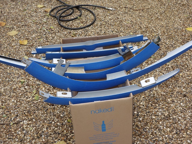
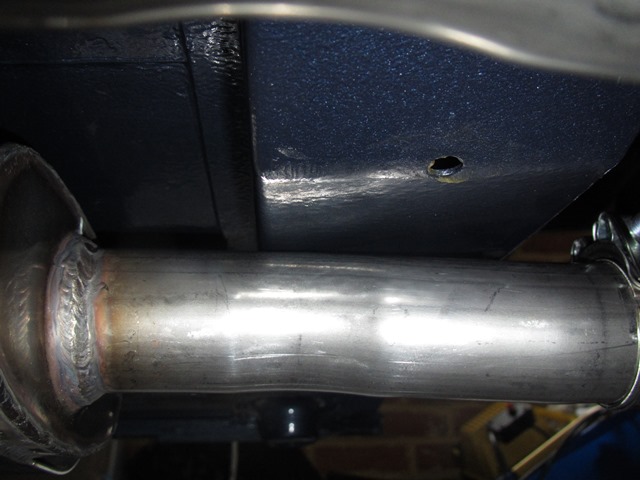
Chris

Jun 152014
 

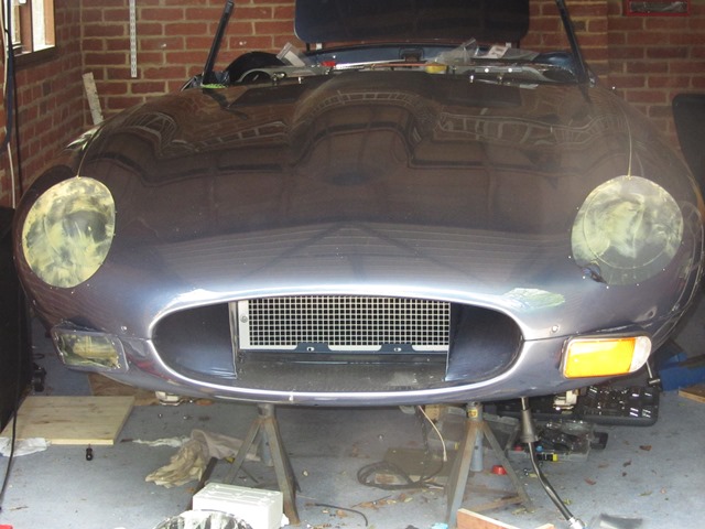
Before the headlights can be fitted, the bonnet electrics need to be completed while there’s still access.

The addition of headlamp relays had been made and so all that remained was to run the bonnet loom from the 10-way connector mounted behind the LH headlamp ‘sugar scoop’ to a 5-way connector behind the RH ‘sugar scoop’.

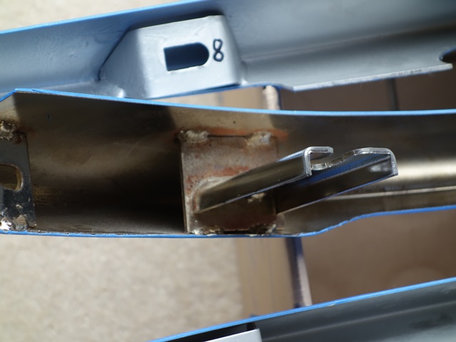
A small square bracket should secure the 5-way connector and is located on two studs welded to the bonnet. However the stud centre-to-centre spacing was 3/16″ wider than that of the bracket and the holes in the bracket were too small. Yet more cursing of repro parts!

My initial thought was the bracket was incorrect but that wasn’t the case. The problem was the stud spacing on the bonnet manufactured by the Jaguar Daimler Heritage Trust. It’s a bit worrying if they can’t even get their own bonnets right!

So the fitting of the front indicators and headlamps was delayed until I was able to fabricate a new bracket.

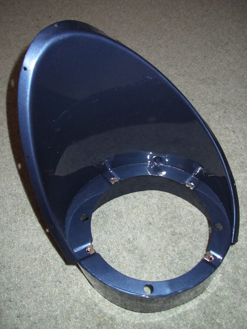
In the meantime I set about the relatively simple task of building up the headlamps in the sugar scoops. The original bowls were on the cusp of being salvageable but, for the relatively small cost, I opted to fit new ones. The first two sets of bowls supplied by SNG Barratt were wrong – the first didn’t have a spring attachment and the holes in the second didn’t align with the holes in the scoops. How hard can this be?

The third set didn’t fit either but the ‘only’ differences appeared to be additional brass fittings on the rim of the bowl and a slightly different location of the lug for the retaining spring. Enough was enough, I decided to use these bowls and removed the offending brass attachments with a Dremel.

(Once the parts are correct) There isn’t anything difficult fitting the headlamp components and everything is self-explanatory.

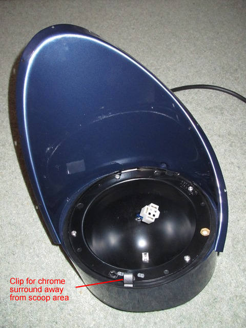
Spire nuts fitted to secure the bowls Then the rubber gasket Orientation of headlamp bowl

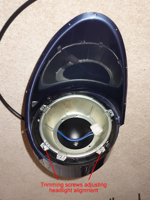
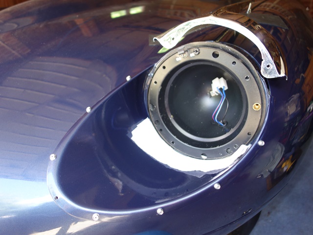
With the bowls in place, the headlight seating rim can be fitted. The rim is attached to the bowl by a retaining spring and two trimming screws. As their name suggests, the latter are adjusted to alter the headlight alignment; one vertically and the other horizontally.

Note: the photos below were taken before I’d realised the bowl, and therefore the adjustable seating rim, needed to be rotated anticlockwise by 90 degrees. The trimming screw to adjust the horizontal alignment needs to be on the offside of each lamp for right hand drive cars.

Next the headlamp seating rim Headlight alignment adjusting screw

Kits containing all the components used for the headlamps alignment are available. However the lugs in the new bowls, to attach the spring, were right at the base of the bowl and noticeably shorter. The replacement spring would not reach the headlamp seating rim. Therefore progressively longer springs had to be tried until one fitted sufficiently well and with enough oomph to handle the likely forces due to the weight of the headlamp.

Standard short spring The numerous springs tested
Finally one fitted! Almost there ….

It is then simply a matter of connecting the lamp and securing it with the retaining ring. Protrusions on the circumference of the headlamp align with depressions in the seating rim ensure the headlamp will always be orientated correctly.

All the electrical connections within the bonnet were given yet another final connectivity check (paranoia – moi?!?) as there’s no access once the sugar scoops are in place. The bullet connectors were also treated to a good coating of Vaseline to help delay any corrosion.

Fixing the sugar scoops
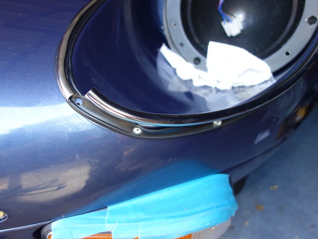
The sugar scoops are fixed to the bonnet by special rivets, which are essentially a standard rivet with an aluminium cup under the head. The cups provide a method for mounting chrome finishing beading, which clips on to the cups to improve the aesthetics by hiding the rivet heads.

A spacer washer is also fitted under each of the rivet heads to raise the cup away from the bodywork to allow a rubber strip to sit under the chrome finishing beading.

Originally a single washer was used although others on the E-Type forum have reported needing two washers to get the trim to attach. I guess this will just depend on the relative thickness of the replacement washers and rubber strip.

They also confirmed that the rubber strip originally had holes punched into it, which allows the rivets and spacer washers pass through it in order to sit flush against the bodywork. I had incorrectly assumed the rubber strip also formed part of the rivet ‘sandwich’.

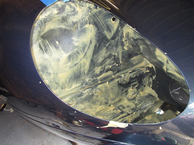
Another suggestion was to Waxoyl all the mating surfaces prior to riveting. I still needed to Waxoyl the bonnet gaps along the front wings before fitting the fitting the chrome beading. So I decided to get this messy job out of the way in one hit and, while I was there, give the areas behind the sugar scoops another thick coating for good measure!

Waxoyling the bonnet-wing gap Rears of sugar scoops 2nd coating for enclosed area

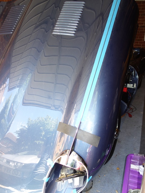
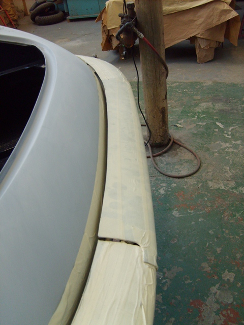
The bonnet gaps for the beading were taped above and below in a futile attempt to avoid a major clean up afterwards. This time the Waxoyl container was sat in a bath of boiling water so it became more a job of pouring on rather than brushing on! The bonnet gaps are now well and truly filled with Waxoyl. Although I might come to regret this if (read when!) it starts to melt due to the heat of the engine!

Position of 5-way connector bracket Masking fit for a rivet!

The paintwork surrounding the sugar scoop area was given the usual riveting protection, a few layers of 3M masking tape, to avoid any damage when the pin snaps off. My plan was initially to use one washer under the rivet heads, as listed in the parts manual. If it was too difficult to fit the chrome finishers I’d have to drill out the rivets and re-do using a second washer. So additional rivets had been ordered just in case.

It was just as well spares had been ordered, as I was soon drilling out all the newly attached rivets to re-do it. Although not to fit additional spacers! I’d been on a riveting roll …. and had been a tad overzealous in their application. The clip to hide the joint between the two chrome finishing strips is held in place by a self-tapping screw. A self-tapping screw that requires a rivet sized hole … well, one that was now occupied by a rivet! What a clot!

Still blissfully unaware of my error! Eyebrow fitting needs the bowl out Dooh! ….a rivet too far!

I only noticed my error as I was standing back admiring how well I’d managed to get the rubber and chrome strips to fit. To make matters worse, somehow the offending rivet had ballooned on both sides of the body panel and couldn’t be pushed through. It required the whole scoop to be removed to sort it out.

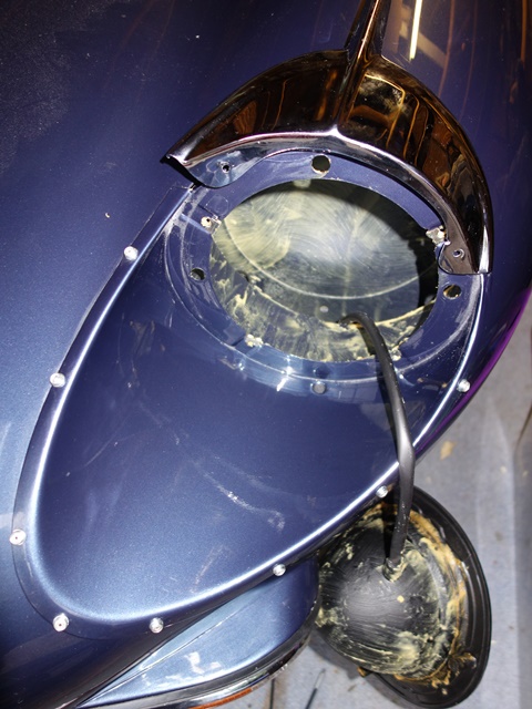
Soon after, I also realised that I’d been a bit premature fitting the headlamp bowls and fittings. The front of the chrome ‘eyebrow’ is fixed directly to the scoop by two self-tappers, behind the headlamp bowl and rubber gasket. As it was a new bonnet, the holes for the screws hadn’t been drilled and so all the lamp fittings had to be removed to gain access.

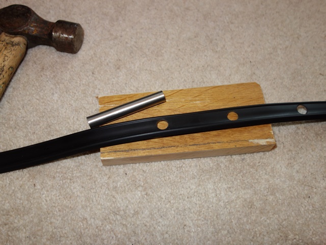
Let’s have another go! Punching holes in the rubber strip

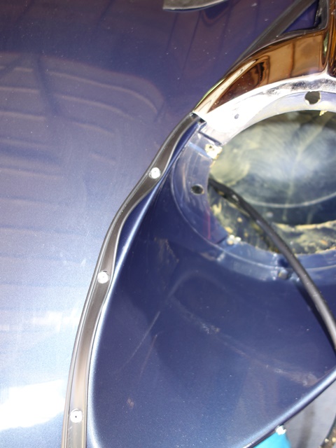
The scoop was re-riveted to the bonnet for round 2! The single piece rubber strip runs around the edge of the scoop with its ends tucking under the ‘eyebrow’. The holes for the rivets had been created by using a length of stainless steel pipe with a diameter marginally larger than the spacer washer. The thickness of the end wall was ground down to create a sharper edge so it could be used as a punch.

The original rubber strips were shaped so there were different part numbers for each scoop. Unfortunately the replacement rubber comes in straight lengths so it tends to ruffle up as it’s positioned around the curvature of the scoop. It’s not much of an issue apart from around the tip of the scoop, where the curvature is tightest. A heat gun helped to persuade it into shape but I cheated by cutting out a small wedge on the inside edge where a hole had been punched and superglued it back together.

I’m sure there are many methods to fit the bonnet chrome but the one that worked for me was:

  • Position the ‘eyebrow’ until it is almost fully home (around 1cm proud of the front wing joint)
  • Hook the rubber strip over the rivet heads and feed under the ‘eyebrow’
  • Slide, rather than clip, the chrome beading onto the 2nd from top rivet head
  • Keep sliding it up on to the top rivet head and then on, until its end is just under the eyebrow. The rubber strip protects the paintwork but care was needed to ensure, if it did suddenly come off the rivet head, it wouldn’t gouge into the paintwork!
  • For the remaining rivet heads: the beading has sufficient flex to allow it to be twisted so it fits fully over one side of the rivet head, before pressing it until it clips over the other side
  • The front of the eyebrow could then be pressed down firmly to spot the correct positions for fitting the self tappers.
Slight ruffling wasn’t an issue But surgery was needed around the tip Re-chroming had distorted the beading

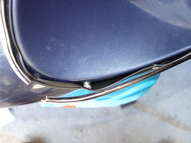
My intention was to fit the long bonnet beading with about 3/4″ extending under the end of the eyebrows. Obviously this required the beading to be fitted before the completion of the headlamps. The only issue was ensuring the brass clips to secure it were positioned away from the bolts clamping the wings to the centre bonnet panel. The gap between the bonnet panels had to be ease open for some of the clips to allow them to slide through.

Easing apart the beading
gap from below
Pressing the beading home
… v carefully!
Rod inserted into beading
to stop it lifting
Fitting the bonnet beading: access from below was needed to ease apart the flanges of the centre bonnet section and the front wing

However extending the beading stopped the eyebrow from being pushed flush against the bonnet. In the end I settled for a butt joint and cut off the extra 3/4″ but adopted another suggestion from the forum: slide a 2-3″ length of small rod into the centre of the beading, leaving of half its length protruding. This engages under the end of the eyebrow but doesn’t stop it being pressed against the bodywork. The rod should stop the end of the bonnet beading being caught and bend out of shape.

Fitting the scoops was a really fiddly job as I’d expected and, with the various problems encountered, took almost an entire weekend to fit the first headlamp (which was the easier of the two!).

I’m still struggling with the second headlamp. The main problems were the dire positioning and alignment of the rivet holes in the scoop compared to the bonnet aperture and the angle of the flange on the scoop.

A shocking gap using the pre-drilled holes The marker pen shows the how far out they were
(and it’s the further of the two marker points!)

The front of the driver’s side scoop was 5-6mm away from the bonnet panel using the pre-drilled holes. A gap that couldn’t be closed by applying pressure as the underside of the scoop was hard against the bonnet aperture. The only solution was to drill a second set of holes. Also the flange angle down one side was such that it couldn’t fit flush against the bonnet panel. The knock on effect was the ‘special’ rivets weren’t long enough to reach through both panels and longer rivets had to be ordered.

The second headlamp was successfully riveted into position using the newly drilled holes. I was both pleased and relieved and had expected that that would be the end of my headlamp woes. Far from it! I couldn’t get the chrome beading trim on with just a single spacer washer. Reluctantly I decided to drill out rivets and start again using 2 washers per rivet.

Again the rivets wouldn’t push through once the head had been drilled off. They felt as though they were embedding themselves into the lower panel.

The headlamp was subsequently re-attached using 2 spacers washers under the head AND a washer under the rear. This was to give the blind part of the rivet something firm to compress against so, fingers crossed, they’ll be easier to drill out in future!

The problem wasn’t the number of spacer washers but the shape of the beading trim. I’m certain they had been distorted during the re-chroming as polishing puts a fair amount of heat into quite thin material. It’s not easy to fettle their shape to fit once the chrome plating is on. They can be rotationally flexed but not re-bent to match the scoop contours.

The chrome beading fitted poorly with noticeable gaps caused by forcing the beading to clip onto some of the rivet heads. In fact the addition of two spacers made these gaps worse, allowing the rubber strip to move underneath. This time I’d spent a further weekend ‘not fitting a headlamp’! Rather disheartened, I’ve given up for now and will have another stab once my enthusiasm is restored!

At least one headlamp is in!

One they are completed, it will be a job I hope not to have to repeat and I’m now questioning the wisdom of the positioning of the inline fuses for the headlamp relay modification!

May 292014
 

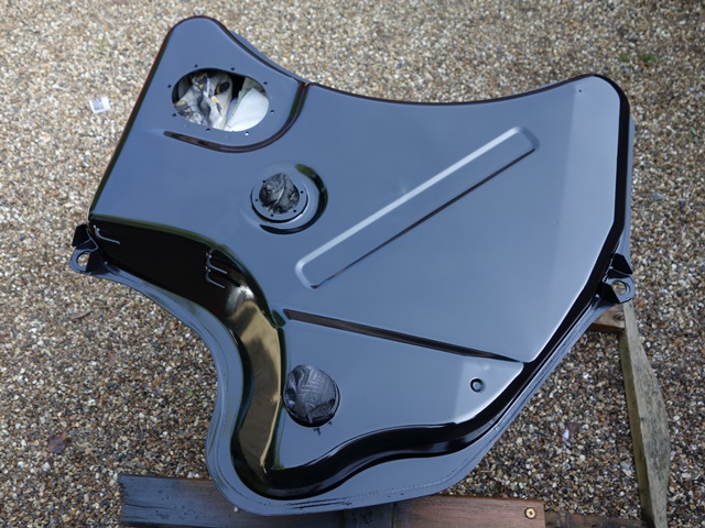
The cars left the factory with untreated fuel tanks and so rusting from within was quite common. I wanted to seal the inside of the tank but needed to ensure that it was not of the PVC type, which is susceptible to hardening and cracking due to the increased percentage of ethanol used in modern fuels.

The other issue was avoiding the sealer blocking the small vent tubes again. Initially I’d looked at hot-dip galvanising but, after this was discounted, it came down to a choice of tank sealers from either KSB or POR-15. These both follow the same three step procedure; de-greasing, metal preparation and then application of the sealant.

In the end I opted for the KSB Gold Standard sealant. Although, oddly, the quantities sold are aimed more towards the motorcycle market. The tank needs to be rotated and rolled during all three stages of treatment to ensure all the surfaces are covered, including the baffles. Therefore it needs to be sealed to avoid leaks.

I didn’t want to ruin the final cork gaskets and so made up some silicone ones, using the left over two-part silicone used to create the mould for the heater vane.

Making silicone gaskets Masking tape retained the silicone Fuel sender gasket

The cover plate with the tube down to the fuel filter could be masked fairly easily to stop it being coated with sealant. Therefore it could be used to seal its hole in the tank. However the fuel sender couldn’t be masked effectively. So, to coating the moving and delicate parts, an aluminium disc was knocked up as a replacement.

Sealing the filler neck was slightly trickier as I couldn’t get hold of a large enough bung. A replacement bath plug from B&Q just about did the job, requiring some additional help from duct tape.

The KSB tank sealer is reasonably fluid which allows it to cover the internal surfaces fairly easily. As a result I concluded that periodic blasts of compressed air would be sufficient to stop the internal ends of the vent pipes from blocking.

Compressed air to clear vent tubes Sealed tank with de-greaser and metal prep Finally the sealant is applied

The first stage involved applying a warm diluted solution of KSB’s AQUA product to thoroughly degrease the tank. The tank then needs to be rinsed and completely dried throughout before applying their ‘Rust Buster’. Again, this needs to be rinsed and the tank completely dried before moving on to the final stage of applying the sealant.

The AQUA and Rust Buster are essential just a branded degreaser and a phosphate acid solution, to convert any surface rust. Therefore cheaper alternative options are available for these steps.

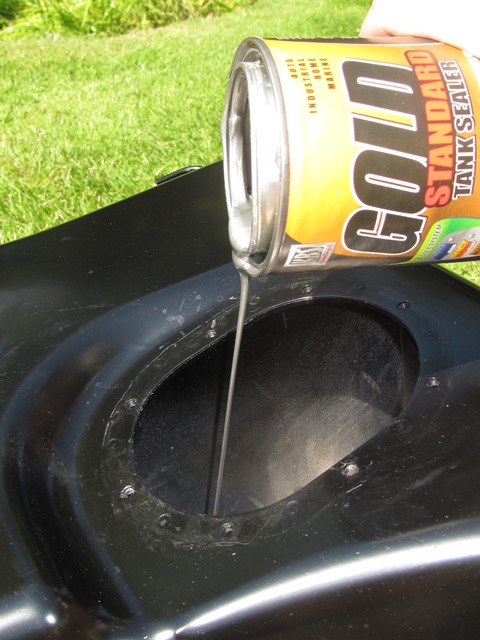
The Gold Standard tank sealer was then be poured into the tank and the tank slowly rotated to ensure all the surfaces are covered. A slow methodical approach to rotating the tank was definitely better than trying to shake the tank. The curing process doesn’t start for at least 30 minutes when it slowly becomes more viscous so there is plenty of time to get good coverage.

Compressed air was periodically blasted down the vent tubes to stop them blocking as well as every time the tank was turned. After about 30 minutes the unused sealant was drained from the tank before it started to thicken due to the curing process.

All surfaces need a light coating Draining the excess tank sealant Repainting the exterior

Unfortunately the various seals weren’t water tight so some phosphoric acid escaped over the painted exterior finish. The weak acid left light run marks in the paint which could probably have been polished out but I decided to repaint the tank with some POR-15 gloss chassis paint.

The completed tank sealed and re-painted
May 262014
 

The weekend had been chosen for attempting to start the engine and the usual additional help was sought, although this time only John from the E-Type International Rescue team managed to secure the necessary leave of absence.

However, before any attempt could be made, there were quite a number of tasks that still needed to be completed; seal and fit the fuel tank, finish off and test the wiring, connect up the battery, connect up the EDIS Megajolt electronic ignition and complete the Mangoletsi throttle linkage to name but a few. Retrospective posts covering these will be added shortly.

The pressure was on! The sealing and painting of the fuel tank was only just completed in time to enable the tank to be fitted the day before. Although I hit a major snag …. it didn’t fit! The mounting points didn’t align with those on the body! The solution was to leave it in place and just connect up the fuel lines for now. It will have to be sorted at a later stage.

The time lost in trying to fit the tank resulted in the wiring and battery tasks not even being started by the morning of the starting attempt. Therefore the fuses for all the non-essential circuits were removed to limit the amount of testing/checking required before starting the engine.

I had permanently wired in a connection for my CTEK battery charger, which has a ‘supply’ mode delivering 13.7v. In this mode the maximum current that can be drawn is limited, enabling the circuits to be tested more safely.

The charger was connected, the ignition switch on and, much to my relief, the fuel pump ticked into action. Rapidly at first and then settling into a slower rhythm.

Moments later, fuel started leaking in numerous places in the engine bay! Power was swiftly cut and the leaks addressed in turn. The first was the fuel line connector which had gone in cockeyed into the filter housing. The fuel inlet pipe was slightly too short which had resulted in the misalignment and cross threading. The only remedy was to re-tap the thread.

The only taps I had were of a dubious Chinese origin that I had been advised were best stored in a bin! Where they now reside. Fortunately we were able to make an emergency trip over to the rather well equipped McLaren factory to re-tap it and allow progress to continue.

Even with re-tapping the thread, fuel was still leaking. The culprit was narrowed down to the new brass connector which had a collar before the thread started. This limited the amount of the thread that was engaging before collar came into contact with the olive. Therefore making it more prone to cross-threading again and the ability to obtain a quality seal against the olive.

At this point I would have given up but John suggested a cunning plan of reversing the fuel filter so the brass fitting would use the undamaged thread. PTFE tape was also applied to the threads to help avoid leaking until a new pipe is made.
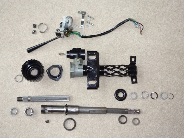
The plan worked. The other leaks were due to using aluminium crush washers on the carburettor banjo bolts rather than fibre washers. I suspect this might be a result of the zinc plating not providing a sufficiently smooth surface on the joint fuel pipe and banjo bolts. Some of John’s replacement handcrafted washers worked a treat.

Once the fuel issues were resolved, we needed to make sure oil had been circulated around the engine and sufficient oil pressure had been achieved. The battery was connected to allow the engine to be turned over on the starter motor to operate the oil pump. However the plugs and coil pack leads were removed to stop the engine starting.

There was no reading on the oil pressure gauge so we started to suspect the oil sender might be a fault. It was removed from the engine and the Mityvac vacuum/pressure pump (normally used for bleeding the brakes) jury rigged to check whether it was working correctly. It was and was measuring accurately, although with a fair amount of lag.

An oil pressure of about 18-20 lbf was finally achieved after running the starter motor in spurts for a while. A few from the E-Type forum confirmed that this should be sufficient to start the engine. The carburettors were adjusted to their default starting position: the damper oil levels checked, the slow running screw fully screwed down and then backed off two full turns and the mixture adjusting screws unscrewed to set the jet flush with the bridge before turning them each down by 2 1/2 turns.

So, for the first time in 18 years, the key was turned to start the engine …. it started on the first turn of the key!!


The only remaining problem is some airlocks in the coolant system which caused the coolant to be expelled from the expansion tank once the engine was stopped. Although I’ve found this is not uncommon.

 Posted by at 10:46 pm
May 232014
 

There was slight play in the upper steering which was found to be caused by a broken wave washer in the lower bearing components. Otherwise it appeared to be a simple matter of giving the painted parts a fresh coat of paint before rebuilding.

The ignition switch introduced for the S2 cars incorporated a steering column lock and is secured to the steering column housing with a security bolt. The hexagonal part of the bolt is designed to shear at a certain torque. Therefore, once in place, the only way of removing the switch/lock would be to drill out the remaining rounded head.

Steering column components Steering lock security bolt Ignition switch secured

First the outer column shaft needs to be secured into the column housing. The shaft is fed through the upper roller bearing into the housing and then locked into position by the lower bearing. The lower bearing and seat fit under a larger retaining cap and then a series of washers is fitted before the final circlip.

Outer column shaft Upper roller bearing Lower roller bearing

One of the washers under the circlip is a wave washer which provides a spring pressure once compressed. This preload removes the free play of the column shaft within the column housing.

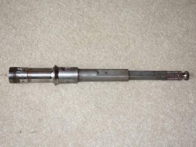
The inner and outer shafts engage on splines so the torque applied at the steering wheel is transferred from the inner shaft to outer shaft and finally on to the steering rack. However the inner shaft can slide longitudinally into the outer shaft to provide a level of adjustability in the steering wheel position. The rightmost picture below shows the inner and outer column shafts at both ends of their adjustability.

Fitting splined bearing race Retaining cap over bearing race Adjustability of column shafts

The stop button screwed into the outer shaft protrudes into a slot machined into the inner shaft, thus limiting its length of travel. A locking nut in the shape of a large black cup (not shown) is attached to the split collet by a circlip. When the cup is rotated clockwise it screws further onto the thread at the end of the outer shaft, compressing the collet and locking the inner and outer shaft together. Similarly rotating it anti-clockwise allows the collet to expand sufficiently, to unlock the shafts and enable the steering wheel to be adjusted.

The photo also shows the two nylon pins that enable the steering column to collapse. If the steering wheel is hit with sufficient force, such as in the event of an accident, the pins shear allowing the lower section of the outer shaft to slide into the upper section. At the same time the lattice structure of the column housing will also compress.

Finally to the trickiest part of the rebuild – the fitting of the indicator stalk mechanism. One which caused quite a bit of head scratching! Although in my defence, this was because one of the critical parts was missing. A previous owner had obviously taken the indicator off at some stage and bodged the refitting.

The missing item was the retaining clip (19). The correct fitting is the two screws pass through both the clip and a packing piece (16) and into the threaded holes in the indicator body. The combination of these two parts ensures that the rotational parts of the indicator are concentric with the column shaft.

The previous owner, Cap’n Bodger, had used the packing piece as the retaining clip as they are fairly similar in shape. However without a packing piece in the correct position, the indicator housing had been pulled too close to the steering shaft.

Over time this had worn down the white nylon ring operating the indicator mechanism. Unfortunately you can’t buy the nylon ring on its own and so the only solution was to purchase an entire replacement indicator stalk unit. However this still wouldn’t resolve the problem of the missing clip, which is no longer available from all the usual suppliers.

Even Google and eBay searches hadn’t found anything so the only option would be to fabricate one based on the packing piece. The completion of the steering column was put on hold for a month or so while I pondered what to do. When it was picked up again, I made one final eBay search, just in case …. a USA auction for a clip had finished two weeks ago although without any bidders.

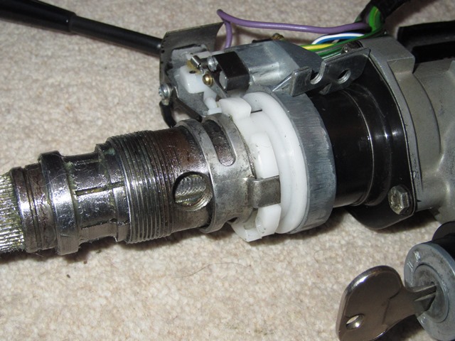
A speculative message was sent on the off chance they still had the clip. Shortly after came the reply that they did and a deal was done within an hour of contacting them. Result!

Back to the rebuild. The indicator stalk unit (13) followed by the indicator drive clip (9) are passed over the inner column shaft. The indicator packing piece (16) can then be placed in position but the corresponding clip (19) isn’t fitted at this stage as it will be necessary to move the indicator stalk unit and drive clip around to fit other parts. However once these parts are fitted it would be very difficult (if not impossible) to insert the packing piece. I fitted the split collet at this stage although this can wait until the cup-shaped lock washer needs to be fitted.

The packing piece has a small round protrusion which is aligned to fit into the corresponding hole in the indicator unit mounting bracket. This ensures the indicator stalk is at the correct angle once everything is mounted to the bulkhead. (Note: my mounting bracket had two holes and therefore possible indicator angles, I’ll adjust later to the preferred position)

Protrusion on packing piece Hole in mounting bracket Exposing stop button hole

The indicator stalk unit and the drive clip need to be pushed towards the steering column housing to fully expose the hole for the Stop Button so it can be inserted. The raised section of the stop button should end up near to being perpendicular to the column shaft.

The drive clip must then be push away from the steering column until it rests against the raised section of the stop button. This will expose the screw holes for the clamping bolts which secure the drive clip. Once clamped, this will obviously also lock the stop button in position.

Drive clip locks stop button Drive clip bolts & washers Finally the clip is fitted

The clip to lock the indicator stalk unit and packing piece tightly into position can now be attached.

The tab on the drive clip needs to engage with one of the slots in the white nylon indicator ring. Therefore when the column shaft is turned the nylon indicator ring turns at the same time.

A tooth on the rotating nylon ring will then engage with the cancelling arms to automatically cancel the indicator when the wheel is turned.

When connecting up the whole steering column on its various splines, the wheels will need to be in the dead ahead position and the indicator cancelling tooth mid-way between the cancelling arms.

The final components to go on are the split collet (although I had added this much earlier) followed by the large black cup shaped locking nut, which needs to be fully screwed onto the outer column shaft to reveal the circlip groove inside.

Fitting the circlip locks the two together and completes the upper steering column rebuild.

Later the steering wheel & boss will to be attached to the inner shaft. Once the split cone has been located in its grove, the splined steering wheel boss slides onto the inner column shaft until it meets the split cone and the central nut locks everything in place.

Steering Rack Fail Safe

Although the steering rack had been fitted for a while, I hadn’t added the steering rack fail safe bolts. Now the upper steering column had been completed it was time for a complete check of the steering system and fathom out the fail safe set up.

Note: this is only my understanding/interpretation of the fail safe as I see it, based on common sense rather than any qualified knowledge.

Rubber steering rack mounts are used to absorb some of the impact that would otherwise be transmitted directly through to the steering wheel if solid mounts were used. Therefore the ability to steer is totally reliant on in the integrity of the rubber and its bonding to the metal mounting plates.

The purpose of the fail safe set-up is therefore twofold; to maintain a level of steering input if the rubber/bond failed but, in doing so, avoid introducing any harshness to the steering feel that the rubber mounts were designed to remove.

Essentially the fail safe needs to allow the rack to move unhindered on its rubber mounts but to ‘catch’ it and limit its travels if the rubber fails.

Large retaining washers are fitted under the heads of the fail safe bolts. The bolts then pass through holes in the steering rack before being secured to the picture frame.

However retaining washers do not exert a clamping force on the rack and the holes in the steering rack are almost twice the diameter of the bolts. Therefore the rack is free to move on the rubber mounts.
Jaguar used different components for the driver and passenger sides but both are designed to achieve the same result; to stop the fail safe bolt & washer exerting a force on the rack.

Passenger Side Fail Safe – with lock nuts Driver Side Fail Safe – with spacer tubes

On the driver side, spacer tubes are fitted over the bolts. The length of the spacer ensures retaining washers are just proud of the steering rack. The spacer diameter is marginally smaller than the holes in the rack so rack movement is still not restricted.

On the passenger side, lock nuts are fitted to the bolts (or more correctly setscrews) instead of the spacer tubes. The lock nut and Nyloc nut secure the bolts to the picture frame so that the washers under the bolt heads are just in contact with the rack. Again, as it is only lightly in contact, it does not restrict the free movement of the rack.

If either rubber fails, the rack will only be able to move a small distance until the fail safe bolts or spacer tubes come into contact with the edge of the holes in the steering rack.

The question of why Jaguar used different components on each side of the car has been asked many times on the E-Type forum but there’s never been a definitive answer.

My guess, and it is a guess, is that the use of spacer tubes is a compromise between allowing the rack to move freely on the rubber mount and the need to provide sufficient steering input in the event of a failure by limiting its free travel.

The manual specifically states the spacers are to be fitted on the driver side of the car, so regardless of whether the car is LH or RH drive, the spacers will always be at the pinion end of the steering rack.

I suspect, if the rubber has failed, limiting the range of free travel is more critical at the pinion end where the steering column attaches. The spacers would reduce this range considerably. The trade off, in normal use, would be that the spacers are more likely to impact the edges of the steering rack holes on heavier impacts and therefore transmit more unwanted harshness to the steering wheel.

May 202014
 

The fitting of the windscreen was one of those tasks that I thought would be best left to a professional. One of the forum members had given a good feedback when their screen was installed by Howard of Merlin Motorscreens, based in Surrey.

Unfortunately I couldn’t arrange economic transportation of the rolling chassis to their workshop so it would have to be done in situ. As each car is different, I was warned that the installation may need to span over two days and that he may need to use his own supply of the rubber seals, depending on the quality of the SNG seals.

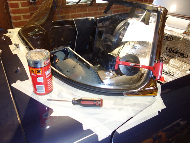
My only contribution to the whole process was to periodically returning to monitor progress and take a few photos of the various stages. On the positive side the SNG seals were useable. The whole area was protected with a generous covering of masking tape, the seals quickly trimmed to length and fitted to the windscreen flange using a bonding sealant.

In no time at all, the rubber seal had been lubricated with a soapy detergent allowing the screen to be eased into position from one side. A screwdriver was then used to get the final edge of the screen correctly seated into the seal. The next task was to tape the packing rubber strip to the top edge of the screen which sits between the screen and the top chrome finisher.

Windscreen slotted into rubber seal Taping the rubber strip Top chrome tapped into position

Re-chroming the top finisher can lead to distortion problems due to the heat created by the polishing process. Luckily my now banana shaped chrome finisher wasn’t too bad and he managed to tap it home with a rubber mallet.

At this stage you get the impression that the job is almost complete, but there was a lot more fiddly bits to do. There was much trial fitting of the A-post caps and chrome finisher to determine if and where additional packing rubber was required. The cavity under the rubber seal can be generous in places so additional rubber is pushed into these areas to avoid the screen dropping away from A-post caps later on.

Trial fitting A-post chrome Clamping the bonded chrome Completed A-post chrome

A beading strip could now be inserted into the rubber seal. Its purpose is to push the external side of the seal hard against the windscreen and mounting flange, locking the screen in position.

The chrome finisher, running along the base of the screen to conceal the beading, slides into slots moulded in the screen seal. Although contact adhesive is also needed to keep it in place in the long term.

The A-post chromes are also bonded into place although they are also fixed by screws along their rear edge and slotted under the A-post cap at the top. The interior trim also slots under the cap and therefore needs to be fitted at the same time. The bottom of the interior trims are secured by the same clips used to fix the door cards.

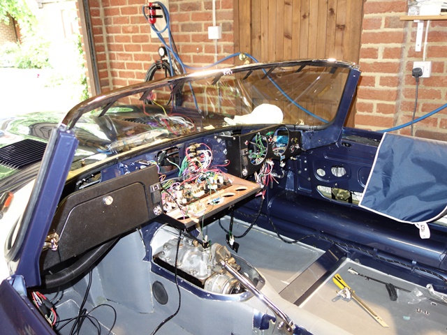
This leads to the logistics conundrum of what should be fitted first …. the final adjusting of the wiper linkages needs the windscreen in but the dash top off, to provide access the linkages. Putting the windscreen in, included the fitting of the A-post trims. However with the A-post trims in situ, it’s then not possible to fit the dash top!!

All that remained was to trim back the top rubber strip inside and out and remove any excess adhesive with white spirits. From start to finish it took just over 5 hours. If anyone in the South East is looking for their screen to be fitted, I would thoroughly recommend contacting Merlin Motorscreens.

Completed screen Interior A-post trim
May 132014
 

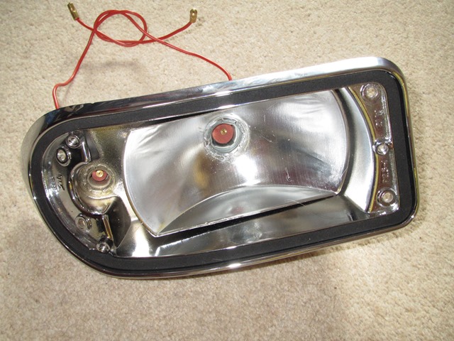
Fortunately it was possible to re-chrome the sidelight/indicators. However to do so ACF Howell had to remove the bulb holders and reflectors, neither of which faired out too well during the removal process.

The other problem was that one of the lens screws had sheared and I’d forgotten to remove the remaining section prior to sending everything to be re-chromed. So not only was it corroded in place but it was now sealed with a layer each of copper, nickel and chrome.

It was carefully drilled to break the plated layers and soaked in penetrating oil for weeks before attempting to remove it using a left handed drill bit. It wouldn’t budge so there was no alternative except to drill it out and re-tap.

Fine in theory but the lens screws are an odd size (approx. 0.130″ diameter and 32tpi). None of the local machine shops had a suitable tap and various internet searched failed to find one too. The closest tap was 6-32 at 0.136″ diameter which will now require a different size screw.

The next challenge was to find some new bulb holders which also proved to be very elusive. I finally managed to find some at the Stoneleigh spares day on a stall offering headlight re-silvering for very old classics.

The side lights require a bulb holder to fit a 5/8″ diameter hole while the indicator is for larger a 7/8″ hole. Once in place, the bulb holder edge is peened over to secure it in position.

The metal body of the light unit acts as the earth connection for the bulbs. A good earth would probably be achieved just by the four mounting screws, as the whole of the lower bonnet panel is earthed directly from the bonnet plug. However a brass bullet connector ring is also fitted to the indicator bulb holder and wired to the earth running in the loom.

Components for front lights Holder pressed in tightly Earth bullet connector

The indicator bulb holder is much harder to fit than the side light as the holder edge needs to be peened over tightly so the earth connector at the rear and the reflector inside aren’t wobbly. I rigged up a method of clamping the rear which took care of the earth connector. The reflector could then be held hard against the unit while a metal rod was tapped to peen over the edge of the holder. An additional pair of hands would have been very useful!

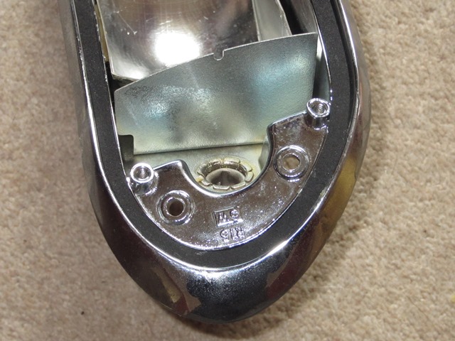
The disadvantage of someone else dismantling the units is not being able to recall what was removed. As a result, I’d overlooked the re-fitting of the internal shield. Fortunately it’s simply secured by two 2.4mm rivets and once in place, creates separate indicator and side lamp compartments.

Sprung bulb seats fitted Almost forgot the internal shield Shield riveted in place

I thought the rebuilding of the units would be fairly simple rather than the palaver it turned out to be to get replacement parts. It took three attempts to get the lens seating foam from SNG Barratt. Each time they were ordered I received the gasket for the side reflectors only found on US cars. Eventually we found out that my copy of their catalogue had a typo!

Fortunately the rubber boots fitted over the rear of the holders were in good condition as they’re not available any more. I also had to remake all the sprung bulb seat connectors as the wires were way too short.

Still that would be the least of my worries …. all the chrome units had been sent to Hutsons specifically so they could be trial fitted and the body work adjusted prior to painting. Both indicators were miles out and clearly hadn’t be fitted before the bodyshell was painted and the lights sent on to be re-chromed. Really not impressed.

It appears that the holes for the indicator units in new bonnet panels are approximate and need to be fettled quite extensively. I therefore had no alternative – I’d have to take a grinder to my painted bonnet to open out and reshape the hole. The accuracy of the bonnet panel is also amiss as I’m certain the indicator inserts haven’t been welded into the bonnet squarely.

The other odd thing is that only two of the four mounting points have nuts welded to the bonnet panel. Once the headlights are installed there won’t be access to the rear of the units. So I’ve had to fit some spire nuts in these holes.

The mounting holes in the indicator units also had to be enlarged to try to overcome the alignment problem. Even so, I’ve not been able to mount the units a horizontal as I would like. It’s something that will bug me now!

Complete unit ready for fitting Much fettling was needed to fit One down, one to go!
May 082014
 

The breakdown of the re-chroming quote received from ACF Howell simply had ‘RIP’ written in place of a cost for the rear light clusters …. and I had thought they looked in better shape than the front lights, which they were able to re-chrome! I was therefore slightly weary of picking up some second hand ones at the Stoneleigh spares day, just in case they too were later found to be beyond help.

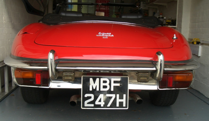
The general view is that the aesthetics of the S2 suffered with the tightening of US health and safety regulations, by the introduction of the rear wrap-around bumper and rather slab rear-end look. They have a lot to answer for!!

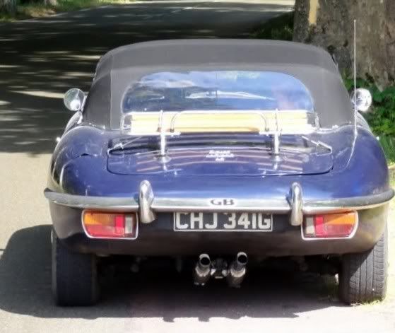
Peter Crespin, an author on Jaguars, had ‘tidied’ up the rear of an S2 based around using the rear light clusters from a Lotus Elan 2+2. These have a reverse light incorporated into the unit thus removing the need for the separate reverse lights either side of the square number plate.

Rear of Standard S2 Rear using Elan rear lights
Images courtesy of E-Type forum

The number plate mount and aluminium number plate finisher are also dropped enabling the more traditional oblong number plate to be attached directly to the body. This in turn enables straight exhaust resonators to be used rather than the splayed ones introduced with the S2.

While I much prefer this uncluttered look, I still wanted to be able to revert to standard relatively easily/cheaply. The main expense is the rear light clusters so the decision was whether to buy the correct ones or the Elan 2+2 units. The problem would be that having separate reverse lights might obscure the ends of the number plate.

A quick call to Framptons confirmed that they would be able to produce an oblong number plate which would fit inside the original reverse lights (just!), because my registration number only had two digits and one of these was a ‘1’.

Decision made. I would stick with the correct light units and the reverse lights but would swap to an oblong number plate and straight exhaust resonators.

One of the rear housings for the light units had been pushed in and badly twisted. Presumably when it sustained the rear bumper damage. Fortunately I managed to find a pair of second hand ones although their hand-painted finish looked as though the previous owner had had a fight with the paint brush …. and lost!! Nothing some shot blasting couldn’t cure.

The replacement housings may well have been from another Jaguar model because they didn’t have the retaining nut on the rear face and new ones had to be welded in place. The paint had been masking some quite bad pitting, so the housings were left to soak in phosphoric acid for a while to convert any remaining traces of rust before being filled and painted with Epoxy Mastic 121, along with the final few unpainted parts.

I also decided to give the inside of the housings and the back of the light clusters a number of coats of Dinitrol hard wax in an attempt to delay the onset of the same corrosion problems in future. Several thick coats of Dinitrol were applied – initially it looks a mess but dries overnight to a thinner, more uniform finish.

The parts diagram indicates that there should also be a foam gasket (item 5) sealing the aperture where the lamp cables exit the rear housing. Despite numerous searches, I couldn’t find anyone who supplied them so I knocked up some gaskets using some Dynaliner. The foam is closed cell so shouldn’t absorb water which would making things worse rather than better.

First the light housing must be attached to the body. The inboard side with two 3/16″ setscrews, one securing the light’s earth connection, and the outboard side with two 3/16″ self tappers into a square nylon span-in nuts.

However I found that once the housings had been fitted, it wasn’t possible to fit the bolts securing the rear bumpers. Therefore these bolts need to be screwed in place beforehand.

The bumper brackets slide onto these bolt so it’s not necessary to fit the rear bumper first. Although access to the bolts starts to become limits once the light units have been mounted to the housings.

I’ve found Bresco very useful for supplying many of the odd trim fittings and they supply a pack of the Nylon snap-in nut for 17/64″ square hole (code 80200P), which is sufficient for the rear lights, the reverse lights, the padded door brackets and the brackets for the internal door lever operating the door locks.

Oddly the inner two bolt holes of the reproduction light clusters were tapped. This didn’t make sense to me as it would stop the bolts providing a clamping force on the clusters against the housing. Once the screw had engaged with the thread in both the light cluster and housing, they would move in unison along the screw thread and would not be drawn together.

In the end I gave up and drilled the bolt holes to remove the screw thread to obtain a good seal on the rubber gasket between the two.

Finally the reverse lights and number plate light were screwed in place to complete the rear lighting.

May 082014
 

The pipes hadn’t fitted first time (probably due to an oversight on their part) but you can’t fault PD Gough’s after-sales service. The problematic tail pipes were returned within a couple of days.
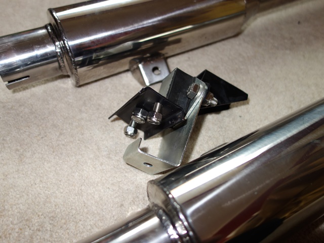
They had replaced the section of the tail pipe, which needs to slide over the silencer exits pipes, with a larger diameter pipe. These now fitted easily and snugly onto the silencer pipes.

One of the other issues was the geometry rearward of the silencers. The problem was the mounting brackets on the resonators were approx. 4-5 inches below the rear exhaust hanger bracket.

The returned pipes had reduce this to about 3″ so significantly less force was now required to raise the resonators to be attached to the hanger.

I’m still not 100% happy with the fitting as the rubber mounts are still subject to the fitting loading but it will do for now. When just the tail pipes had been refitted, they had a clear downward slope when they should be running horizontally under the IRS.

I think the remaining alignment problem is either due to the angle of the pipes exiting the silencers or the initial upward bend of the tail pipes. The latter will be easier to make so I’ll do this once the engine is up and running.

Apr 292014
 

Following standard practice, most of the external trim was trial fitted as part of the preparation of the bodyshell. This enabled the bumpers and/or bodywork to be fettled to ensure a perfect, even gap to the bodywork. Once completed, the bodyshell was passed on to the paint shop and the chrome parts sent off for re-chroming.

The exception was the rear bumpers which sadly had to be replaced. The car had obviously had a minor rear-end shunt that had resulted in a crease in the middle bumper section and the outer sections distorted beyond repair. Hutsons had trial fitted the new bumper sections, which they’d sourced from SNG Barratt.

One of the reported problems with the reproduction bumpers is that the chrome plating is generally thinner and not of the same quality as the originals. Even so, when the painted bodyshell and rear bumper were delivered, I wasn’t expecting to find the inside faces to be showing signs of rust!

I wasn’t too impressed as this really should have been spotted when they were being trial fitted and rejected. The dilemma now was that these fitted the painted bodyshell perfectly which may not be the case if I got Hutsons to replace them.

The intention had always been to paint the inside surfaces to provide better protection from the elements. So I decided to keep the new, rusty rear bumpers.

Meanwhile the remaining chrome trim had been dropped off to ACF Howell, who had been recommended. At the time, I felt reassured seeing many of the recognised Jaguar specialists listed on their white board of work in progress.

When they were returned, they’d already given the insides of the front bumpers and overriders a light coat of silver paint. However, on closer inspection, the paint was lifting in places on the overriders. Rather worryingly the cause was found to be more rust! So everything would be given a good coating of the silver Epoxy-Mastic 121 that I’d used on the front suspension.

Once all the chrome surfaces had been masked, the rusty areas of the ‘new’ bumper were bead blasted and the insides given three generous coats of epoxy-mastic followed by a couple of coats of Dinitrol 4010 hard wax. Hopefully this should be sufficient overkill to keep corrosion at bay for a while!

Apr 292014
 

The trial fitting of the exhaust system had highlighted a couple of alignment issues. The geometry of the pipes to the rear of the silencers was amiss somewhere. The result was that a considerable amount of force was required to push the resonators up sufficiently so they could be attached to the rear mounting.

This in turn raised the rear of the silencer on their mounts so one of the exit pipes was in contact with the floor strengthening panel. This was made worse because the silencers were not welded centrally on their mounting straps.

Also all the load would have to be borne by the small flexible rubber mount, which is merely to stabilise the rear of the exhaust system and not designed to take much load. I don’t think it would have lasted 5 minutes out on the road!

At the time, the down pipes from the manifold hadn’t been fitted. So the makers, PD Gough, suggested everything would be brought into alignment once they were fitted. I was far from convinced. So it wasn’t too much of a surprise that the exhaust system didn’t fit once the engine was installed and the down pipes were in place.

The issue was now getting the entire system back to them to sort it out. I thought it would be easier in the long run to make the 300 mile round trip to be able to discuss the issues in person. To their credit, they were very helpful and offered to remake the tail pipes that pass under the rear suspension and remount the silencers to their mounting straps.

They also showed me around their workshops and the many 1,000s of original exhausts they use for templates. I suspect my fitting problems were simply because of the compounded effect of a couple of the bends being slightly out.
Fast forward several months; the underfloor heatshields had been fitted, the damp winter weather had passed enabling the touching up of the chassis rails where the chassis had been mounted to the painting rotisserie and the final adjustments made to the handbrake.

It was finally time to fit the exhaust in preparation for starting the engine.

The downpipes and silencer sections fitted without any major issues. Although I’m slightly concerned about the clearance between the rear down pipe and the torsion bar. Next to be fitted was the re-made tail pipes …. they wouldn’t slide over the exit pipes from the silencer section. Aaaargh!

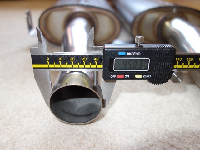
The silencers were removed to see what was going on. The silencer exit pipes had an outer diameter of 45mm yet the tail pipes had been made from 44.5mm piping with a wall thickness of 1.2mm. So the internal diameter was almost 3mm too small – they’d forgotten to swage the pipes to accept the 45mm pipes.

These are meant to slide into …. …. these. I don’t think so!!

I can’t believe they hadn’t bench fitted it when it was re-made. Perhaps they overlooked this step in the rush to turn it around on the same day. Rather frustrated, I took the offending pipes to a local exhaust fabricator to see if they could open out the pipes rather than return them again.

Unfortunately their view was that the swaging could easily cause the pipe to crack due to the combination of a relative thin wall thickness of 1.2mm and the fact that the expansion slots had been cut at the ends of the pipe could.

Reluctantly the tail pipes have been returned to PD Gough to fix. So the starting of the engine must wait for their return.