Chris

Apr 132015
 

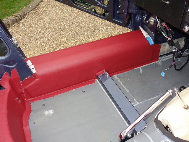
Trimming wasn’t something I was looking forward to! My kit had been supplied by Suffolk & Turley. The only thing that appearred to be missing from the kits from all the various suppliers is any form of guidance, let alone detailed installation instructions!

It was very much a case of trial and error, never having trimmed a car before! So what follows is the approach that worked for me (and in some cases not!!).


A simple jigsaw puzzle!!

The kit consists of all the jute underlay, vinyl, Ambla, Hardura, vinyl covered panels and carpets. So one would assume it’s all fairly obvious how it should be installed. It’s the subtleties that are not explained! The trimming of the seats and central console were beyond my capability, so these had been supplied ready trimmed.

The initial focus was to get the car through an MOT and then do the interior trimming. However the decision to install boot-mounted inertia seat belts had put paid to that! They required most of the trim behind the seats to be fitted first.

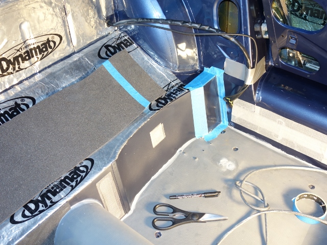
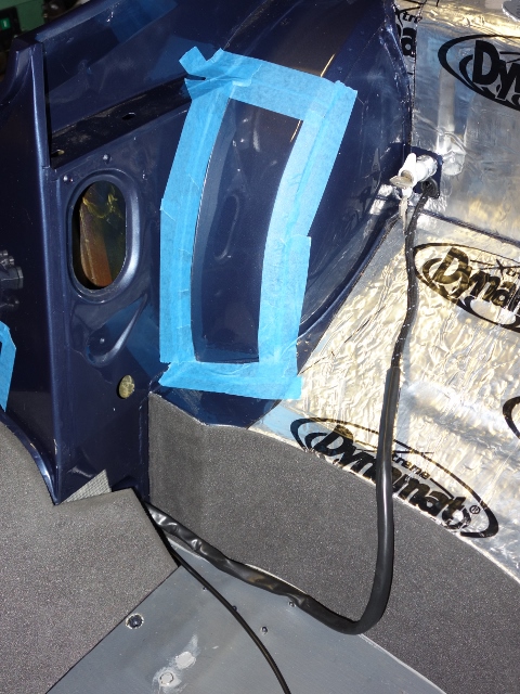
The kit contained some 5mm open-cell foam underlay for the sills and rear wheel arches. The problem with this foam is that it isn’t very robust, losing its spring quite easily and disintegrating over time. I therefore decided to replace this with a denser closed-cell polyethylene foam, sold under the brand name Plastazote and available in a variety of densities and thicknesses.

As it’s denser, it won’t compress as much as the open-cell foam and so the edges would be more pronounced through the vinyl covering. I decided to purchase both 3mm and 5mm medium density sheets (Plastazote LD45) with a view to playing around chamfering the edges to get the finish I wanted. The decision was to use the thicker 5mm foam for the sills and wheel arches as it gives a softer, more luxurious feel. The lower rear bulkhead is normally just covered with Ambla (vinyl with an expandable knitted backing) but this would be covered with the 3mm foam first.

The trim covers recesses in the rear bulkhead and the wiring loom channels in the sills, which can become visible over time if the material pressed in. In an attempt to stop this, these areas were covered with reinforced cross weave tape. I also ran guide strings within the loom channel in case I need to run power to the rear of the car in future, eg for powering security/tracker devices.

Guide strings added – just in case! Then loom channels were taped over

Lower rear bulkhead
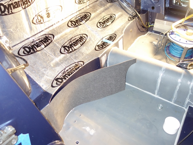
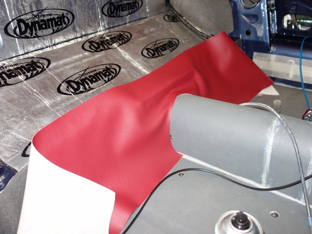
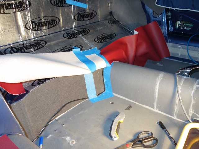
The 3mm foam was bonded to the rear bulkhead with a spray-on high temperature contact adhesive, purchased from Woolies Trim. It was more manageable to tackle it in two sections with the join above the transmission tunnel. Each section was then glued in three phases: the outer flat section, the concave area behind the seat and finally the small area around the transmission tunnel.

This approach allowed the non-glued section to be held against the bulkhead to make sure it was square across the full width before pressing the bonded area onto the bulkhead. The contact adhesive doesn’t allow a second attempt so it really does have to be right first time.

Each side was started at the sill end Next the concave section Foam in place … now the vinyl!!

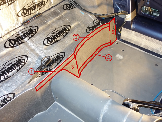
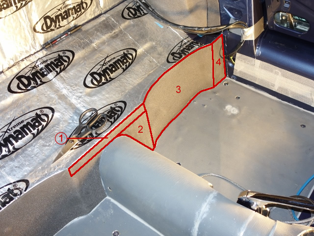
I’d read other restoration websites covering the interior trimming, where they explained the vinyl should only be bonded to the perimeter of the foam underlay. So I followed this approach for gluing the Ambla to the rear bulkhead. Again I decided to tackle it in smaller manageable areas – the order as shown in the left photo below.

Areas and order of gluing the Ambla So far so good … section 1 bonded!

It was all going well up to section 3. To avoid wrinkles, the Ambla needs to be ever so slightly stretched as it is bonded to the foam. However, when the lower area (4) of the concave section was glued to the foam, the un-bonded area between (3) and (4) pulled away from the foam, as the Ambla contracted.

I tried to pull the Ambla away from the foam as soon as I realised but this just resulted in the latter being ripped apart. Aaaargh! Both the Ambla and foam were ruined. It took many messy hours to remove the remains of the foam, back to the painted bulkhead so I could start all over again.

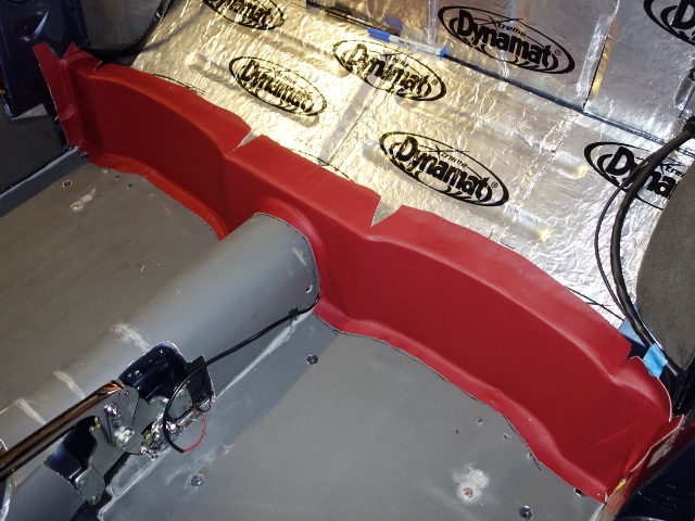
The revised plan was to bond the whole contact area between the foam and Ambla. This time the process followed the sequence of bonding the foam, although in reverse – working from the transmission tunnel out to the sill, as the whole area needs to be covered by a single piece of material.

Revised area and order of gluing Bonding area limited by matching masking
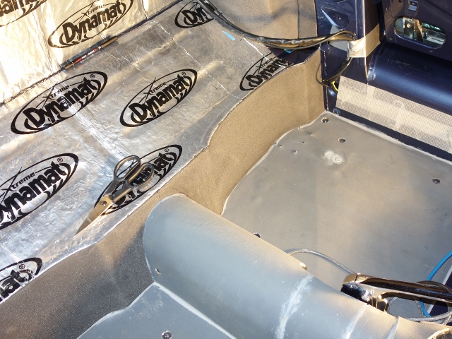
The second attempt worked well The lower bulkhead trimming completed!

The main difficulty with the rear bulkhead Ambla is it needs to cover the body looms to the rear lights, fuel pump and tank sender. The sills have a recess to hide the looms but they stop just before the end of the sills so there is no tidy solution.

Sometime later, I was trying to find the best method of hiding the wiring looms as they travel around the lower edges of the wheel arches before entering the boot space. I couldn’t disguise the looms under the Hardura trim covering the rear bulkhead and so dug out the remains of the original trim to see if I could get any clues.

The (non-vertical) areas should first be covered by a layer of jute before the Hardura goes down and the excess bulkhead Ambla bonded over the jute. The trim kit didn’t include jute for this area, and indeed some for the rear face of the boot, so it was easily missed.

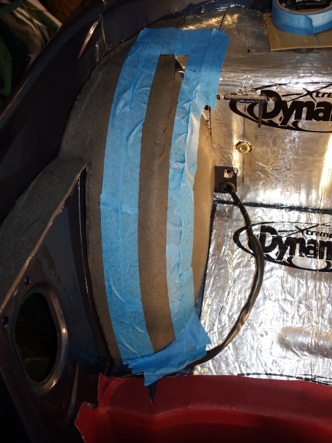
Although I had already fitted Dynamat sound insulation, it is much thinner than the original jute layer, and therefore not able to disguise the looms. The solution will be to fit some 1/4″ Dynaliner, with suitable channels left for the looms. The down side is that the excess Ambla will have to be lifted and re-bonded over the Dynaliner.

The Ambla was bonded over the looms Different bonding was needed against the Koolmat

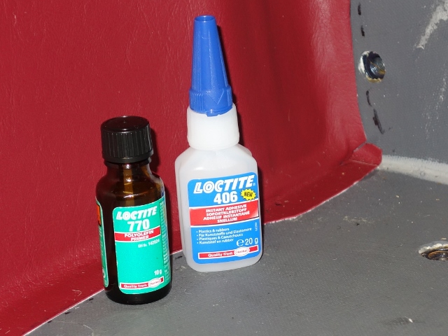
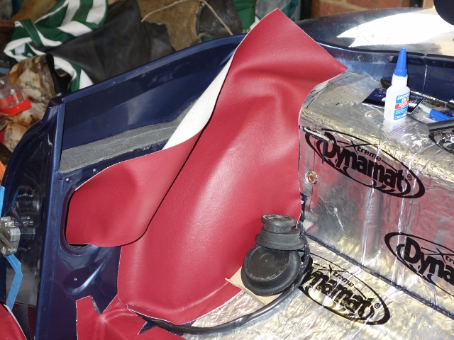
The other issue was trying to bond the vinyl and Ambla to the silicone Koolmat, used to insulate the cabin from heat soak from the engine bay. I’d previously tested various adhesives such as contact adhesive and silicone RTV adhesive. Since then I’d found that Loctite produce a silicone surface preparation fluid (Loctite 770) which enables the ‘superglue’ Cyanoacrylate family of adhesives to bond to it. The combination of Loctite 770 & Loctite 406 superglue provided a very good bond and was used to secure the overlapping vinyl and Ambla to the grey Koolmat.

Sills
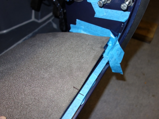
The 5mm foam and vinyl covering the sills were fitted, again in stages, working inwards from the outer edge. The foam was cut so there was a 1cm gap to where the sill meets the A & B-posts and also the floor. This was to provide a bare area of sill for the vinyl to securely bonded to.

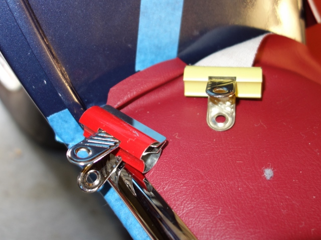
For the gap to the sill edge, the chrome finisher was offered up. A gap of approx. 13mm would avoid foam being trapped under the chrome trim as it’s a fairly tight fit at the best of times. I didn’t want foam underneath to make things worse. The vinyl wraps around the sill lip and should be held in place by a number of metal clips.

A gap was left between the foam & sill edge First stage of bonding the foam underlay

I had a trial fitting of the clips using some scrap vinyl to see if they would stretch the vinyl as they were pressed on. No matter what I tried, I couldn’t get the clips on. I mentioned this to Suffolk & Turley when I was up discussing the hood – they don’t bother with the clips! They just run a bead of silicone RTV adhesive in the chrome finisher, wedging it in place while it cures. A tip I will be using once the sill door rubber is in place.

The approach of applying adhesive to the whole foam/vinyl contact area worked well with the rear bulkhead and so would be repeated for both the sills and rear wheel arches.

The vinyl was started by just bonding the 13mm strip at the sill’s edge. The aim was to anchor the vinyl in place as it would require cutting to shape as it was applied. The spray adhesive doesn’t give any room for adjustment once the two surfaces have been pressed together. So I thought it best to use the brush on Alfabond AF178 for gluing the sill edge and then pressing on the chrome finisher to hold it all in place, while it set.

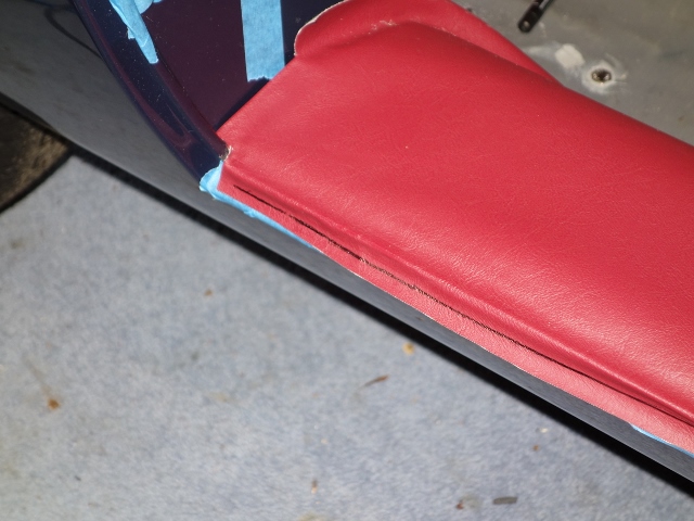
Marking out the excess vinyl Excess can cause door rubber problems Bonding underneath the sill edge

Adhesive wasn’t applied to the underside of the sill edge, which allowed the vinyl to be pulled out to cut off any excess before being bonded. Too much excess can lead to problems fitting the sill door rubbers later on.

The edge of the vinyl is visible for a few inches; forward from the door opening to the A-post; reward to the B-post and 2-3″ along the outer face of the B-post (before it is hidden by a vinyl covered panel). The vinyl was doubled over to keep these edges neat and tidy.

The visible edges were doubled over to keep them neat

As the vinyl doesn’t stretch like the Ambla, a number of cuts were needed as it turns down towards the sill. There were a number of scares along the way where I didn’t think it was as smooth as it could be. The on-the-fly remedies often made matters worse. Fortunately the foam regained its shape overnight!

Again, bonding was done in stages Trimming around floor strengthener Sill vinyl almost completed

Overall I was quite pleased with the results. If it were to repeated, I would probably only leave a 5mm gap between the foam and the A & B-posts.

Rear Wheel Arches
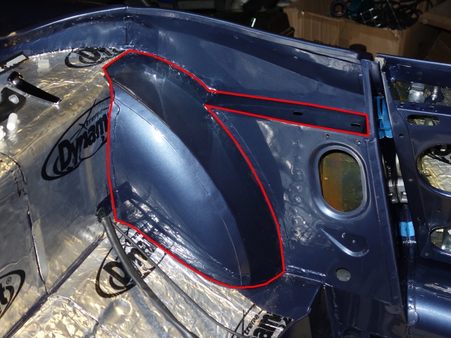
The trimming of the rear wheel arches appeared to be much trickier due to the double curvature …. and so it would prove to be!! The pre-cut material has a very odd shape as it covers the wheel arch and a flat section underneath the hood mounting brackets.

Area covered by the wheel arch Ambla …. hence the odd shape of the trim provided

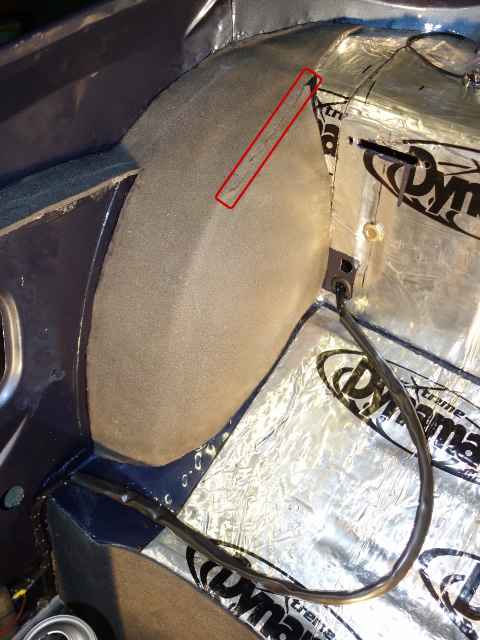
Numerous dry runs were done before deciding on how best to tackle it. Initially I started with bonding an outer section of the wheel arch, and the working down towards the lower rear corner. It soon became apparent that this wasn’t the way to go.

It left too much foam being pressed into an ever decreasing area, causing ruffling. Fortunately it was possible to cut out a section of excess foam and make a joint that would be invisible through the Ambla. This wouldn’t be an option when the Ambla is fitted.

Initial area bonded on 1st attempt Resulting in section cut out of foam

For the Ambla, it was decided that it would be best to glue a 2” strip down the shoulder of the wheel arch but stretching it as it went down. The reasoning was it would therefore reduce the excess material in the corner of the wheel arch.

Bonding this area first caused numerous problems!

Unfortunately this didn’t prove to be too successful and it was a real fight to get the lower edge glued without it puckering up along the join between the wheel arch and the bulkhead. Occasionally some Heath Robinson techniques were needed to weigh down the Ambla until the adhesive had dried. I shouldn’t have been surprised as it was not too dissimilar to the approach for the foam. A re-think was required for the other wheel arch!

Weighing down the edges to stop it lifting Bonding the lower edge worked better

The other tricky area was where it transitions between the curved wheel arch and the flat section. The Ambla just had to be stretched in the right direction to get a smooth finish.

For the second wheel arch, a 1.5” strip was glued along the lower edge. The foam could then be stretched up to the corner where it meets the top of the rear bulkhead. This ensures the Ambla is ripple free as it is being stretched over the curvature of the wheel arch. Initially this appeared to be a much better approach although it simply transferred the problems encountered later on to another area. The conclusion is that the wheel arches are just difficult to trim.


An Ambla covered wheel arch. Phew!

The trimming of the vinyl and Ambla was quite tricky and took over two weeks to complete, mainly due to putting off tackling the difficult areas and procrastinating too much! It would have been almost impossible to complete without the assistance of my trusty helper who patiently held the material up, while it was being smoothed into place and took the brunt of frustrations when things didn’t go as planned!

In hindsight, I wish I’d have bought shares in 3M with the amount of blue masking tape I ploughed through!!

Hardura and carpet fitting will be covered in Part 2 ….
Mar 252015
 

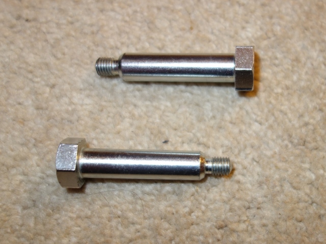
New hood pivot bolts

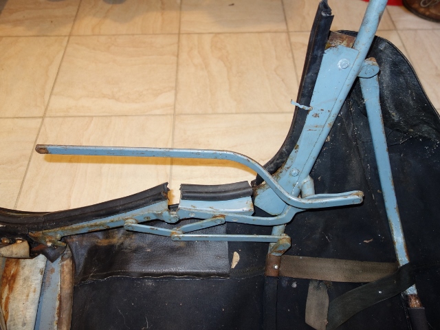
The removal of the hood many years ago had been problematic to say the least. The threaded section of the pivot bolts is a much smaller diameter than the unthreaded section, which the hood sticks pivot around. The bolts wouldn’t come free even after applying penetrating fluid and adding an extension piece onto the ratchet handle. The force being applied was more likely to shear the threaded section, so I stopped to have a re-think.

However the problem wasn’t that the threaded sections had seized within the bracket’s captive nuts as I had thought. Small holes are provided in hood sticks for oiling the pivot joints. Unfortunately it’s doubtful they had ever been troubled during routing maintenance!

The result – the whole pivot joint had rusted, fusing the bolt to the hole in the frame. The hood no longer pivoted on the bolts. The bolts and frame just rotated in unison in the mounting brackets, as the hood was raised and lowered. The only way I could then remove the hood was complete with mounting brackets.

I couldn’t believe how solidly they had rusted in place. In a foolish fit of pique, I ground away the heads of the bolts, which were looking decidedly rounded by this time. Cutting through the threaded sections to finally free the hood from the brackets. The whole hood was left, as is, until now so I still had to overcome the issue of removing the remains of the bolts.

The remaining sections of the bolts wouldn’t budge even after soaking in Plus Gas penetrating fluid for several weeks, applying heat, attempting to press them out in a vice and, in a Cleese-esque manner, giving them a good thrashing with a club hammer!

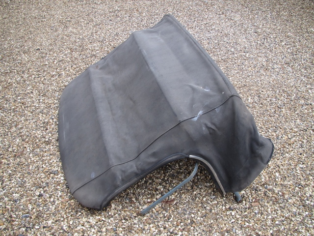
The hood needed a full overhaul Every hood fixture was heavily rusted First, removal of the old canvas

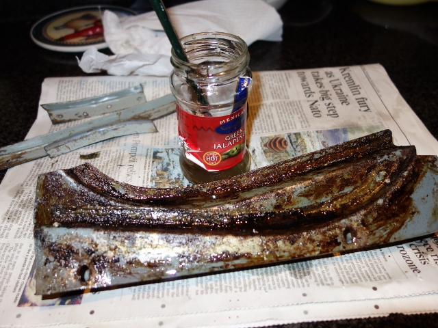
The plan is to have the hood professionally fitted by Suffolk & Turley. Even though they will happily undertake all the work, including the renovation of the frame, I wanted to do as much as possible myself. So I set about removing the canvas and dismantling the frame into its components on order to have them powder coated.

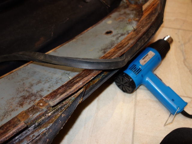
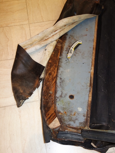
First, the canvas was detached from the rear of the frame – by removing the side chrome trims, which clamp the canvas rearward of the drop glass and unpicking the webbing attaching it to the frame sticks. Removing the hollow, square-sectioned rubber seal, which makes the seal against the top of the windscreen, reveals the canvas and vinyl edges in the channel underneath. The canvas and vinyl could then be pealed off the canopy, while applying heat to soften the adhesive.

Main head/cantrail brackets attached to frame Bonded edge of canvas/vinyl under screen seal Vinyl removed revealing wood canopy bows

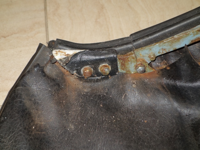
The detaching the cantrail and main head brackets also proved troublesome. The removal of the pivot bolt remains was soon joined by the need to remove half a dozen screw stubs. Some of the screws fixing the main head/cantrail brackets and hood clamps had sheared or had to be drilled out. Their slotted heads had become too damaged by attempts to unscrew them.

Latch covering trim under two canopy mounting bolts Softening old adhesive with white spirit

The pivot bolts were removed by drilling a pilot hole down the centre of the bolt. It was more important to keep the pilot hole square on to the bolt than ensure it was precisely centred on the bolt. Progressively larger drill bits were used to enlarge the hole until a line of rust could just be seen running down the length of the hole. A pointed drift was then used to collapse the perimeter of the bolt inwards allowing the bolt remains to be pushed out.

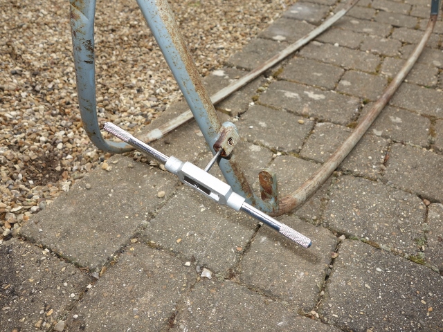
The same approach was followed for the screw remains in the hood sticks. Although this time it was essential that the drill bit was centred on the bolt so the thread wasn’t damaged. They were then re-tapped to reinstate the thread.

Initially the canopy didn’t look too bad but it had clearly been worked on before as the whole frame had been hand-painted a light blue rather than the original light grey. The forward wood bow had a small section missing and it had started to delaminate. The edge of leading edge had rusted away along the entire length of the canopy although it should just be a matter of welding in some new metal.

The leading edge has rusted away The wood bow was also delaminating Re-tapping the frame after drilling out screw stubs

A second opinion was needed so it was taken up to Suffolk & Turley in Nuneaton. Their evaluation was not good, enquiring whether I’d found in it a canal! In addition to the problems I’d spotted, they pointed out that the lip where the two outer skins meet had been cut away at one end. It should be proud of the wooden bow by approx. 2cm as it forms the upper part of the channel for the rubber seal. Also, the front 6 inches across the full width of the canopy was largely filler.

Their preference is to re-use original parts rather than replace. The replacement wood bows are available but the quality is not great and it takes some work to get them to fit. Even so, their verdict was it wouldn’t be cost effective to repair the metal canopy and the front wood bow was unlikely to survive its removal. Only the rear wood bow was worth saving, as these are no longer available.

It was a long way to travel to learn that the canopy was junk and I was now resigned to inevitable fleecing that was coming my way! Both for a new metal canopy and a wood bow, which I believe is north of £300 from SNG Barratt!

As luck would have it Martin Robey had one S2 canopy left in stock so it was secured on the spot. A week or so later it hadn’t turned up so I gave them a call. It was ‘virtually’ in stock … they just had to make it first! Two months later it finally arrived.

In the meantime I’d found a Czechoslovakian subsidiary of the German company Slavik, which made all the wooden components for earlier Jaguars, and at a very reasonable cost of £75 for the wood bow. They were making a trip to the UK a few weeks later and suggested sorting out the payment and shipping once over here. Needless to say, I didn’t hear from them so I presume they forgot to bring it and I got no response from follow up emails.

Trial fitting the rear bow to the new canopy Replacement canopy wood bow

Finally a piece of luck, a wood bow appeared on eBay. I’d lost so much time waiting for parts, I contacted the seller and agreed a private sale, rather than wait until the end of the auction. A trial fit of the bow with the new Robey canopy confirmed it will need a fair amount of fettling to get it to fit.

Now I had all the components, it was off to Nationwide Coatings”to have them powder coated in BS381C-694 ‘Dove Grey’. The advice from the E-Type forum was that this was the correct/nearest colour match. Typical …. the powder coating manufacturers no longer supply powder covering the old BS381C range!


Original paint allowed a colour match

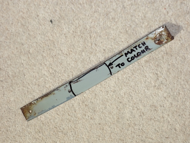
Traditional paints do not adhere to powder coating. However new paints have been produced specifically for this purpose. So they recommended powder coating the hood components to the nearest light grey colour available and then over-coating with a colour-matched paint. A couple of parts had hidden surfaces that missed being hand painted in blue so they will be used to get an exact match to the original colour. The powder coating should provide the durability while maintaining the correct colour.

My aim had been to get the car ready for a trip to the Monaco Grand Prix at the end of May. This is now looking to be a very long shot, having lost two months waiting to just trial fit the hood. Also, in a nod to practicality, I’d decided to fit inertia seat belts rather than static seat belts. These have been on order since the New Year and there’s still no confirmed delivery date. The fitting 3-point Seat belts became mandatory from 1968, so I won’t be able to get an MOT until they do.

Feb 262015
 

The brakes have been connected and plumbed in for quite a while now. The system only had to be filled with brake fluid and bled, so I had assumed the brakes were essentially complete and wouldn’t be noteworthy. I should have known by now that was almost certainly going to be wildly optimistic …

I had dithered on the type of fluid to use, glycol base or silicone, changing my mind almost on a daily basis before finally making the decision to stick with glycol based DOT4 fluid. The ‘this is absolutely my final decision’ was subsequently reversed to silicone following an interesting article on the subject sent to me by Chris Jackson, whose restoration is being covered in the E-type Magazine.
DOT5 Silicone Brake Fluid

The debate regarding DOT4 (Glycol) verses DOT5 (Silicone) seems to be quite polar in nature. A bit like Marmite – people are either for it or hate it and never the two shall meet! At the time I’d just been working through fixing leaks in the cooling system. Reports of leaks from weeping hoses and splitting repro reservoir bottles are all too common. The thought of brake fluid leaking onto the paint work and remaining undetected paid a significant part in opting for silicone.

However some have raised concerns that silicone fluid might cause rubber seals to swell. Possibly but the composition of the rubber seals has changed over time, with natural rubber no longer used. Modern rubber should now be compatible with all types of fluid.


Automec DOT5 Silicone Fluid

The manufacturer’s blurb suggests silicone fluid is a ‘fill and forget’ solution but I think this is a little wide of the mark as water will find its way into the system. As it doesn’t mix with the brake fluid, it would then pool and cause local corrosion so I’m still planning to replace the silicone fluid periodically, although less frequently than would be the case for DOT fluids.

Apart from the additional expense, the down side of silicone is that, when it is agitated, it has a tendency to absorb tiny air bubbles that are not visible to the eye. This can cause a spongy pedal as the bubbles compress under braking. The simple solution is to leave the fluid to settle overnight before bleeding the system, although that would be more problematic if it ever had to be refilled on a trip.

All the compression joints were checked and tightened. Now the front calipers were bolted to the uprights, sufficient torque could be applied to the bolts clamping the two caliper halves together. Correct torque settings are not published but a brake refurbishing company recommended to torque the 7/16″ diameter bolts to 70 lb-ft and the 3/8″ diameter bolts to 40 lb-ft. I’ll need to keep an eye out for any initial issues.

Remote rear bleed kit


Stevson & Fosseway kits

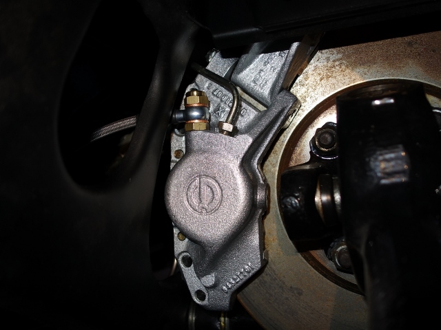
Another of Chris’ suggestions was to fit one of Fosseway Performance’s remote bleed kits. The standard bleed valves are hard to reach at the best of times, so moving them to a more accessible position on the IRS cage is quite a popular modification. In fact I’d already fitted a similar kit sourced from Stevson Motors prior to installing the IRS unit.

My kit was definitely more agricultural than engineered so I had been a little disappointed when it arrived. The mounting brackets were just pieces of brass sheet that looked as though they had been hand drilled and then bent in a vice.

Still their function is fairly basic and the aesthetics is not a great issue, being tucked up underneath the car, so I had fitted the Stevson kit. It was only later, when I was working underneath the car to re-fit the handbrake cable, did its design start to irk me. My patience was wearing thin after catching the sharp corner of the brass bracket for the umpteenth time.

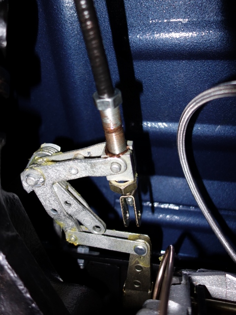
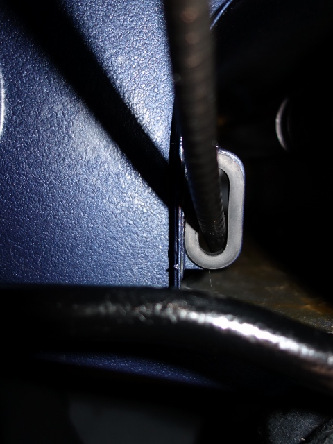
The revisiting of the handbrake was because I’d routed the cable incorrectly. It should pass through an eyelet on the inside of the transmission tunnel, with a rubber grommet protecting the cable. The cable was too stiff to re-route in situ by disconnecting the cable from the handbrake mechanism. So the entire cable had to be removed.

Re-routing couldn’t be achieved by just disconnecting at compensator linkage Correct routing of cable through grommet in transmission tunnel eyelet

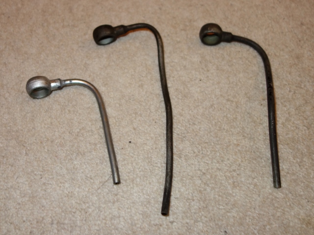
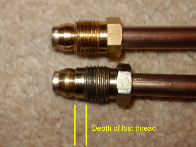
The final straw came when I found that the seat for one of the bleed valves had been machined too far. So the coned face at the end of the valve could never make contact with the seat, let alone form a seal. Longer valves are available … but not in the course thread used in the kit. There was no alternative – it had to be replaced.

I’m sure Stevsons would have rectified the problem but I now had the opportunity of fitting a better quality of kit. An order was placed and the Fosseway kit arrived the next day! The main difficulty was, with the IRS now in place, access was severely limited. The front pair of springs and dampers had to be removed to access the calipers.

Forward rear springs removed for access The Fosseway kit has better banjo attachments Fosseway kit uses sprung bleed valves

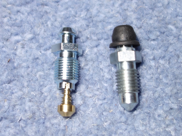
The Fosseway kit uses a banjo attachment at the calpiers which is a neater solution and much easier to fit, as it doesn’t require the flexible pipe to rotate when tightening it into the caliper. The other difference is the style of bleed valve used, sprung valves rather than standard solid valves. The sprung valves help with bleeding as the spring stops air entering the system between pumps of the brake pedal. In the end, replacing the remote bleed kit was easier than I had thought and only took an hour and a half.

Brake Bleeding Woes!
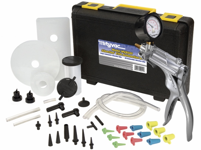
This was another task that proved far more troublesome than I had expected. Most methods of bleeding require the help of an assistant. The exception to this is vacuum pumps, such as the Mityvac, which can be operated single-handed. The vacuum is applied to the bleed valve to draw the fluid through the system so both the vacuum and bleed valve can be controlled from one location.


Mityvac vacuum bleeding tool

It was for this reason I purchased a Mityvac pump to replace my old Eezibleed tool. The Eezibleed pressurises the reservoir to push fluid through the system but still requires two people to operate. So doesn’t really offer anything over the traditional method of pumping the brake pedal.

The correct bleeding sequence according to the service manual is the near-side followed by the off-side, starting with the rears and finally moving to the front brakes. The reservoir bottles were filled, the RH reservoir feeding the front brakes and the LH reservoir the rears … let the bleeding begin!

After about 1/2 hour of trying with the Mityvac, absolutely nothing had come out of either of the rear valves. Time for plan B – the Eezibleed was rigged up to the reservoir. All this achieved was pressurising the bottle to what looked like bursting point and spraying fluid everywhere from around the cap. Thank goodness I’d gone for silicone fluid! Still nothing was coming out at the rear calipers.

Plan C! The traditional approach – the good old brake pedal and a patient helper! The resistance started to build after 20-30 pumps of the brake pedal. However this would dissipate after about 30 seconds. Frustratingly there was still no fluid coming from the rears. I suspect pumping the pedal was only pushing fluid into the front circuit and the resistance felt at the pedal was due to the air in the pipe being compressed. Once the pumping stopped the air pressure would force the fluid back into the reservoir.

Stumped, I decided to search the web to find out if there was a specific technique or trick that might help. At least I found out that I certainly wasn’t alone in having trouble bleeding the rear brakes, especially filling a dry system. One tip was to try bleeding the brakes with the engine running as the servo would be boosted by the vacuum. Still no joy!

Another suggestion was to first check the operation of the valve located in the output port of the servo cylinder. Once it had been confirmed fluid was coming out of the servo cylinder, simply loosen the rear bleed valves in turn, allowing the system to bleed naturally, under gravity. Note: the sprung valves need pressure to compress the spring to allow fluid out and so had to be removed for this method

The height of the reservoir above the remainder of the system provides a sufficient head of fluid to allow gravity to do the work for you. Whether the removal and inspection of the cylinder valve had fixed the restriction I’m not sure, but fluid was now coming out of both rear bleed valves.

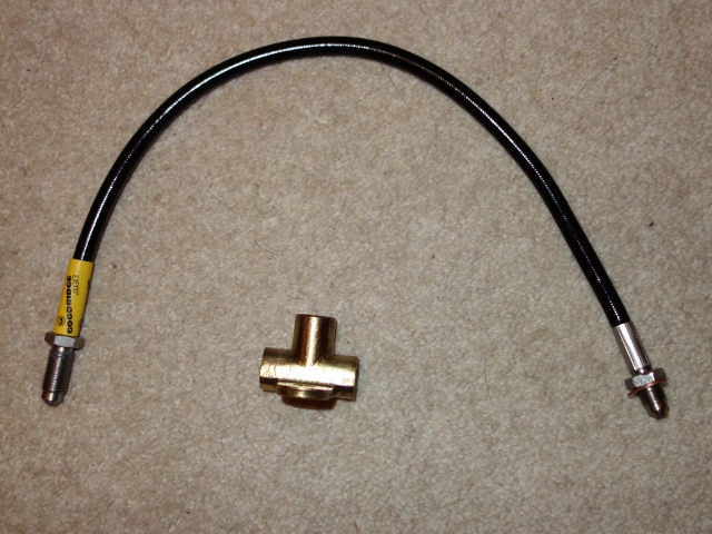
Success was short lived …. when the brake pedal was depressed, fluid leaked out of the three way union mounted on the IRS cage. The problem was found to be the new flexible Goodridge brake pipe. Although sold as a direct replacement for the E-Type, the rear attachment was too short. It was a similar problem to the remote bleed kit – the attachment could never make contact with the seat and therefore create a seal.

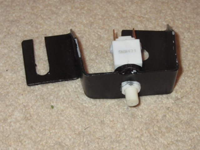
Short end of Goodridge brake hose was too short! The additional mechanical brake light switch

Several days and a new hose later, the system was finally bled. At the same time the last few braking tasks were completed: the brake pedal was much higher than the accelerator pedal and the mechanical brake light switch was fitted.

The height of the pedal is set by adjusting a ‘stop’ screw in the pedal housing, which was set to remove any free travel in the brake pedal. Unfortunately the clutch pedal is too high as well but this doesn’t have any adjustability. Other owners have had the same problem, caused by the push rod being 1/2″ too long on the replacement master cylinders. Another job to the list!

Feb 252015
 

The installation of the fuel tank had taken a number of fitting attempts and required the enlargement of one of the mounting holes. The toing and froing had inevitably resulted in a couple of light scratches inside the boot space. So I decided to remove the tank for a final time to paint the exposed metal in the mounting hole and touch up the scratches.

The tank was completely wrapped in sheets before extracting it to avoid further scratches. As it was being lifted clear the sheet snared on the corner of the flange for the boot boards, stopping the tank in its tracks and putting me off balance …. the tank came down on the rear wheel arch!

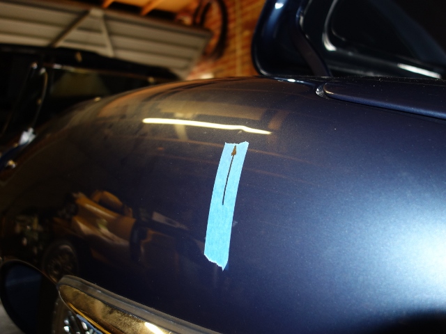
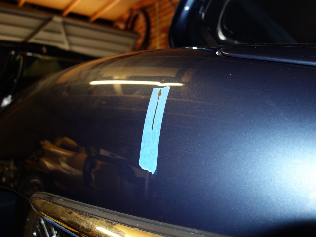
Even though it was the lightest of landings, the weight of the tank was sufficient to put a dent in the wheel arch. It was less than a 1cm long but, as its on a double curved surface, it stood out like a sore thumb. Absolutely gutted!

Even though it’s a small dent, your eye is drawn to it The irony of it all: it’s hard to photograph!

The only saving grace was the sheet had offered some protection and the paint wasn’t damaged. I’d seen companies offering a paintless dent removal service. It had to be worth a go so I contacted a guy operating under the name Dr Dent.

His toolkit appeared to consist of a vast number of levers in all shapes and sizes which are used to press out dents from behind. A couple of minutes later (most of which was spent chatting!) and he was out with the polisher – job done! Even right up close, I can’t find where it was dented. Needless to say I would thoroughly recommend him if you’re equally careless!

Good as new! Chuffed!
Feb 102015
 

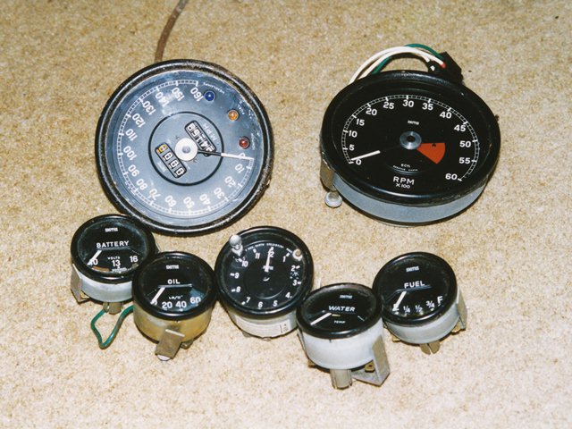
The green illumination of the dash gauges is achieved by plastic green filters within the gauges. However almost all of these filters had deteriorated due to their proximity to the incandescent bulbs. Some had actually melted due to the heat produced. I had therefore decided to ‘upgrade’ to LEDs after reading the conversion on the E-Type forum. For my conversion, I wanted to:

  • Retain having two brightness settings: Bright and Dim *
  • Switch between green and blue lighting

* – I couldn’t envisage a situation when I would want the side/head lights on but the dash not illuminated. So I have decided to drop the ability to turn off the dash illumination and have replaced the 3-way Panel switch with a 2-way switch.

Dimming the LEDs
The RGB LED strips have a common 12 volt supply and then one wire for each of the primary colours. The LEDs for a specific colour are turned on by connecting the corresponding wire to 0v, ie earth.
The amount of light produced by incandescent bulbs is linear to the current flowing through the bulb. Therefore accurate dimming of the bulbs is achieved by switching a suitably sized resistor into the circuit, in series with the bulbs.

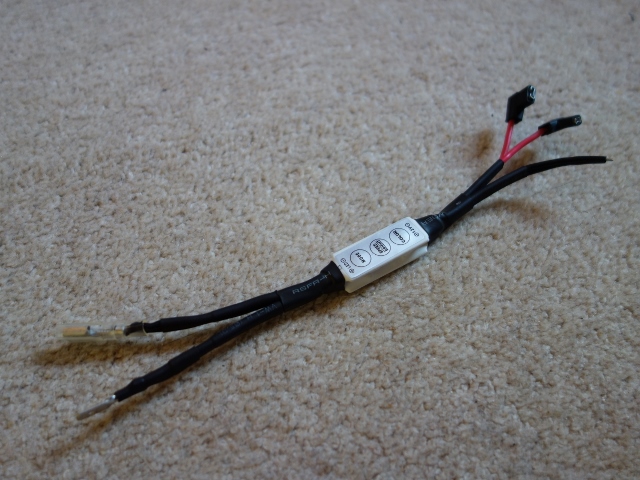
Unfortunately this task is not as simple with LEDs. The light output for two ‘identical’ LEDs is not as predictable simply by reducing the voltage drop across them. The only reliable way to dim LEDs is rapidly switching the LED on and off. Above a certain switching frequency, the human brain cannot differentiate between when the LED is on and off. The perceived brightness is then the relative percentage of time the LED is on during one switching cycle.

Fortunately it’s possible to purchase small LED control units to perform this function. My initial trials using LEDs found that, without on/off switching, the light output was too great. Therefore two LED control units would be needed to control the brightness for both the Bright and Dim settings.
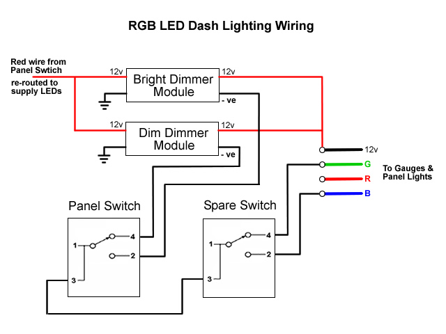
The other key difference, already mentioned, is that the 12v supply voltage is always connected. The individual LED colours are turned on by connecting their earth lead to a ‘floating earth’.

Note: this ‘earth’ is different from the car earth as when in dimming mode it will switch between 0v and 12v.

Green/Blue switching
The ability to switch between green and blue lighting would require the complete rewiring of:
i) the panel switch to select either the ‘Bright’ or ‘Dim’ earth connection from the respective LED control module (rather than provide the 12 volt supply)

ii) the spare switch to then connect the selected earth to either the green or blue lead. After a few trials, I settled on the wiring diagram shown.

Both LED control modules are connected to the loom’s Red supply wire from Fuse 5, which is disconnected from the Panel Switch, and the car’s earth. The positive LED outputs from both control modules provide the 12v supply to the RGB cable.

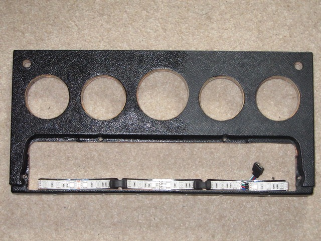
New wiring is then needed to between the two switches for the earth connections to either the Blue or Green LED lead. Finally the gauges and switch legend LED strip are daisy chained together with 4-core RGB cabling.

Switch Legend Strip
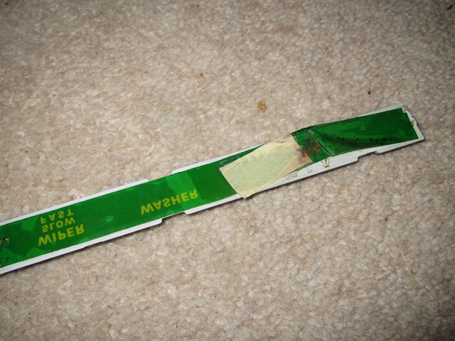
The switch legend is normally lit by three bulbs mounted in convex reflectors approximately 10cm in length. The green hue was achieved by a plastic green tape glued to the rear of the legend strip. However this has faded so it was now more of a mucky yellow colour. The tape was removed as the colour would now be provided by the LEDs.

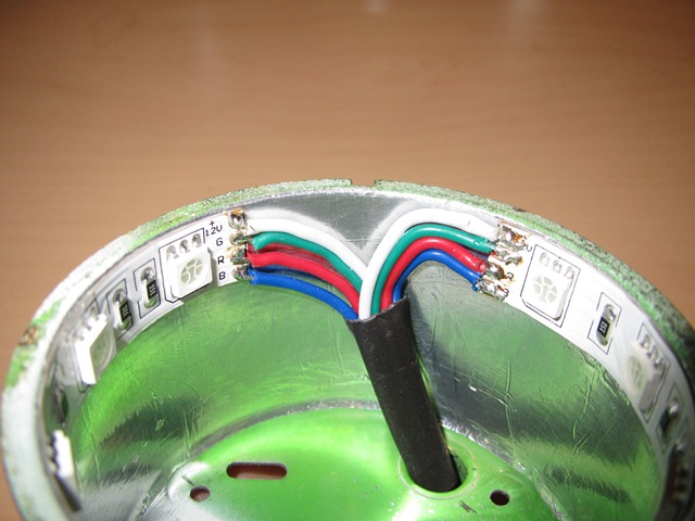
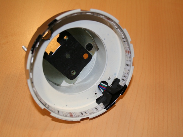
Green tape provided legend colouring LED strips fitted to legend reflectors
The green colour of the backlighting was obtained by a coloured plastic strip Installation of the LEDs for the illumination of the switch legend.

{Note: the dash photo was taken midway through being cleaned/treated with Gtechniq Trim Restorer C4 – hence the half and half look!}

Dash Gauges
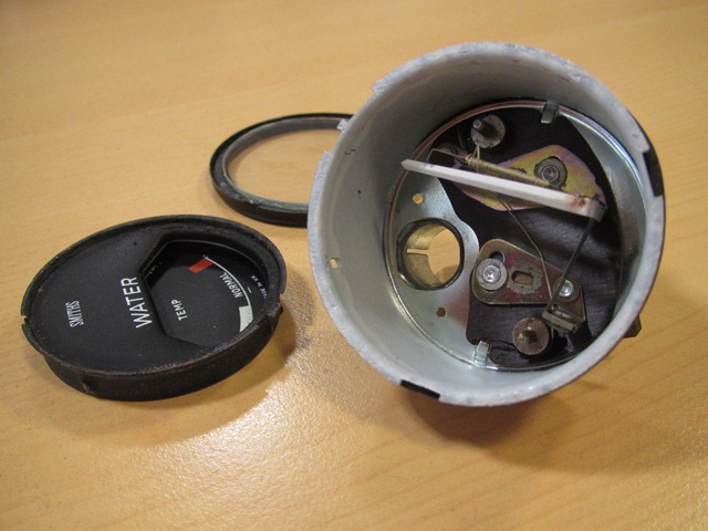
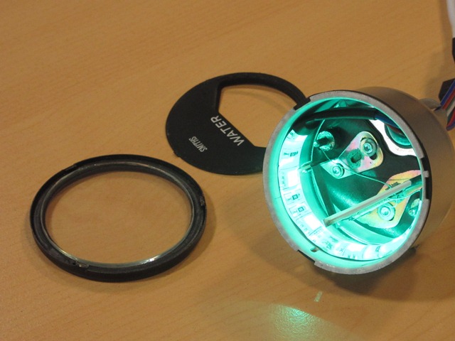
The seven gauges are all opened by rotating the rim until tabs on the rim align with cut-outs in the housing. This enables the rim and glass to be removed to install the LED strips.

The internals of the smaller four gauges (water temperature, oil pressure, fuel and battery) are very similar where the mechanisms are permanently secured to the housing. These mechanisms are quite delicate so the dismantling and insertion of the 10cm LED strips needed to be done with some care.

These gauges have a face plate which has to be eased away from the underlying cup, which has the gauge’s scale printed on it. A small screwdriver can then be inserted under the rim of the cup to prise it away from the housing. Once loose, it’s a matter of rotating the cup to clear the fragile needle.

Six dash gauges and clock Face plate & cup removed LED strip inserted from the rear

It’s very easy to inadvertently solder the RGB earth contacts together so it was well worth testing the operation of the LEDs before rebuilding the gauges.

The clock proved to be more difficult even though the entire clock mechanism comes out with the face. It’s slightly larger than the other gauges and so can accommodate a 15cm strip. However the clearance between the housing and the clock mechanism wasn’t sufficient due to the clear, waterproof coating. This had to be peel off to fit.

Removing the waterproofing Cabling was a tight squeeze Comparing brightness of colours

The entire mechanisms for rev counter and speedometer are also removed with the gauge face, which allows unhindered access to stick the 35cm strip to the perimeter.

Rev counter housing Cable pass through bulb opening Testing prior to rebuilding

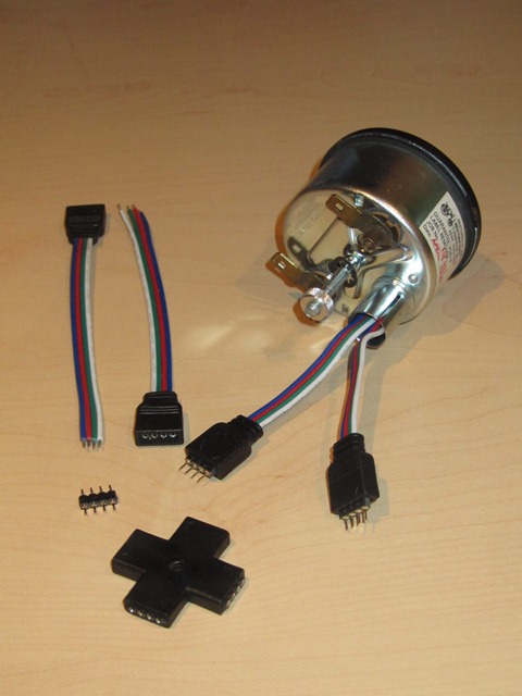
The downside of having the ability to switch between the two colours is it requires multi-core cable and so the installation is not so discreet. Even so, it will all be hidden from view once in place.

My first attempt was to use standard RBG cables and connectors but these provide to be temperamental and unlikely to stand the test of time. I therefore changed them to larger plug and socket terminals with internal, mini spade connectors which were also held together by a clip.

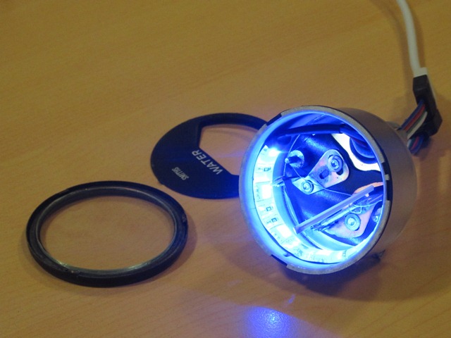
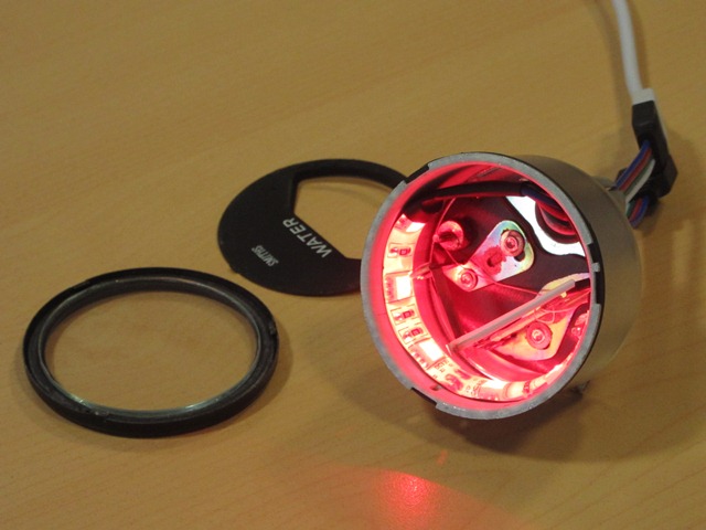
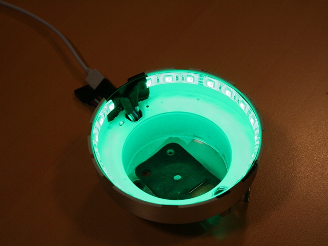
RGB connectors were unreliable Blue illumination without dimming Switched to green illumination

The other LED lighting was to illuminated the boot when the bootlid was opened. Two 25cm pure white LED strips were stuck to the underside of the tonneau top panel. Power was provided by running a wire from the permanent Brown fuse terminals and switched by a micro switch attached to the boot hinge.

Would I do the same upgrade again? Definitely not! Possibly just installing a single colour LED strip but the ability to switch between green and blue lighting resulted in unnecessary complexity. Just because it can be done, doesn’t mean it should be done!

 Posted by at 8:43 am
Feb 092015
 

Even though the engine was started last year, there were a number of outstanding issues and tasks to complete the fuel system. The most concerning was the new fuel tank didn’t fit! At the time, it was just left in situ and the fuel lines connected while the engine was fired up. Refitting had to wait.

Carburetter Overflows
First, however, was the replacement of the three carburetter overflow pipes. At some stage these had been replaced by shorter pipes. Functionally there was nothing wrong with them but they should come together near the oil filter and be held in place by small clip.

The short pipes will be replaced New pipes from Burlen Fuels
Either short overflow pipes had been fitted or the originals had been cut short  New overflow pipes are available from Burlen Fuels – very expensive for what they are!

Everything is available from Burlen Fuels although they offer two lengths of overflow pipe: 19” and 25”. The length of the shorter pipe would have been marginal for the rear carburetter so I opted for 25” pipes …. just in case. With hindsight, 19” pipes should have been ordered for the front two carburetters as the distances are much shorter.

I had decided to replace these once the engine had been fitted. While it would have been much easier to shape them when the engine was sitting on its trolley, I was concerned that guesstimating suitable clearances to engine frames etc would be too easy to get wrong.

Several hours later, ready for fitting The clip securing the ends of the pipes
 Several hours later, the pipes were ready for fitting

The only slight difficulty was the overflow for the rear carburetter as access was limited once it had been shaped. The jury is still out on whether it would have been better to do this job with the engine out!

New bulkhead fuel line
Another fuel problem encountered when the engine was started was the fuel line had gone into the filter housing cockeyed, causing it to cross-thread and leak. The temporary solution had been to reverse the fuel filter however the root cause was the bulkhead section of pipe, which needed to be remade.

These earlier troubles had been caused by a combination of the pipe not being square onto the filter housing and the brass fitting supplied in the fuel line kit. The fitting had an un-threaded shoulder section which then only allowed a turn or two of thread to engage before it bottomed out on the olive. A replacement was found that was threaded to the end.

The vacuum tank needed to be removed to provide sufficient access to offer up the new pipe as it was bent into shape. I wasn’t happy with the original routing of this section of the fuel pipe, as the P-clip securing it to the bulkhead, pulled the pipe hard against the paintwork where there is an ‘X’ indentation in the toe-box.

Original routing Now routed higher on toe-box Upturn no longer fouls bodywork

By inverting the P-clip, so the pipe was supported by the clip rather than being hung from it, the pipe is routed above the ‘X’. The other problem that was cured from my first pipe attempt was the length of the downward run to the union had been cut too short, causing the upturn bend to hit the bodywork.

Installing the fuel tank …. 4th time lucky!
I take my hat off to the original fuel tank fitters, who must have developed quite an efficient technique for getting the fuel tank in place on the production line. Although, with trails and tribulations I had trying to get the tank securely fastened, it was becoming a less daunting challenge with each fitting attempt. Perhaps there is some truth in the joke about E-Types being built up around the fuel tank!

First a few minor tasks were completed. The sump was checked for pinholes as it is prone to corrosion and fitting the missing metal fuel filter at the base of the pick-up pipe. The tank and surrounding bodywork was then covered with plenty of sheets and masking tape to try and minimise the damaging the paintwork.

Fortunately sump was pinhole free Pick-up pipe – now with filter

The initial problem is the aperture of the boot space is less than the width of the seam-welded lip around the circumference of the tank. Tilting the front edge of the tank downwards doesn’t enable the lip at the rear to clear the flange for the boot boards.

There’s a gap in this flange where the boot lock attaches. So the only option I could see was to remove the lock and then tilt the tank sideways, feeding the lip through the gap vacated by the boot lock.

The most obvious approach was to raise the right side of the tank and feed it down to the left since the tank occupies the left side of the boot. However this first attempt failed as the sump attachment is proud of the base of the tank and comes into contact with the floor strengthening sections, halting progress.

So the opposite was attempted, feeding down to the right. The aim was then to shuffle the tank all the way across to the left once the flange had been cleared.

Yet just as it was nearing that point, it fouled somewhere else! It wasn’t immediately obvious what was causing the problem but eventually it was traced to the clip for the boot board. Fortunately it’s only riveted in place and could be removed.

The offending boot board clip Eventually the flange was cleared

Finally the tank was below the flange and could be manoeuvred into position once the various filler and breather pipes were attached. The boot lid drainage pipe caused quite a bit of aggravation as it had a tendency to spring out of place and push the tank away from the mounting points.

Corner bracket should
have captive nut
Breather tubes for
later S2 tanks
So near, yet so far

However, until now, I hadn’t noticed the replacement forward mounting bracket simply had a nut welded to it, rather than a captive nut within a cage. The lack of adjustability provided by a captive nut meant it was impossible to get the distance between the two leftmost mounting points to match those on the tank.

One of the mounting hole in the tank had to be enlarged by around 3mm to get the tank to fit The tank had to come out in order to enlarge the mounting hole in the tank by a couple of millimetres. Unfortunately I wasn’t able to rig up something to measure the difference in centre distances with any degree of accuracy. The tank was re-fitted but it was still a millimetre out, so it was back out for some more fettling.

This time it fitted! Well two of the three mounts did. The third bracket is moveable as it can slide in elongated holes and so would be doddle in comparison. How wrong could I be!

The original bracket had one stud missing and two of the other studs had lost most of their thread due to corrosion. It didn’t feel it was worth trying to salvage it as new ones are inexpensive. So I made the mistake of buying a reproduction bracket – not once but twice!

Damage to original bracket Neither repro brackets were usable

The first wouldn’t fit because the studs were too far apart to mate with the holes in the bulkhead. To make matters worse, I only found this out after it was powder coated. The second was ordered from a different supplier. The studs were in the right place but much smaller diameter. However, as with the previous bracket, they both just had a nut welded in place rather than the captive nut.

This mount requires both lateral and fore/aft adjustability to have any chance of alignment with the bolt. Lateral adjustment is provided by the elongated holes for mounting the bracket. The movement of captive nut provides the fore and aft adjustment. Neither of the repro brackets were useable.

Its times like this that I do get frustrated with all the suppliers – it’s just lazy ‘that’ll do’ mentality and often it would be as hard to get wrong as it would right. Although I really should have spotted the differences when they were purchased. The original one will be repaired, which is what I ought to have done in the first place. Another lesson learnt!

Fuel Sender – stumped but fixed
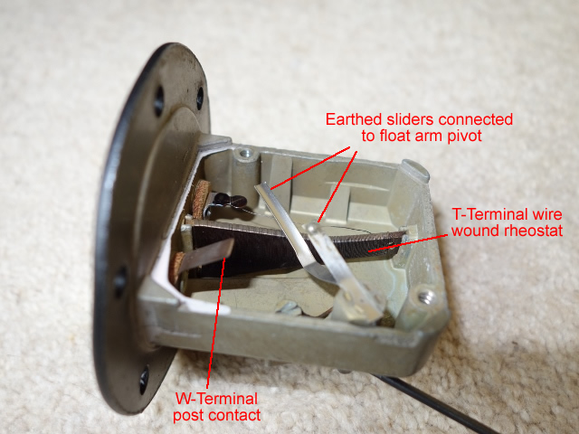
For some reason the low fuel light on the dash wasn’t working, yet the fuel gauge was fine. The fault was traced back to the fuel sender unit, which has a removable cover plate. So it was easy to gain an understanding of how it worked to control both the fuel gauge and warning light.

W & T terminal mechanisms Low fuel light contact strip

As would be expected, the unit uses a rheostat to vary the voltage drop across the fuel gauge and the warning light is simply a contact switch. However I hadn’t realised they were two completely separate circuits, sharing a common earth – the sender unit housing.

As the float arm rises and falls with changes in fuel levels, its pivot rotates through approximately 80 degrees. Two slider contact arms are attached to the pivot within the unit and therefore follow the same arc. They are also in contact with the sender housing and so are the electrical contact to earth.

Fuel Gauge
One of the sliders runs along the edge of tapered coil of resistance wire which is connected to the exterior T terminal. When the tank is full and the float is raised to its maximum, the full length of resistance wire lies between the slider and the T terminal – a total resistance of 196Ω.

When the tank is nearly empty and the float is at its lowest, the slider will have moved shortening the length of resistance wire between the two. At empty, the rheostat resistance is 18Ω. The fuel gauge is calibrated to display Full and Empty for these two resistance values.

Low Fuel Light
There’s a copper contact strip on the inside of the cover plate which has a small diagonal break in the copper so the two ends are electrically isolated from each other. The W terminal, connected to the gauge, makes permanent contact with one end.

When the tank is full the second slider arm is in contact with the other end of the strip and moves towards the W terminal contact as fuel is consumed. The slider eventually moves across the gap making electrical contact with the W-terminal, completing the path to earth and switching on the warning light.

I couldn’t work out why it wasn’t working. The multi-meter confirmed the internal connections were working correctly. Yet the switching wasn’t evident at the external spade connector. It didn’t make sense as a metal rivet connects the internals with the external spade terminal.

Checking with the multimeter confirmed that somehow the rivet and the external spade terminal were electrically isolated from each other. A dab of solder solved the problem but I still can’t fathom how they could not be in contact with each other.

Once it’s up and running, I’ll fill from empty to find out how many litres of fuel are in the tank when the light comes on.

The tank has since been filled from empty and it takes exactly 12 litres (2.6 gallons) before the warning light goes out. So there should be around a 50-55 miles range once the warning light comes on.

Jan 132015
 

Jaguar made several changes to the clutch slave cylinder during the production of the E-Type which appear to have caused a fair amount of confusion amongst owners, myself included.

The slave cylinder details from the Jaguar literature are:

  • S1 to engine 7E4606 – short 80mm adjustable cylinder (part C21470)
  • S1 from engine 7E4607 – 95mm hydrostatic self-adjusting cylinder (part C24145)
  • S1 from engine 7E18356 (7E55558 for 2+2) – reverted to adjustable cylinder (part C29801)

The difference being the adjustable cylinders require a return spring and bracket to pull the fork back, so the piston is at the mid-point. The hydrostatic, self-adjusting cylinders must not have the return spring fitted. Either type can be fitted to any of the range, so you just need to know which type is fitted to determine whether to fit a return spring.

As a result, the length of the slave cylinder is often used to differentiate between the two types. A 95mm unit was supplied when I ordered a replacement C29801 cylinder and the suppliers assured me it was correct.
I made the assumption, from all the forum discussions on the subject, that I must have a hydrostatic unit and therefore didn’t include the return spring when it was fitted it to the transmission, prior to installing the engine.

It wasn’t until another S2 owner who was going through the same issue was able to confirm the 2nd version of the non-hydrostatic cylinders was 95mm, not 80mm, with the original Lockheed part having markings 3232 648C. This matched the markings on my replacement cylinder and also on the one that had been removed during the dismantling, which was fitted with a spring.

My conclusion was that the return spring will need to be fitted after all. Another recommendation was to replace the mounting stud by 5/8″ UNC x 1″ socket head bolts. This will make later removal easier as access is severely restricted.

So another task to add to the ‘To Do’ list!

Jan 092015
 

Once it became clear that the September target for obtaining an MOT would be missed (albeit with a stripped out interior), the pressure was off. With the cold, dark days of winter setting in, holidays in warmer climes became preferable to working on the car and so the momentum lost.

The new target being the spring, once the last traces of road salt have gone. Just in time to sort out any niggles and put a few miles on the clock … before a mooted caper to the Monaco Grand Prix. It would be a fitting inaugural tour! Apart from the lack of trim, the car appears to be nearing completion. However looks are deceiving and the ‘To Do’ list is still alarmingly long. So I’ve got to get cracking!
I’ve not been looking forward to installing the trim as it’s notoriously fiddly and something I’ve not tackled before. It’s the part everyone sees so it has to be done well. After all the effort so far, a poor job would not suffice! Further procrastination was required under the guise of trim planning ….

I settled on the following order of events:

  • Door A-post rubber seals
  • Fit and align the window frames and drop glass
  • Door B-post seals (the sill seals will have to wait until after the sill vinyl has been fitted
  • Trial fit hood frame to ensure the glass seals against the hood’s cantrail rubber seals
  • Vinyl trimming – sills, lower rear bulkhead and wheel arches
  • Sill seals and chrome finishers
  • Underfelts followed by hardura panels, vinyl covered finishing panels and carpets
  • Centre console and radio panel
  • Under-dash felts, hardura and cards
  • Install the seats!
  • Install inertia seat belts in the boot space

I’ve decided it was best to leave the fitting of the hood and tonneau cover to the experts, Suffolk & Turley, who supplied the trim kit. Finally, once the car is returned, I’ll fit the door cards and boot trim.

Door Seals
New door rubbers were obtained from SNG Barratt. However I wasn’t happy with the A-post and sill seals as, not only were their cross-section profiles noticeably larger than the originals, they were made of a much harder foam rubber.

Other owners have posted issues with poor quality seals leading to ill-fitting doors which need slamming just to get the door to latch. The general consensus on the E-Type forum is to source all the rubber seals from COH Baines so a new set of door seals was duly ordered. I would thoroughly recommend doing so as they are much closer to the originals and made from a softer foam. I believe SNG Barratt have subsequently started to source many of their seals from COH Baines.

Profile comparison of sill seals Darker Baines rubber is thinner & softer

Hutsons had pre-fitted the doors to the bodyshell, so the door strikers and locks were correctly set and panel gaps were all spot on. However the fitting of the A-post seal requires the door to be removed to provide sufficient access. So the outline of the door hinge was marked out with masking tape to aid re-fitting.

Position of hinge marked with masking tape Tape was also used to trial fit the seals

Before removing the door, the A-post seal was trial fitted by taping it in place. Adjustments were made until the door could be closed easily without too much resistance. Some trimming of the seal was needed where it has a protrusion at the base of the A-post.

Initially I had cut the seal exactly to length but the door felt a little hard to close. It is rather subjective at this stage, without the resistance of the other seals. I wanted to keep the additional force needed to compress the A-post rubber to a minimum.

Being nearest the hinge, it requires considerably less force to compress this seal so any noticeable increase now would be magnified once the B-post seal is fitted. Being made of a softer foam allowed it to be cut marginally shorter and then stretched to reduce its cross-section, therefore reducing the resistance.

Once I was happy with the fit, it was time to remove the door to bond the seal in place with the Alphabond AF178 high temperature contact adhesive I’d used for the Koolmat.

The advice for getting the best bond and avoid the seals pulling away is to clean them with methylated spirit to remove any traces of the mould release agents and roughen the surface to be bonded with sandpaper. The contact adhesive should then be applied in three steps:

1. Apply a layer to the rubber seal and leave until tacky
2. Apply a layer to the seal channel and again leave until tacky
3. Apply a second layer to the rubber seal, once the first layer has gone tacky, and when this second layer becomes tacky, push the seal into the channel

I found it easier to tackle the A-post seals in two stages: first from the triangular section at the base of the A-post up to the top of the A-post and then the lower section down to the sill. For the lower section, I inserted a small diameter rubber hose into the gap in the rubber seal before securing it with masking tape. This worked really well in holding the rubber against the sides of the channel until the adhesive had dried.

Top half of A-post bonded first Once dried, the lower half was tackled

Everything was held in place for 24 hours with masking tape and then any excess adhesive removed. First softened with a cloth soaked in white spirit and then carefully wiped away. There were some areas where the adhesive had lifted away from the paint work so these required some touching up and re-bonding. Another tip I was given was to use Dum-Dum style body putty to fill any small holes or gaps.

Previous hanging of doors had been a frustrating and fiddly experience so I only wanted to do it once. The weight of the various internal door mechanisms is not insignificant. So I wanted to have the doors at their full weight before setting all the panel gaps, thus avoiding the risk of them dropping by adding them later.

The doors were refitted to their marked positions and the door internals completed (see below). Only then could the fine adjustments be made to get the panel gaps right. As would be expected, the doors had dropped slightly under the additional weight of the internal mechanisms and so the hinge position within the door had to be adjusted to compensate. A trolley jack was used in place of a suitable assistant to support the door while fine tuning the panel gaps.

Solo door hanging Bonding the bonnet landing seal

I could then move on to the B-post seals, which were tackled in the same manner as the A-post seals. Although these were fitted in one go and needed the bonded edge to be sanded down in places to enable the door to close without undue force. Hopefully, once the final sill seals are added, the doors will still shut easily. If not, it might be a case of re-doing all the rubber seals and re-hanging the doors!

Finally the bonnet landing rubber was bonded in place while the adhesive was out. It was also more manageable by tackling this in two stages.

Door internals, window frames and drop glass
The next task was to complete the fitting of the door internals and drop glass. The initial fitting of the frames produced very different results. The frame on the driver’s side was fairly close and possibly needed a shim added at the rear to bring the leading edge parallel with the A-post.

The passenger side was way off! The leading edge was angling away from the A-post, by approx. 6-7mm at the top, and this was with the rear of the frame raised by two thick shims. Something was wrong!

The driver’s side frame was fairly close However it wasn’t the case for the passenger side!

Suspicion fell on the geometry of the window frame, which had been re-chromed. The re-chroming process involves polishing the underlying plating before the chrome layer is applied. This can cause distortion due a combination of the pressure applied to polish the part and the resulting heat that is generated.

Sure enough, when I tried to fit the drop glass, the regulator channel the glass sits in would not fit into the frame. It was too long, front to rear. I then used the driver side drop glass as a comparison – it’s length fitted fine! Much head scratching ensued … it must be the reproduction regulator channel.


Difference in angles of
rear regulator channels!

Overlaying the two revealed the problem. The angle of the rear of the regulator channel was way off on the passenger side. After much cursing of reproduction parts (that enable us to keep these cars on the road!), I set about removing the glass from the regulator channel. Gentle prising with a screwdriver would only end in tears as the rubber grips the glass very well.

Fortunately a small amount of penetrating oil worked wonders and the glass came out surprisingly easily. The rear edge was bent into the correct alignment and the glass and rubber re-fitted. Longitudinally it now fitted the frame.

Alas the same couldn’t be said for the width. The leading edge of the glass sits in a flock lined rubber channel. While at the rear, the short trailing edge of the regulator channel sides metal on metal in the window frame. The width of the repro ones were too wide.

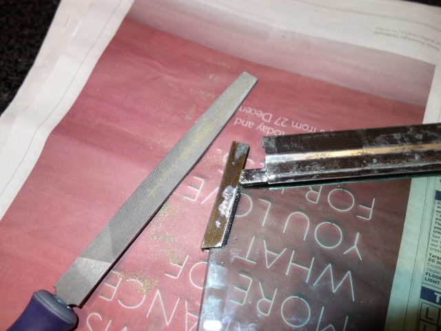
Both regulator channels required a fair amount of filing to reduce their width so they slid easily within their channels. It was only once I started filing that I realised the rear section was made of brass but had then been zinc plated. When I had first fitted them I had cursed the fact that the reproduction parts hadn’t used brass, as in the originals!

Both regulator channels needed filing Regulator channel were polish to reduce friction

Once they slid easily within their channels, I decided to polish both the regulator channels and the window frames to reduce future binding problems. Some Shin-Etsu Silicone Grease will be applied to the seals and mechanisms before the door cards are fitted.

Attention returned to the passenger side window frame as the glass did not slide cleanly all the way down. The reason was found to be cause by the chromed leading edge of the window frame being bent out of alignment – both rearwards and outwards! Fortunately gentle persuasion allowed it to be re-bent close to its original shape.


The width of the channel
allows the glass to rattle

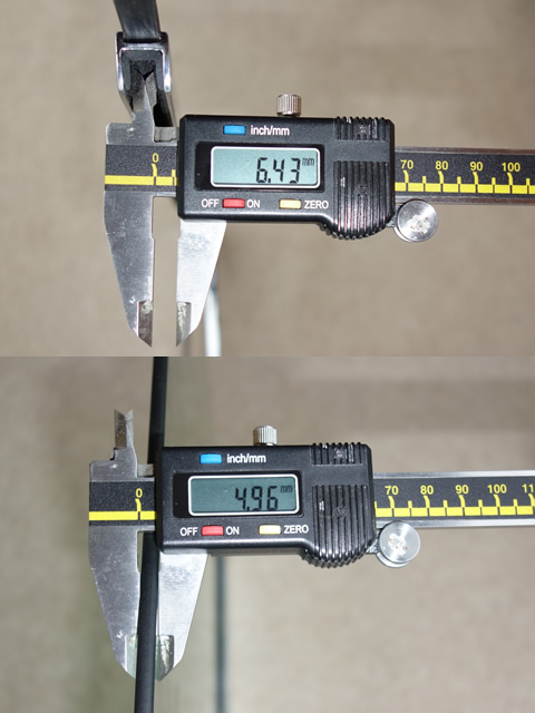
I thought this would be the end of my window woes. How wrong could I be! The flock lined front channel comes in two sizes for 4.75mm and 6mm glass. I had the latter but, with the glass being a little shy of 5mm, it allows the window to rattle within the channel. However, the smaller size would cause binding issues.

At this point I chuckled as I’d been in correspondence with the Jacksons whose E-Type refurbishment exploits have been covered in the E-type magazine. They had already experienced almost identical restoration issues, not just in the fitting the drop glass! But now I think I understood the issues they had encountered with the flock lined channel.

I also purchased some lengths of thin rubber strips to pack one side of channel in the window frame before inserting the flock lined rubber alongside. This closes the channel slightly to guide the glass without causing it to bind or allowing it to rattle.

Building up the door innards
The first task was to fit the door handles and then set the gap between the push button plunger and the lock/latch striker lever to 1/32”. This should ensure that the latch is fully released when the push button is pressed. Adjustments were made by slackening the lock nut on the plunger, adjusting the setscrew and then nipping up the lock nut.

Setting the plunger-latch gap Allen key fixing lever position Setting the handle/lock link

The fitting of the link between the door handle lever and lock requires the lever to be fixed in position. Aligning a hole in the lever with a hole in the rear casing allows a small Allen key to be inserted to lock the position. The link is then fixed to the handle lever. Its lower end has three overlapping, fittings holes and it is simply a matter of picking the best fit to the lock lever.

The regulator springs had been removed prior to the regulators being plated and were showing signs of rusting. They were shot blasted and blackened with a four stage process supplied by Caswell UK. The process only takes approximately 30 minutes but the final stage requires the component to be dipped in oil and then left to dry overnight. I’m not convinced how durable this finish will be and its ability to stop future rusting so it will be packed with grease prior to fitting the door cards.

Regulator springs prior to blackening Spring after blackening and dipping in oil Regulator wound to refit spring

With the springs fitted, the regulator could be inserted from above, followed by the two brackets to secure the bottom of the window frame to the base of the door. These brackets are moveable on their mounting stud so the lateral position of the top of the drop glass can be adjusted. These were only hand-tightened as they will need adjusting when the hood frame is trial fitted.

Regulator was fed in from above Rear window bracket Front bracket is shorter

I found it easiest to insert the window frame by first tilting it forward and inwards at the top until the front stud has cleared the door frame. It was then secured at the top in three places, where two screws pass through the window frame and door frame into a thin plate below. Shims can be added as required between the window frame and door frame to either raise the whole frame or tilt it so the frames leading edge is parallel with the A-post.

(Although when I mentioned this to E-type expert Ken Verity, he suggested the need to tilt the frame with shims would suggest the frame might not be 100% true. This may cause window binding problems so needs to be checked before continuing. Distortion is typically caused by people use the glass or frame to pull themselves from the car.)

Clearing the front stud Fixing for top of the window frame Regulator fitted and at full height

The external glass weather strip needed to be clipped onto the door skin before inserting the drop glass because there wouldn’t be sufficient access once the glass was in place. (Update – I was jumping the gun here and had to remove it! I had forgotten to fit the chrome door flash so had incorrectly assumed the weather strip was attached to the lip of the door skin. I think it needs to be clipped to the lip of the chrome flash!) The window regulator needs to be raised to its maximum height in order to engage it with the drop glass channel.

Engaging drop glass with regulator Almost there – drop glass fitted Door remote control attaches to lock

Next is the door remote control. Its link arm is attached to the door lock to enable the door to be opened by the interior lever. A wavy washer is fitted between the lock and the link arm to take up the free play. The square nuts fitted in the regulator channels set the maximum height of the windows but these will wait until the trial fitting of the hood.

The doors were also fitted with a bracket that had a semi-circular foam section bonded to it. This is to dampen vibrations in the remote control link arm. Unfortunately these were missing on my car but once again RM & J Smith came to the rescue for obscure, missing parts. They had a pair of original brackets that would need tidying up and the foam replacing.

Finding suitable replacement foam was not an easy task! Eventually I found Seals+Direct who offered a 1” diameter 1/2 round cord of expanded Neoprene (part ENHC94) which was ideal. Strips were bonded to the brackets with the Alfabond AF178 contact adhesive.

The small aluminium seal blocks need to be fitted to the trailing edge of the doors before the door rubbers are trial fitted because these compress the upper part of the B-post seal.

Bonding new rubber Damping brackets fitted Finally the sealing blocks

The last check was to ensure the height of the door frames against the A-post was even on both sides. The driver side was flush with the A-post cap while the passenger side was 1/8” lower. An equivalent depth of shims was added under the window frame edge to bring the frame up to the same level.

Driver’s frame flush with A-post Passenger side was 1/8” lower!

What should have taken a day or two ended up taking well over a week! Next will be the refurbishing of the hood frame ….

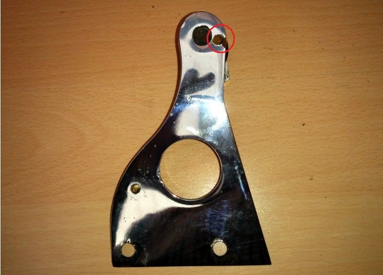
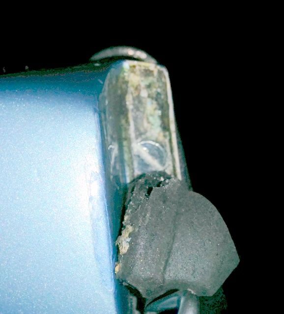
Update: a recent post in the ‘factory fit’ thread on the E-Type forum identified that the chrome bracket for mounting a hard top is secured at the top by a 12-28UNF cheese head screw. This screw passes through the channel for the B-post seal into the rear of the chrome bracket (circled in red below). Therefore the seal needs to be fitted after bracket and the bracket is fitted after the interior trim.

I will therefore have to undo my fine work and detach the top 3″ or so, by softening the contact adhesive with white spirit, and re-attach once the interior trim is completed.

Hard top securing bracket Securing screw behind B-post seal

Images courtesy of E-Type Forum

Nov 132014
 

Time pressures delayed the full electrical shakedown testing until after the engine was up and running. Power is only required to the ignition and fuel pump circuits to start the engine so all the other fuses were removed. Having said that, I did end up fitting the fuse for the instrument voltage regulator in order to obtain oil pressure and temperature readings while the engine was running.

The other fuses were now fitted in turn, stopping to test each of the components they fed, before moving on to the next fuse. The resulting snagging list was encouragingly minor:

  • The main beam can’t be flashed from the indicator stalk
  • The original hazard flashing unit is on the blink!
  • The brake fluid warning light isn’t coming on
  • The wiring to the rear brake and sidelights have been crossed over
  • One of the cooling fans is a little noisy and spins the wrong way!
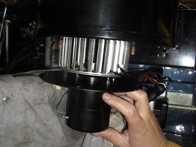
  • The heater fan is making contact with the housing
  • Neither the washer or wipers work
  • Only one horn worked

Overall I was quite pleased with that for a first test. Especially as it was the first time the cooling fans and wiper motor had been tested since I rebuilt them and the washer, wiper, brake fluid warning light and horn were all simply missing earth connections. So easily solved.

Indicators and hazard lights
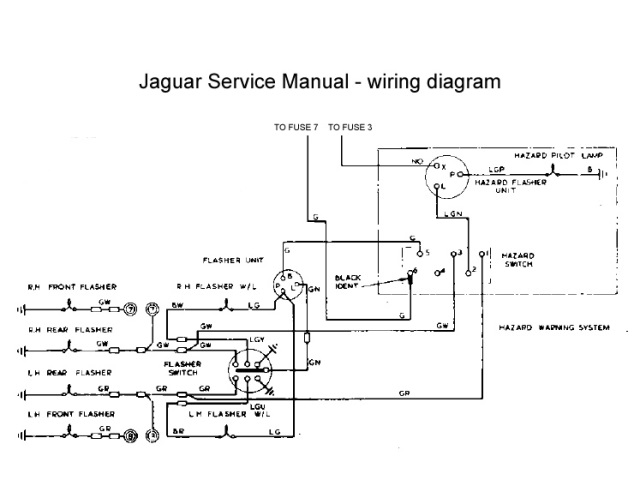
There was a fair amount of head scratching when wiring up the hazard warning light switch. The part number identified it as a hazard switch from an XJ6 and its pin connections conflicted with those in the Illustrated Parts Manual!

Hazard wiring diagram Hazard switch wiring

So I attempted to go back to first principles (or my understanding of them!) to work out the correct wiring. The one thing that was puzzling me was why separate indicator and hazard flasher units were used. They are essentially performing the same role – converting a constant DC supply into a square wave, with a suitable duty cycle to provide the correct flash duration and frequency.

The light bulb moment came when reading the requirements to pass an MOT. The hazard lights must be able to operate without a key in the ignition while the indicators are only powered when the ignition switch is on. The other difference is the power rating as the hazard unit needs to draw more current drive both sets of indicator lights at the same time.

The duty cycle of the unit is achieved by a bimetallic strip which expands and contracts depending on whether current is flowing. When the indicators are on, the current generates heat in the two metals, which expand at different rates. This causes the strip to move away from its contact and break the circuit. Without a current, the strip rapidly cools and the circuit is re-established allowing current to flow once more and the process to repeat.

Therefore the flashing frequency or ‘duty cycle’ is directly related to the rate of expansion/contraction of the bimetallic strip, which is a function of the current flowing. This is why modern LED indicator bulbs often do not work on classic cars as they draw far less current and therefore may not generate sufficient heat to switch the traditional units. Modern transistor based units are available to overcome the problem.

Therefore the switch needed to have the following connections:

Hazard switch in OFF position

  • Indicator flashing unit is introduced into the circuit (the two green wires are connected)
  • Hazard flashing unit is cut out of circuit (connections between the LGN, GR & GW wires are broken)
  • The indicators can then be operated via the switches built into the indicator stalk

Hazard switch in ON position

  • Indicator flashing unit is cut out of circuit (by removing power to its green wire)
  • Hazard flashing unit is introduced (by connecting its LGN output to both the GR & GW indicator feeds)

The only problem was the random frequency of the hazard flashing which was easily solved by fitting a new flasher unit.

Cooling Fans
The S2 cars have an otter switch to turn on the cooling fans at its rated temperature and requires a special connector, which has been on back order for ages. A spare dash switch was rigged up in its place so the fans could be switched on and off at will, which would be useful when testing and tuning the engine. The first fan spun up and ran smoothly and quietly, which was very pleasing, as they hadn’t been bench tested after their refurbishment.

However the operation of the second fan was noisier because the blade was not quite square on the armature shaft, causing vibrations. Removing it was a fiddly process with the engine bay completed so I was cursing not having bench tested it!


But more importantly, the motor was rotating the wrong way, pushing air forward towards the radiator rather than drawing air through it. Its effect would be worse than having no fan at all. When travelling at speed there would be a natural flow of air through the radiator. Having a fan blow against this flow would reduce the cooling ability.

It is rather odd because reversing the supply polarity of series wound DC motors (and indeed shunt wound motors) does not reverse the direction of rotation. The only way to rectify this would be to reverse the connections on either the field or the rotor windings (but not both!).

The rotating force (torque) on the armature shaft is the result of the interaction of the magnetic fields of the armature and the field winding – opposite poles attract, like poles repel. The directions of these magnetic fields are dependant on the direction of the current following through them.

Therefore changing the polarity of the power supply does not reverse the direction of rotation because both the field and armature currents will be reversed and therefore both magnetic fields. A double negative if you like, that cancels each other out!

The only practical option for these Lucas motors was to reverse the field winding, which was a very simple job.

Field wires just needed swapping All sorted – an easy soldering job

The fan now rotates in the correct direction to draw air rearward through the radiator. The fan was also re-seated to stop the fan vibrating so much.

I was trying to fathom an explanation as to why the motors were rotating the wrong way and then recalled that I had difficulty dismantling the two motors I’d acquired many moons ago, at the start of 2012. They were of the same design but had the fans mounted the wrong way round.

The person had indicated they were selling them as they had upgraded to modern fan units. However I suspect they had sourced motors from a different vehicle and noticed they were turning the wrong way. They had then mistakenly concluded mounting the fans the wrong way round would rectify the situation, rather than just improve their efficiency in making things worse!!

Wiper motor & Intermittent module


Intermittent control above
brake warning light

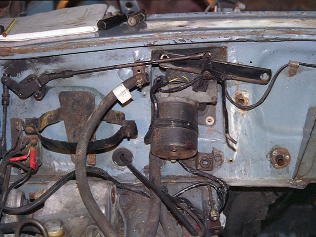
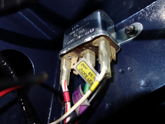
I’d decided to fit the Hella intermitted wiper module that other E-Type forum members had advocated. It works independently from the two speed wiper switch on the dash and the modification is reasonably discreet and reversible. The intermittent control uses the hole in the dash for the rear window heater on the FHC, which is blanked off on the OTS cars.

Like the hazard warning switch, the part number on the wiper motor switch also suggested it had originally come from an XJ6. The problem was the connected terminals were different to the correct switch (OFF 5-7, Normal 4-5, Fast 2-4) and so it was another case of trying to work out how it should be wired.

The combination of common sense and trial and error eventually produce the correct operation, which differed from the wiring suggested by the forum post. I’ve wired intermittent module into the ULG feed rather than the suggested YLG wire, which is for operating the motor at high speed.

At the same time, I also decided to add a jumper lead (with an inline diode) from the washer switch to the slow speed supply to the motor. Therefore the wipers now operate automatically while the washer switch is pressed. The diode is needed to stop it working in reverse, with the washer operating when the wipers are switched on!

Heater Motor
A complete new heater unit had to be fitted as the original had largely rusted away. The resistor, providing the dual speed operation, is riveted to the base plate of the heater motor. I’d foolishly assumed the new units would be supplied complete with the resistor already attached – dream on!

The resistor is sold separately and, due to the lack of clearance, requires the base plate to be removed from the motor in order to fix it. The wires are then soldered to the resistor rather than via spade connectors. As a result, the loom has bullet connectors built in, approx 6″ from the end of the wires, to allow the motor to be separated from the loom if it needs to be removed for servicing.

Resistor provides 2-speed operation Loom wires are soldered in place Fitting was tricky due to
the engine frame

However the looms didn’t come with the rather crucial two wires needed from the resistor to the motor terminals! The other issue came trying to re-fit the motor to the heater housing which had already been attached to the bulkhead. Removing it wouldn’t be an easy option as the cooling system had now been filled.

The reason the motor and fan cage couldn’t be fitted onto the housing was the base plate fouled on the engine frame. It was necessary to detach the fan cage from the motor by undoing the clamping grub screw. This allowed the cage to be fed up into the housing and then reconnected to the motor once the motor was clear of the engine frame.

The fan just had to be re-attached ever so slightly nearer the motor to cure the fouling problem found during the initial shakedown tests.

Alternator testing
The electrical component that I’d been putting off testing was the re-wired alternator. The modifications to the alternator were more far reaching than any of the other electrical work and so there was more scope for things to go wrong. Once all the other electrical issues had been resolved, I fitted the alternator belt and prepared to start the engine. Would it work or would it blow any of the other components?

Unfortunately I didn’t have a suitable ammeter to measure the theoretical maximum output of approx 60 Amps and so my testing was limited to measuring the voltage at the battery terminals with a multi-meter:

  • With the engine off, the terminal voltage should be approx 12.7v
  • When running at idle, the alternator should raise the terminal voltage to around 13.9v-14.3v
  • The terminal voltage should reach between 14.3-14.6v running at 2500 rpm

In theory if the alternator output drops from the last two levels then it points to the failure of one or more of the rectifying diodes. If it rises above 14.8v, then the 4TR voltage regulator unit is not limiting the maximum voltage and needs to be replaced to avoid overcharging the battery. However I also have to consider that any lack of output could also be due to the additional diodes introduced to self-energise the field winding.

It was a welcome anti-climax that the initial test appeared to be successful. Although I’ll need to do further checks to ensure it’s charging when the car is run for a longer period.

Jun 182014
 

My approach to the restoration has been to keep things as standard and drive the car for a while, before making any modifications. The two main areas that I have deviated from this are; fitting an EDIS Megajolt electronic ignition system and using the Mangoletsi cable throttle linkage.

The standard throttle has an inherent amount of free play due to the numerous joints in the linkage. The decision to fit the Mangoletsi throttle was aimed at improving the throttle response by removing this play and was based on the views of numerous forum members. My slight reservation was the appearance of the cables within the engine bay, as they arc from the pedal housing to the inlet manifold.


Mangoletsi cable throttle kit

The kit was ordered from SNG Barratt before the engine had been installed in the car which made the initial fitting of the components much easier! Although the completed inlet manifold and carburettors would be removed as a completed unit to fit the engine from underneath.

The kits are very well made and came in four clearly marked bags, and with detailed instructions. Most of the components are already fully assembled and pre-set so the installation is very straightforward.

The system uses twins cables to balance the load on the levers, providing a smoother operation, and the cables were the only components that would have to wait until the engine was in situ.

The first bag contained a linkage plate and gaskets which simply fits between the carburettors and the inlet manifold. The gaskets used are thinner than standard to compensate for the added thickness of the plate. The carburettors are re-fitted and then the kit’s spring carrier bracket is attached to the linkage plate. Pre-fitted to the bracket are the adjustable outer cable abutments which would be adjusted during the final set up.

Thinner gaskets are used Carburettor linkage plate

The carburettor’s standard SU throttle levers are replaced with ‘aircraft standard’ rose jointed levers, which have a quality feel to them, with a smooth and precise operation and no free play. The top rose joints are bolted to their respective levers on the shaft of the linkage plate. The only slightly fiddly part of the installation was synchronising the operation of the three carburettors. Although this was adequately covered in the instructions.

The kit’s spring carrier Hex adjustment for rose jointed tie rod

A jig plate is used to lock the linkage to a datum position to fit the rear rose joint tie rod, which has been pre-set to a length of 21mm. The front and centre tie rods are then fitted in turn and their lengths adjusted so the brass throttle plates all close at the same time.

An entirely new pedal housing is also included which allows the pedal position and length of travel to be adjusted to suit. Although it has been left at the pre-set 40mm of travel for now. Any fine adjustments will have to wait until the car is completed.

I should have been expecting it …. I then hit a major snag. It was all going far too well up to that point!!

When the pedal was depressed, the top of the pedal lever fouled the starter relay mounted on the bulkhead. I thought the relay may have been incorrectly mounted but old photos confirmed the relay was in the correct position. The new pedal housing was the problem!

Even mounting the relay on the wrong side of the bracket didn’t solve the problem. In fact it made it worse! The lever now just hit the relay bracket instead but also, it was then impossible to connect the wires to the relay. The reservoir bottles were in the way!

Early photo confirms correct position Relay mounted the wrong side But now the accelerator
just hit the bracket

In the end I contacted John Mangoletsi to find out why I was having problems fitting it. He was most helpful and was unaware of this issue, as it had not be reported to them before. A different kit is produced for 3.8 and 4.2 models and each has to be compatible with all the in-flight changes that Jaguar made at the factory.

It soon dawned on me that the relay position had changed right at the end of the S2 production run, as I found out when my wiring puzzle was solved. The relay moved to the engine bay bulkhead with the introduction of the ballast resistor. An additional relay loom was also added to wire in the relay in its new position. A loom that took ages to track down.

John Mangoletsi indicated that the kits were specifically designed to fit all the models and were sold as such. He kindly offered to visit to see the issue in person and come up with a revised solution for mounting the relay. One that could then be offered for the (few) cars which had a ballast resistor.


Starter relay relocated to its
original pre-Ballast resistor
position under the A-post

At this stage I realised I was being a bit dim! I already had the solution: the other change I was making was the EDIS Megajolt ignition system which removed the need for a coil and therefore the ballast resistor.

I could simply move the relay back to its original position on the bulkhead underneath the A-post and do away with the additional relay loom completely. Problem solved!

The final tasks were to connect up the cables once the engine was in place and tidy up the empty bulhead holes for the original linkage. I chose to fit socket head button screws rather than blanking grommets.

In summary, the Mangoletsi throttle cable linkage is a quality bit of kit and could probably be installed in a day or a lazy weekend. I will have to make a point of driving a standard car so I can feel the difference to make sure it was worth it!