Nov 122013
 

The horns suffer a harsher environment that a lot of the other component as they're located low down at the front
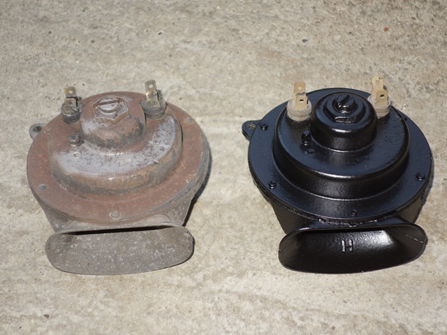
A pair of Lucas windtone 9H horns was fitted to the Series 2 E-Type, one emitting a high tone and the other the low tone. The excitation of the air column is achieved by vibrating an internal metal diaphragm, with the frequency of vibration and the shape of the horn snail or trumpet determining the note produced.

The switching frequencies are carefully chosen to produce a major third musical interval (spanning 4 semi-tones). Together they set up beat frequencies producing a tremolo affect and a perceptibly louder sound. In the case of the 9H, the low tone switches at 392Hz and the high tone around 494Hz, producing a G and B respectively.

Great in theory, however both my horns were stamped with an ‘H’ on inside of the trumpet indicating they both produce the high tone. Well, they would, if they both worked! One of them only produced a sound for a split second before falling silent. The only recommended external adjustment that can be made is the contact breaker gap via a small screw.

The horns were shot blasted (after blocking up the inner trumpet!) but only the working horn could be painted at this stageRather optimistically I thought it would be just a matter of readjusting the gap to get it working again. Alas, there was something more seriously wrong inside so only the good one was repainted at this stage.

One of the problems with the horns is the two halves are press riveted together. I’ve not been able to find anyone who supplies these rivets so, even if a repair is possible, it won’t be an ‘invisible’ repair.

I’m thinking of using something like Chicago screws but first I need to get inside to find out how it works and if it’s possible to change the frequency. It’s a voyage of discovery from here as I’ve not found any information on the horn innards.

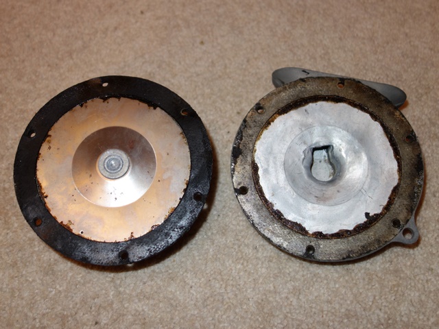
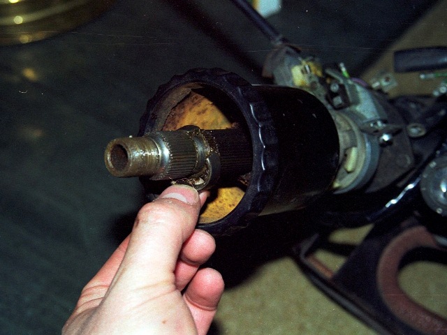
The rivets were drilled and then punched out – the rivet inside the trumpet is slightly shorter than the others so I’ll have to remember that when ordering fixings to hold it back together. The two halves can then be carefully separated as the diaphragm was sandwiched between two thin, wax impregnated gaskets which are quite fragile.

Drilling out the rivets Horn carefully split in two Metal diaphragm removed

The rivets had to be drilled and then punched out to split the horn

The horn split in two - the right hand side has no moving parts and is just the horn snail or trumpet

The diaphragm removed, showing its ferrous attachment and disc operating to operate the contact points

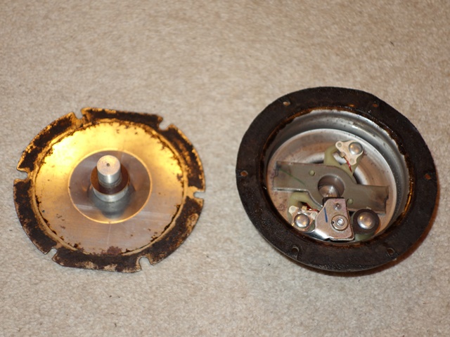
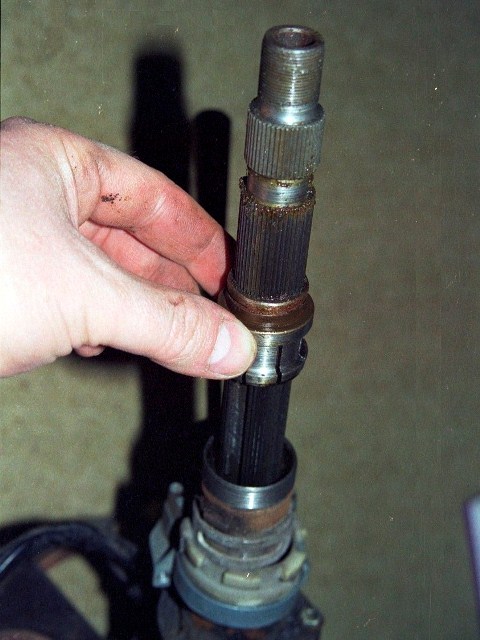
The diaphragm was then removed to reveal the inner workings. Attached to the centre of the diaphragm is a ferrous cylinder so that its movement can be controlled by the rapid switching on and off of an electromagnet.

When current is applied, the ferrous cylinder and therefore the diaphragm is drawn towards the electromagnet. As the diaphragm nears the end of its travel, a disc around the ferrous cylinder hits the base plate of the contact breaker, opening the points. The electromagnetic field then collapses and the diaphragm returns to its natural position and the process is repeated.

Operating the base plate of the contact breaker to open the point. The points were cleaned with some 400 grit wet and dry paper
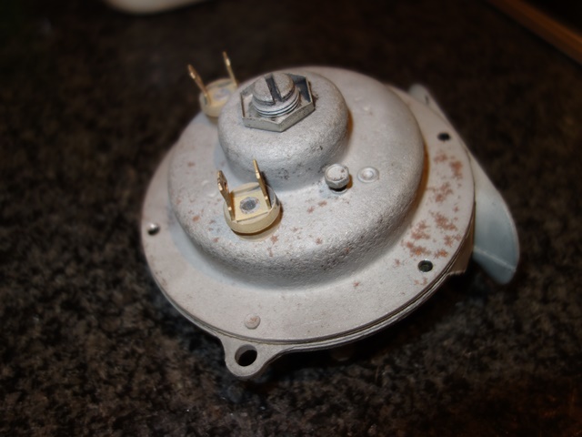
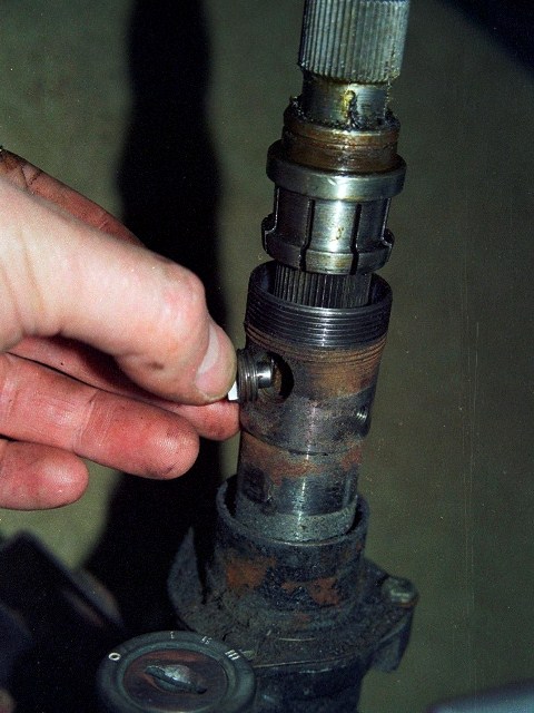
The resistance of the contact points was around 7 ohms so a light rubbing with 400 grit wet and dry soon got this down to 0.8. Although I wouldn’t have thought this would stop the horn operating. I think the problem is with an external screw fitting which the service manual suggests should not be touched.

I’m fairly sure it has been adjusted at some stage as it’s screwed tight against the ferrous attachment. Therefore stopping any possible movement in the diaphragm.

Of the two external adjustments, the small screw adjusts the contact points gaps. The service manual states that this does not adjust the tone and is only to take up wear in the points. The central screw adjustment, with locking nut, only limits the length of travel permitted by the diaphragm so if it did effect the tone it would only be marginal (ie for fine tuning). I doubt it would give anywhere near the variation to recalibrate it to the low-tone.

Hmmmm …. stumped. Going back to first principles, due to the lack of tone adjustment in the electric components. The tone must be controlled mechanically but the spring rate of the diaphragm is fixed. Therefore the only two things that I can see that would effect the output tone are the mass of the ferrous diaphragm attachment, which would naturally impact the switching frequency, and the shape of the trumpet.

Neither of these two can be changed (easily) with the parts I have in front of me! I’ve found a restorer of old horns, Taff The Horns, who might have a non-working low-tone horn to provide a donor for a transplant. Otherwise plan B is to purchase a repro horn from Holdens for about £40!

A whole post on horns without a reference to a sketch by the late Peter Cook!!

 Posted by at 8:02 pm  Tagged with:
Oct 152013
 

One of the safety features introduced during the production of S1 4.2 cars and carried over to the S2 was a collapsible steering column. The lower section of the steering column housing consists of a lattice structure. In the event of an accident where the steering wheel is impacted with sufficient force, the column’s two upper mounting points are designed to shear and the lattice structure collapse to absorb some of the impact and allow the steering wheel to travel forward.

To enable the column to collaspe, the total length of the inner steering shaft must also be allowed to shorten. To achieve this, the inner shaft is comprised of two sections which are fixed in position by two nylon pins. An impact will cause the pins to shear, allowing the two halves to slide over each other.

The same design is used for the lower steering shaft, connecting the steering wheel column to the rack. Therefore some care needs to be taken when handling and refitting the steering shaft to avoid any heavy impacts and the use of mallets to fully engage the splines!

The steering wheel’s fore and aft position can be adjusted by rotating the large black cup-shaped locking nut to release the clamping pressure on a split collet, thus allowing splined inner columns to slide over each other.

Another difference between the early S1 and later cars was that the horn was now activated by pressing the indicator stalk rather than the E-Type motif in the centre of the steering wheel. I assume this might have been partly due to having to make the steering column collapsible but it does simplify the dismantling.

The E-Type motif is normally held in place by three grub screws in the aluminium steering wheel boss but for some reason a previous owner had also glued it in place! It’s removal provides access to the nut clamping the boss against a split cone located in a recess in the inner shaft.

A split cone is located in a recess in the inner shaft. The central nut clamps the steering wheel boss against the cone.I was surprising how much force was needed to loosen the nut. It was necessary put on full lock and then use an extension tube over the socket wrench handle to get enough leverage.

It’s just as well I didn’t take it off the car as a complete unit as it would have been a struggle without having the resistance of the steering rack at full lock.

As mentioned, the adjustability in the steering wheel position is achieved by two splined inner columns being able to slide over each other. Their travel is limited by a ‘stop button’ which is screwed through the female inner column and locates in a machined slot in the male inner column.

The steering wheel is then locked in place by a splined split collet, which is attached to the underside of the cup-shaped lock nut by a circlip. When there is no clamping force, the male column is free to move on the splines. However, by screwing the lock nut onto the female column, the collet is compressed and clamps the two inner shafts together.

Once the circlip is removed, the lock nut can be unscrewed and withdrawn, followed by the collet. Next is the stop button to allow the male inner column to be removed.

The black cup shape lock nut can be withdrawn once the circlip is removed The split collet can then be removed by sliding it over the inner column splines The stop button which limits the travel of the male inner column within the female column.

The female inner column passes through the indicator mechanism, attached to the main steering column housing by a semi-circular bracket. Automatic indicator cancelling is built into the mechanism by the use of a control striker attached to the inner column.

Removal of the semi-circular bracket securing the indicator mechanism to the steer column housing The indicator control striker is secured by two set of screws and curved washers/spacers

The striker interlocks within a white nylon ring in the indicator mechanism so that the ring rotates as the steering wheel is rotated. Protrusions moulded into the nylon ring hit ‘cancelling’ cams which force the indicator stalk back to its non-indicating state when the steering wheel returns towards the straight ahead position.

All that remained was to liberate the female inner column from the steering column housing. The inner column rotates in roller bearings at each end. The lower bearing is held in place by a retaining cover which itself is secured by a circlip and a number of washers. One of which is a wave or spring washer which takes up any free play and provides a small amount of load bearing capacity.

Once the cover and washers are removed, the splined inner bearing race can be slid off the inner steering column and the roller bearing withdrawn. The outer bearing race is simply a press fit into the steering column housing.

The lower bearing and a series of washers are secured in place by circlip Removal of the inner bearing race and roller bearing

The steering column housing’s upper end cover can be removed by releasing the three small retaining bolts.

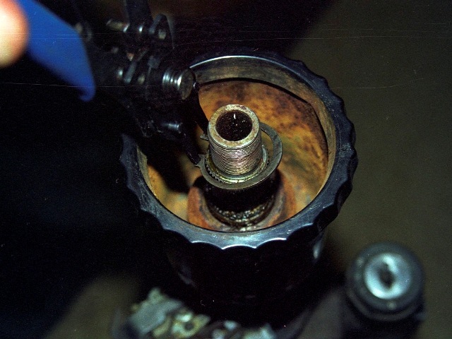
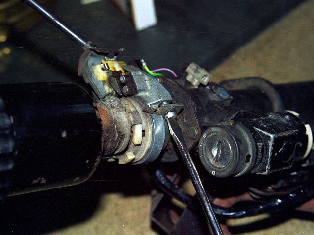
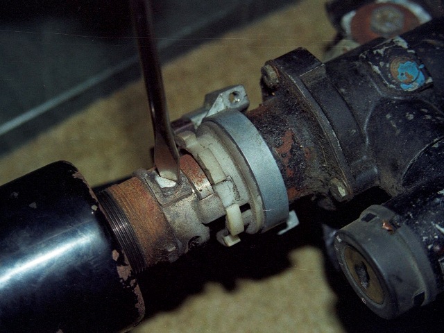
At which point the key needs to be turned in the ignition to withdraw the steering lock. This enables the female inner column to be removed.

The ignition switch and steering lock housing is secured to the main housing by a security bolt, which needs to be drilled out in order to remove the lock. The security bolts are designed so the hexagonal part used to tighten the bolt shears, removing the ability to remove it easily.

It’s worth noting that it would be possible to remove the whole inner column as a single unit, even keeping the steering wheel in place, by:

  • Removing the lower roller bearing circlip and withdrawing the washers, cover and inner race
  • Undoing the three bolts securing the steering housing’s upper cover
  • Turning the key in the ignition and withdrawing the entire inner column

This would enable the roller bearings to be replaced without resorting to dismantling the entire steering column.

Sep 202013
 

There wasn’t time to investigate why the bonnet wouldn’t shut the last few inches, so I had a chance to sleep on it. The problem was that it’s not possible to see inside the bonnet area at the point its travel begins to be obstructed.

Only the engine and radiator has been installed so it shouldn’t be too difficult to work out. I remember reading somewhere on the E-Type forum that the Series 2 had an extra spacer somewhere in the engine mountings. Although I thought this only affected the carburettor clearance but these were still to be fitted.

Some off-cuts of the foam rubber Dynaliner were place strategically on all the high points. I was aiming to lower the bonnet to the obstruction and then inspect the Dynaliner. The foam would take a little while to return to its previous state so the indentations of any impact would remain and be easily traced.

The radiator support struts had been fitted at a jaunty angle so this was almost certainly the cause of the problem .... or was it?A couple of attempts still didn’t reveal an area of compression in the rubber …. more head scratching. It was definitely not the engine as this was almost entirely encased in Dynaliner.

It finally dawned on me – it must be the radiator support struts impacting the vertical sides of the air intake channels. When they were first installed, it was mentioned whether they should be fitted on the inner or outer side of the damping rubber grommet.

With hindsight, they did look angled when mounted on the outer sides. The brackets were removed and the bonnet was lowered to prove the theory. Spot on …. the bonnet reached the landing rubber without being obstructed.

The struts were reinstalled but this time on the inboard side of their grommet. The bonnet was lowered, having finished the job, only the problem was still happening!

I thought I'd found the issue had been caused by the radiator struts. Re-fitting them differently resulted in a gouge in the paint workHowever this time, when the bonnet was raised to investigate, it revealed a 4-5 inch scrape in the paint on the air intake duct. Gutted.

The strut positioning was only part of the problem. They were causing the ‘springiness’ of the impact because the bonnet edge was hitting the strut and just pushing it aside.

Once it had be repositioned and was out of the way, it allowed the bolt head, securing the strut to the radiator, to take a gouge out of the paint work.

The bolt head was sitting too proud because I’d used a washer between the radiator and the strut and one between the strut and the bolt head. Without them, it would probably have been ok. However I’m going to remove all the washers, fit a thin-headed bolt and reposition the radiator on the bottom mountings to try to centralise it with the bonnet.

 Posted by at 8:59 pm
Sep 192013
 

It has only been just under a month since the rear suspension was put in, in which time the weather has started to turn, with leaves falling and a persistent dampness on the ground. The hope was to recruit John and Martin again to put the engine back in and set up the front suspension. However doubts started to creep in whether a leave of absence would be forthcoming from their higher authorities.

Still we pencilled in the last weekend in September for the engine install just in case permission was granted! It was the last free weekend before the clocks change but the problem would be if the weather wasn’t favourable on the day. The next available weekend would not be until early December.

I decided it might be better to go it alone earlier, on the next fine day, but keeping the September weekend as a reserve. So the BBC weather forecasts were monitored for a suitable, sunny day. A whole day with only light cloud cover and sunny spells was forecast, so last minute arrangements were made to have a days leave to finally install the engine and front suspension.

The original plan was to remove the front ‘picture frame’ and simply wheel the engine into place and then refit the frame behind it. I should know by now that nothing is ‘simple’ when rebuilding an E-Type! As the rear suspension had taken all day and we’d run out of time, the revised plan was to install the engine from below. The same way it had been removed.

At least this time, the engine was on a low trolley so the front of car wouldn’t have to be raised quite as much to gain the necessary clearance. The positioning of the engine within the frames went without a hitch and the trolley castors made fine adjustments in its position a breeze.

Although there was almost a numpty moment as the engine was being rolled into position – it generally helps to have the propshaft fitted before the engine goes in!!

The car was then lowered until the front fulcrum mounts could be supported on axle stands, enabling the lifting frame to be moved and redeployed to lift the engine on to its mounts. The clearances around the bellhousing are quite small, especially round the torsion bar mounting points, so the lowering progressed very slowly to ensure the paintwork wasn’t damaged.

Lifting the engine was an equally slow process for the same reason. It was also very marginal whether the lifting frame would have sufficient height due to generous length of the lift strop. Fortunately there was, but only by a centimetre. It would have been possible to shorten it by putting a knot in but I suspect it wouldn’t have come undone once the full weight of the engine had pulled it tight.

The gearbox mounting bracket and damping spring, which sits in two rubber mouldingsI had wrongly assumed that once the mounting brackets had been fitted to the engine, the weight would naturally align their bolt holes with the engine mounts fixed to the frames. After a considerable struggle, not dissimilar to the fitting of the rear suspension, everything was lined up and the front engine mounts could be secured.

A strong spring sits between the gearbox and the rear mounting bracket to dampen the vibrations of the engine. Fortunately is was only a matter of jacking up the bracket to compress the spring sufficiently to get the bolts in place. Although some care was taken to make sure the spring was located centrally on the trolley jack.

There’s very little room to get in to fix the engine stabiliser so it’s a fiddly job
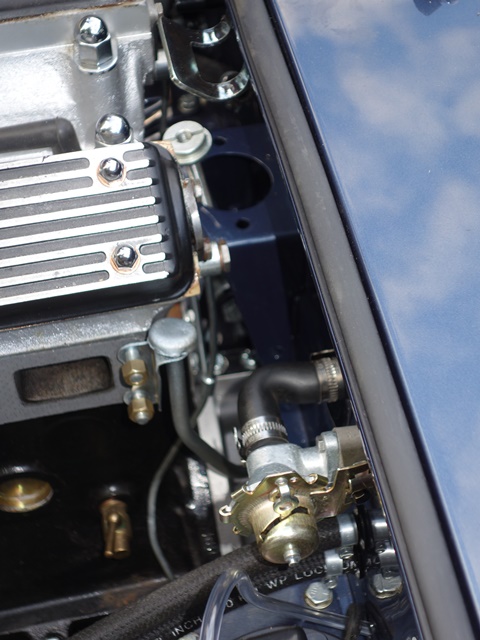
I thought it would be easier to fit the central engine stabiliser once the engine was in place, as it’s one thing less to keep an eye on when the engine is lifted. It’s was fiddly job as there’s very little room between the engine and the bulkhead to get your fingers in. I think I’d prefit it next time.

Once again the progress was considerably slower than hoped although this was partly due to the accuracy of BBC weather forecasting – light drizzle and grey skies were the order of the day. As dusk approached, the installation of the torsion bars was abandoned for now.

The radiator and cooling fans had already been built up so these were quickly bolted on before the bonnet was refitted. It was time to wheel it inside and head off to the pub for a celebratory meal …. so it wasn’t the best time to find out that the bonnet no longer closed. Something was stopping it about 2 inches short of the landing rubber.

It wasn’t a solid contact you’d get between two hard objects. It was more springy. Some of the wiring looms still had to be re-routed so these were moved well out of the way. Still no joy. The problem is that is almost impossible to see into the engine space when the bonnet is almost full closed.

It can only be one of two things as the engine and radiator were the only items fitted but at the moment I’m stumped. Some padding has been inserted between the bonnet and bulkhead until I can it work out!!

Sep 162013
 

The heater valve was another part that was difficult to remove, as the bulkhead heater pipe had seized solid into the valve body. I didn’t want to apply heat in case it damaged any internal rubber seals and so I tried to break the joint by rotating the valve body. All this achieved was to deform the pipe, which eventually had to be cut to remove the valve.

There were signs of weeping from the valve so I suspected an internal seal had started to deteriorate and it would need replacing. The valve consists of a pot metal valve body and a plated end cap. The body has protrusions around its circumference which interlock with corresponding hook shaped protrusions on the end cap and then a single rivet stops the end cap rotating relative to the valve body.

The rivet was drilled out and then it was fairly easy to split the valve in two by rotating the end cap. This revealed the cause of the weeping – a sprung rubber diaphragm, that is used to control the passage of water, had become furred up.

The deposits had compressed the rubber seal in several places so it no longer made a complete seal. The rubber had also hardened over time so wouldn’t spring back fully once the deposits had been removed.

Even after extensive internet searches, I haven’t been able to find a supplier that just supplies the internal rubber diaphragm. Unfortunately the options are very limited.

Either purchase a complete repro valve or a repair kit from an American site, which includes everything but the valve body. However the kit was considerably more expensive than the repro valve, so I went for the latter.

Overall the quality of the new valve was fine, only let down by the finish of the valve body casting. It wouldn’t make any difference to the operation of the valve but I would have preferred to keep the original body.

Sep 142013
 

The lock barrels are of the wafer tumbler design where five sprung loaded wafers protrude at the top of the barrel. They align with corresponding slots in the handle’s push button and stop the barrel from being rotated inside the push button.

A retaining pin then stops the barrel from being withdrawn from the push button.

The profile of the matching key is such that, when it’s inserted, it draws the wafers inwards until they are all flush with the barrel’s circumference. The barrel is therefore able to rotate unhindered within the push button.

Another feature of this design is that it is not possible to remove the key when the wafers and slots in the push button are not aligned. The wafers need to be allowed to protrude in order to release the key. In effect, they are clamping the key within the lock.

The return spring fitted to the lock barrel ensures the lock always returns to the position allowing the key to be removed 
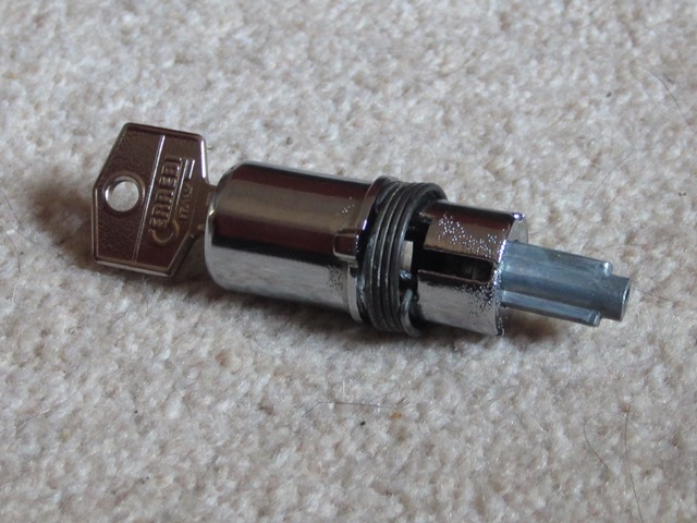
A spring is fitted to the inner end of the lock barrel which ensures it always returns to the aligned position, allowing the key to be removed.

Slotted on to the rear of the lock barrel is a profiled plunger which has two ‘ears’ at its base. The plunger is not attached to the barrel but its movement of travel, both rotationally and in/out, is limited by the shape of the rear of the lock barrel.

The plunger serves two purposes; the operation of both the door latch locking mechanism and the door latch release lever.

Operation of the Latch Locking Mechanism
The rear of the lock consists of a spring between two washers, the lock operating lever, lock end housing and plunger fixing screw. The operating lever and housing both have a hole matching the profile of the plunger.

The fixing screw ensures that the ears of the plunger are positioned in line with the end section of the lock barrel (when the button is not pressed).

In doing so the plunger is always engaged in the hole in the lock operating lever.

When the key turns the lock barrel, the plunger ears will come into contact with the edges of the lock barrel. At this point the plunger and operating lever will also turn.

The installed door lock with the latch release lever immediately behind and the sprung linkage to the latch locking lever
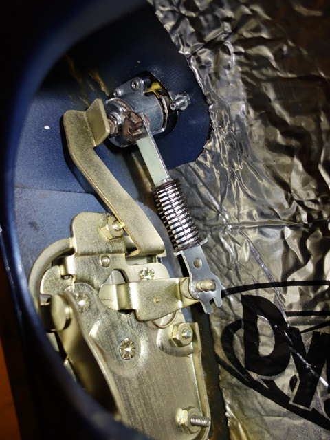
A sprung linkage is attached between the operating lever and the locking lever of the latch mechanism, mounted below on the rear face of the door. Therefore the latch lever will either be pulled (unlocking) or pushed (locking), depending on the direction of rotation of the key.

The purpose of the spring is to provide some resistance in the rotation of the operating lever and engaged plunger. As a result, when the key is turned to lock the door, the operating lever and plunger will remain in the locked state when the key is released which affects the operation of the latch release lever, describe below.

Operation of the Door Latch Release Lever
The hole in the lock end housing allows the plunger to pass through when it is correctly aligned, which is when the door is unlocked. At which point, the plunger ears will be engaged with cut outs in the end of the barrel. Pressing the button will push the barrel inwards and with it the plunger. The plunger passes through the housing until it hits the latch release lever allowing the door to be opened.

In the locked state, the plunger ears are aligned with slots running the length of the rear part of the lock barrel. This time, when the button is pressed and the lock barrel moves inward, it simply slides past the plunger and the release lever is not activated.

Rebuilding the locks
The first issue was only one key was provided which only operated the drivers door and not the passenger door or glove box. So the both door locks must have been changed at some point in time. I could live with having a separate key for the glove box but it would become annoying for the doors.

Unfortunately replacement sets of matching lock barrels haven’t been available for a number of years. After quite a bit of searching I found a classic car lock specialist who could replace the wafers to produce a pair of matching barrels. A couple of days after sending them, a match pair were returned.

By chance, a month or so later, a friend contacted me asking about replacement locks on behalf their friend who has an E-Type out in Harare (their car was first registered in Zimbabwe on 6 January 1970, only 5 days after mine was registered!). I mentioned they’d been unavailable for some time and the hassle I’d had with the locks. When he made some enquiries with SNG Barret, complete barrel sets including the boot and glove box were available and had just come back in stock, for little more than I paid to get mine matched – another case of poor timing on my front!!

With the lock internals removed, the handles and push buttons were sent away for re-chroming. Overall I was pleased with chroming work, except for the handle and push buttons as the plating process had deposited too much material (I think this is quite a common problem). This stopped the buttons from moving once inserted into the handles and also stopped the barrels from being inserted into the buttons.

They were sent back but even when the returned the fit wasn’t good so I carefully removed some material from the inside of the handle with a Dremel. Not only that but I’d accidentally left one of the retaining pins in the button for safe keeping. It was then firmly re-chromed in situ and was not that easy to drift out. I can hardly complain about that as it was my fault!

Stoneleigh is a great place for picking up obscure parts such as a new lock housingOther immediate issues were one of the alloy lock housings had broken around one of its mounting holes and the inner washer, inserted before the large spring, was missing.

To my surprise I found a stall at the Jaguar Spares Day at Stoneleigh that were selling reproduced alloy housings so that issue was easily resolved. As yet I’ve not sourced a replacement washer which I have subsequently found out causes a problem.

The operation of both locks had started to suffered due to a build up of dirt and greaseBoth locks had become clarted up with dirt and grease over the years. One so much so that it was difficult to rotate the key.

I think the problem is that grease and heavier oils tend to pick up more dirt. I’ve used Lock-Ease graphited lock fluid when putting the locks back together which will hopefully reduce the build up in future. It’s also designed to reduce wear and keep them working in freezing temperatures.

I rebuilt a lock without replacing the missing washer to see if it was absolutely necessary. The lock worked fine which was good news …. until I’d operated it half a dozen times and it began to seize up. The washer sits between the two springs within the lock. Without it the springs start to entangle. I now suspect this was why one of the locks was harder to turn rather than just a build up of grime.

I’m a bit stumped on how to resolve the issue as I’ve not been able to find a replacement yet …..

Sep 122013
 

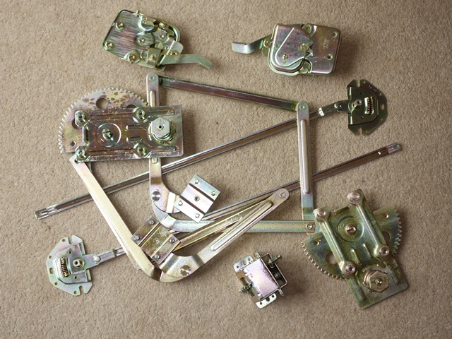
The window regulators and door latches had come back from the platers looking almost like new. The interior space within the door will be subject to a lot more moisture than most of the other areas of the car, so these were given a coating of Dinitrol hard wax.

It seemed a good time to tackle the drop glass while the wax dried overnight. A job I’d been putting off since attempting a trial fitting.

The drop glass is retained in the glass support channel by a thin strip of rubber. Unfortunately both channels had suffered from quite bad corrosion.

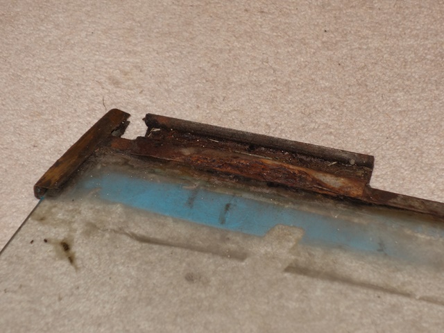
The first was so weakened that it bent when the glass was removed. Fortunately replacements are available but as usual they’re a long way off the quality of the originals.

The trailing edge slides within a channel in the window frame and was originally made out of brass. The repro items are just folded steel.

I was half tempted to try to replace the trailing edges by cutting off the steel and brazing on the old brass sections. On further inspection it wouldn’t be that easy to achieve and I’d probably do more harm than good.

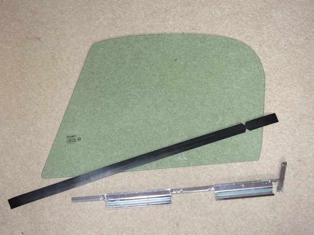
The first trial was to place the rubber in the channel and then trying to insert the glass. As there wasn’t any lubrication, this mainly compressed the rubber into the channel. The rubber had more of a tendency to push the glass out of the channel than hold it in place.

The problem with the second trail, trying to place the rubber along the length of the glass and then pushing both into the channel, was that it was very difficult to keep the rubber evenly spaced all the way along. Not that it would really matter as, hopefully, it won’t be seen for quite some time after the car is finished!

In the end I used strips of duct tape to temporarily hold it in place. The tape was only needed until the full length of the glass was just in the channel. At which point the rubber is compressed sufficiently around the glass so it can’t move. The tape could then be removed before it became trapped between the rubber and the channel frame.

A short length of rubber strip is also needed up the trailing edge of the support channel so two wedges were cut out to stop the rubber ruffling up where it rounded the corner. The rubber was given a liberal covering of slightly diluted Fairy washing-up liquid before the support channel was knocked into place with some sturdy taps with a nylon hammer. It was easiest to get the trailing edge tapped home before working the way along the length of the channel.

In the end it was a lot easier than I thought it might have been. The window regulator runs in the two channels at the base of the support channel. A stop is used to limit this movement thereby setting maximum height that the window can be raised. Unfortunately the stops were missing so I will have to fabricate some later.

Sep 122013
 

Quite early on the radiator had been sent off to Northampton Autorads to be ‘re-cored’. It was then stored for a number of years as progress with the restoration ground to a halt. Partly due to lack of time but also a lack of enthusiasm once it became clear how much work was involved in a full restoration.

It was only once the rebuild had restarted in earnest that the cooling fans and shroud were refurbished. Both, in different ways, had been a trial in perseverance to get the desired finish. So it was a real disappointment to find out all the mounting holes down each side of the radiator were too far from the edge to enable the shroud to fit.

There was no way I was going to hack the shroud to fit after the palaver to get the correct crinkle finish. Northampton Autorads usually have a stand at the Stoneleigh spares day, so I took it up on the off chance that they might be able to have a look at it and suggest the best way to modify it.

To my amazement they agreed it was wrong and simply replaced it on the spot, despite the considerable time since it was manufactured. I was quite willing to pay for the modifications as I should have reported any issues when it was first returned. I was impressed with their customer service!

Generally you learn from your mistakes, however I wrapped up the radiator on my return and set about tackling the ever growing list of rebuild tasks. It was some nine months later that I started to prepare for the big installation weekend, transforming it from a bodyshell to a rolling chassis, when I again tried to reunite the radiator and shroud.

I couldn’t believe it – the mounting holes were again out of alignment. Neither the shroud nor the radiator mounting brackets could be fitted. I sheepishly emailed them with the pictures below and they immediately arranged to collect the radiator by courier. This time the shroud and brackets were included so they could ensure it all fitted.

Only two shroud mounting holes aligned Radiator mounting bracket holes were also wrong
The lower mounting hole for the shroud didn't align. The problem is that this hole is also shared with the radiator mounting bracket The radiator mounting bracket holes were only marginally out but enough to stop the brackets being attached

Less than a week later, everything was returned all made up. I really can’t fault their customer service as they addressed the issues without question. I’m not sure why the manufacturing process is such that positioning of the mounting holes is so prone to error. I think nowadays, when a radiator is re-cored, all but the top and bottom sections are replaced so the original sides are thrown away.

At least the unit is now ready to be fitted when the engine goes in ….

The radiator, shroud and cooling fans all ready to go on as a single unit

Handbrake puzzle – one step forward, two back

 Brakes  Comments Off on Handbrake puzzle – one step forward, two back
Sep 072013
 

The missing handbrake parts for the warning light switch were ordered from SNG Barratt – the bracket, switch and ‘S’ shaped spring. It looked fairly obvious how it should all go together but what puzzled me was the parts list indicated only two nuts are required to secure both the switch and spring to the bracket.

The switch is actuated by a finger-like protrusion at the base of the handbrake arm, which should press against the spring as the handbrake is nearing the fully released position. This causes the spring to depress the switch’s plunger, breaking the circuit and so switching the warning light off.

The handbrake warning light switch set up - something's wrong but I couldn't work it out
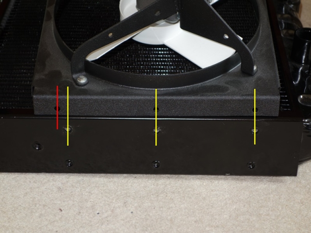
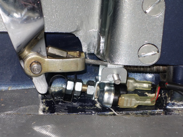
The only way I could get the switch’s plunger anywhere near to the ‘finger’ protrusion was to mount the switch to the bracket and then use two locking nuts to position the spring at the end of the switch – as shown in the photo.

I’ll be swapping to half nuts to secure the spring but pressing the spring just about operates the switch. However the problem is the ‘finger’ protrusion of the handbrake only just brushes the spring and doesn’t push it against the switch.

I posted the photo on the E-Type forum and within no time at all the moderator, Angus, had responded, directing me to an image of the correct set-up on a S2 car currently going through his workshop, Moss Jagaur.

I went backwards and forwards between the two set-ups but still couldn’t see how mine was so far out. After all, the geometry is fixed. Eventually I noticed the length of my cable fork was much longer and then it dawned on me what was wrong.

The correct position for the switch mounting pointMy handbrake had been hacked about at some time in the past. The bracket attachment has been cut off and welded further back.

There had been some obvious welding around the attachment point but I had assumed this was just a repair to strengthen it and, as it has come off the car, was correct. It now explains why they hadn’t refitted all the switch parts!

The annoying thing is all the parts have been re-plated and the ratchet teeth are all in good condition. I think I’m going to keep it ‘as is’ and adapt the bracket, although it’ll bug me now!

Further responses to my forum post pointed out that the handbrake cable is an incorrect reproduction item, which would explain why the clevis fork is longer but more importantly that they cables are too long to get the handbrake to work correctly.

The repro cables have been on sale for many years, and still are!, and it points to a previous owner having gone the wrong way trying to find a solution to the problem. The repro cable problem had been picked up by Jaguar Enthusiast Club, who now offer the correct cable so one is now on order.

It’s cases like this where the E-Type forum is invaluable. There are members with a wealth of knowledge of these cars who are happy to spend time offering others advice and solutions to their problems.

Repairing the plenum chamber

 Air Filter  Comments Off on Repairing the plenum chamber
Sep 062013
 

Ropey would be an understatement when describing the plenum chamber. It appears that it was manufactured by bonding two halves together as, once the superficial layers of dirt were removed, cracks were found along the joining lip between the top and bottom halves.

Also, for some unknown reason, a previous owner had drilled a 3/4″ hole in the underside and, looking at it, presumably while blindfolded.

The first thing to do was to remove all the grime and paint in order to make repairs. I was a little bit apprehensive about using strong paint strippers such as Nitromors as I’d heard it damaged fibreglass. Then someone recommended using Fairy Power Spray – I think it’s one of their oven cleaning liquids!

I must admit I was rather sceptical to sat the least. Still, the oven needed cleaning, so if it didn’t work, it wouldn’t be wasted! To my amazement it acted as a very mild paint stripper. Whereas the paint starts to bubble up within a second or two with Nitromors, the Fairy stuff took 5-10 minutes and needed 5-6 applications to remove all the paint.

I guess it shouldn’t have been too much of a surprise as it is designed to cut through oil and grease. The original paint would have been oil based and presumably traces of oil are retained even once the paint has dried.

The air intake brackets were drilled out to provide better access for the repairs or, probably more truthfully, a case of shipwright’s disease. At some stage the brackets must have been painted silver as underneath and in areas that were not visible they were painted black.

I decided to make a fibreglass repair rather than just use filler. The main reason was an attempt to strengthen the join where the two halves had started to come apart, at each side of the opening. The repair sections were built up with three layers of fibreglass which should be sufficient. The mystery hole was also covered over at the same time.

It was then just a case of filling all the various cracks, chips and the repaired hole with Isopon filler before spraying the plenum and air intake bracket with numerous coats of silver Hammerite.

One thing I’ve found with Hammerite paint from painting the wiper motor housing, is that it takes many months to fully harden. Even though it’s dry enough to handle, it’s still quite easy to damage the soft finish for quite some time. Overall I was quite pleased with the end result.