The exhaust system is another area where there are a plethora of options available and with them, opinions on which is best. These range from a standard bore with cast manifolds through to straight through, big bore pipes with either long or short tubular manifolds and all combinations in between. Advice often just reflected what the owner had decided to put on their car rather than comparative tests.
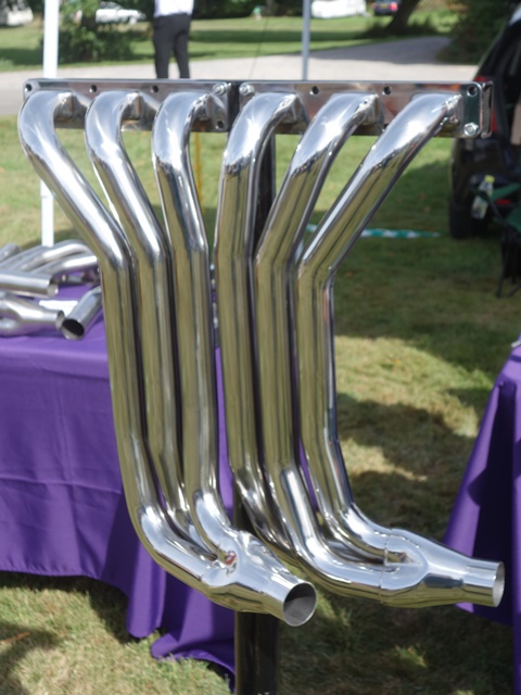 It was tempting to go for one of the tubular manifold systems from companies like Classic Fabs, which are a work of art.
However the administrator of the E-Type forum had done a fair amount of research backed up by practical experience, having fitted most of the different types available.
The general consensus from the forum discussion was that the original cast iron manifolds were very well designed; providing optimised gas flow to speed up the exhaust gases therefore improving low down torque but also heat management. The larger bore systems, specifically when used for the secondary pipes, can result in a torque dip lower down in the rev range.
The other issues are that they are more prone to grounding and tubular manifolds generally radiate far more heat which is then likely to cause other problems, such as brake issues due to the proximity of the brake servo and blistering of the paint work.
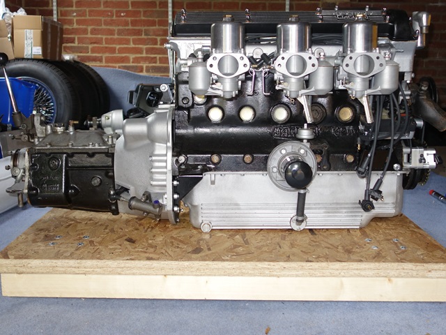
 It therefore seemed sensible to stick to the standard cast iron manifolds and 1.75″ bore system, which was purchased from PD Gough based in Nottingham.
I’d also decided to deviate from the original look at the rear after seeing others who had successfully avoided the slab-like appearance by removing the rear, brushed aluminium panel. The car will be fitted with a long rather than square number plate which enables straight exhaust resonators to be fitted instead of the standard S2 splayed ones.
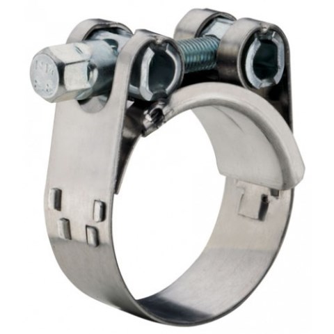
The final decision to make was whether to have the system made in mild steel or stainless steel. Apparently mild steel gives a much nicer exhaust note but in the end I went for stainless for longevity. Another recommendation that I also adopted was to fit Mikalor style clamps as they apply the clamping force more evenly and avoid distorting the pipe joints.
Some ‘reject’ manifolds were picked up quite cheaply at the SNG Barratt open day – they had some tiny imperfections in the vitreous enamel finish which I still struggle to find. This finish was never very robust and had a tendency to crack and flake off. So I’m expecting it won’t last too long and will need to be removed in order to paint/treat the manifolds.
The engine installation weekend was fast approaching so I decided to trial fit the exhaust system. At this stage, without the engine in place, all that could be trial fitted was from the muffler section backwards.
 The combination of not having the down pipes installed and the car being on axle trolleys meant it was extremely difficult to build the exhaust on the car. The pipe ends were unblemished so the system clearly hadn’t be bench fitted when it was manufactured. Therefore all the joints were still very tight even with a generous coating of Copperslip.
It was necessary to build the system off the car to have any chance of aligning the brackets on the intermediate pipes and to push the resonator pipes fully home to be able to mount them onto the rear hanger.
It was then fitted as a single unit, first fitting the muffler section to the four rubber mounts fixed along the chassis rails. I was struggling underneath the car trying to hold up the exhaust up to the mounts while feeling for the 1/2″ spanner that I’d dropped when I noticed I had an audience – a metre long grass snake was observing my progress a couple of feet away. I assume having taken refuge from the hot, sunny weather.
| Mounted centre muffler section |
My new helper! |
Resonator pipes mounted at rear |
 |
 |
 |
The connecting brackets between the intermediate pipes and the resonators were all fixed so the whole exhaust was now quite rigid. The muffler section was already mounted but the resonators needed a reasonable amount of effort to push them up to reach the rear exhaust hanger. In doing so, it caused the muffler section to raise significantly at the rear so the output pipes hit the rear floor stiffener.
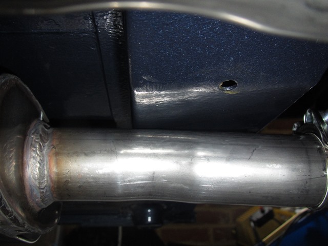 It didn’t seem right because the small rubber mount at the rear would be under considerably more stress than just supporting the exhaust’s weight. Apart from varying how much overlap there is in each joint, there is no other scope for adjustment and the geometry is fixed so, without modification, the pipes would almost certainly foul the rear floor stiffener.
I emailed PD Gough with the photos above explaining the issues I was having and the purpose of the trial fit was to ensure it fitted correctly before the engine installation weekend. I didn’t want to find out it didn’t fit during the installation weekend and therefore stop the testing of the engine.
I felt their response was more of a fob off and so wasn’t too impressed – “they’d never had any fitting issues before and would be surprised if I had fitting problems once the front pipe are fitted as they would generally bring the system into alignment”.
Personally I’m not convinced because the front pipes are flexible and so their ability to bring the whole exhaust into alignment would be limited. Also the forcing of the muffler section towards the horizontal to stop the clearance issue will only add to the stress on the rear rubber mount.
I’m going to be extremely annoyed if I end up having to ‘surprise’ them by informing them it doesn’t fit.

 The issues getting the rear suspension fitted meant that there wasn’t time to fit the front suspension let alone the engine.
  The original camber shims had been re-plated and were fitted behind the front and rear mounts. I suspect the shimming will need to be changed when the geometry is finally set up because the new engine frames have been fitted.
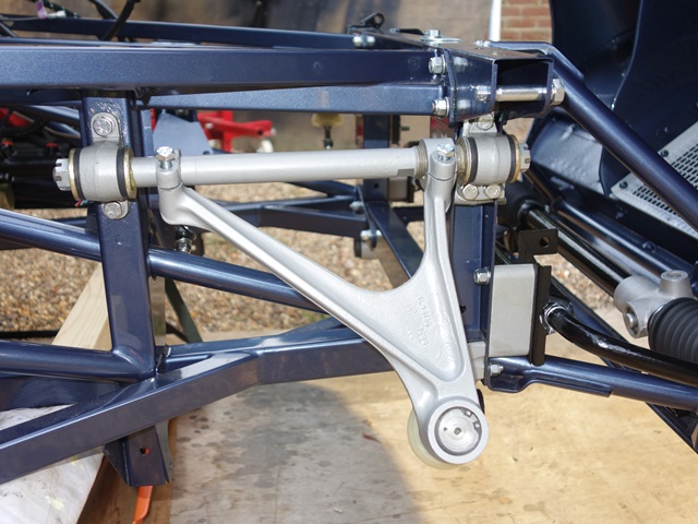


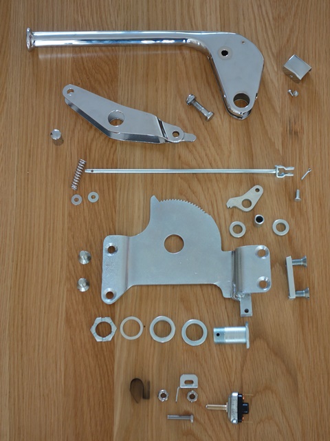 The handbrake had been sent off to ACF Howells for re-chroming as a complete unit. With hindsight it would probably have been better to dismantle it myself and just send them the pieces that needed re-chroming.


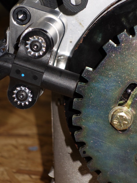
 Next the ratchet gear needs to be inserted into base of the handbrake arm followed by fitting the outer cable attachment bracket. Similar to the pawl, the ratchet gear uses two spacers to fill the internal space within the handbrake arm.
  The final piece in the puzzle was the fitting of the handbrake warning light switch. As mentioned, these parts were missing and so replacement parts were ordered from SNG Barratt.


 Not many companies do Zinc-Nickel plating and generally don’t take private work from individuals. Fortunately I was able to arrange for my parts to be Zinc-Nickel plated as a favour. However, without asking for it, they had yellow passivated them so they had an ‘oil slick’ appearance which I think would have looked awful on the car.


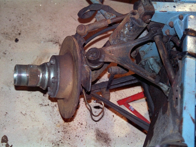
 There wasn’t too much wrong with the steering rack, apart from some splits in the ball joint rubbers and bellows, which could be expected for the age of the car. Externally it looked a bit tatty but there didn’t appear to be any significant wear in the rack and pinion. There was only some very minor pitting in a couple of the rack’s teeth.


 With time running out, I had little option but to bite the bullet and purchase a new rack and pinion from Kiley-Clinton engineering. I knew I’d probably find the original rack shortly afterwards but the knock on affect of replacement would also be a full rebuild of the steering unit.
 The removal of the brass bush proved rather tricky without access to proper presses. As it’s fairly thin walled it’s difficult to get a drift on to it and I had to resort to a cold chisel to get it out.

 Just as all the components were ready to be rebuilt, I was searching for the gearbox breather when I stumbled upon the long lost original rack. Aaaargh!
 The pump raced when it wasn’t under load. So far, so good! However when the inlet pipe was placed in the bucket of paraffin it didn’t quite go as planned. It stopped immediately! I tried retuning the electric circuitry by repositioning the Hall Effect fork through its full arc of travel but it still refused to pump. It was a bit gutting having spent all that time and effort.
 The proof would be in the achieved flow rate which, over three tests, averaged out at 1.6 litres or 2.8 pints. Phew!
 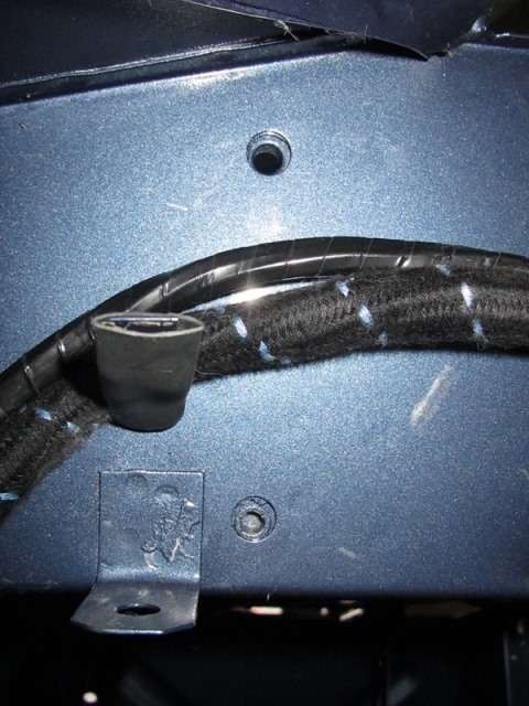 The Megajolt control unit is fitted to the bulkhead just behind the glove box. Rather fortuitously the mounting points for the steering column is exactly the correct spacing for the Megajolt unit, so the unused LHD column bolt holes are used to secure the unit to the bulkhead.


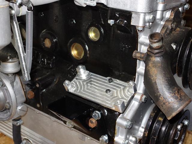


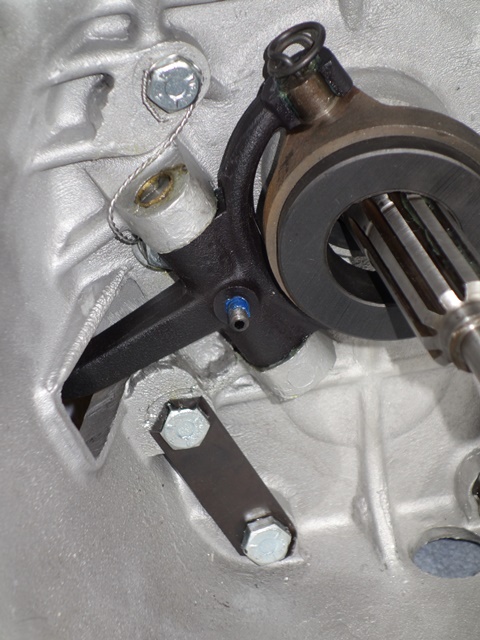
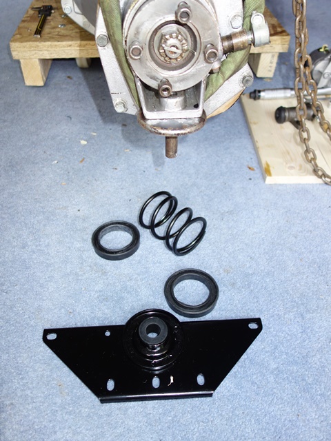
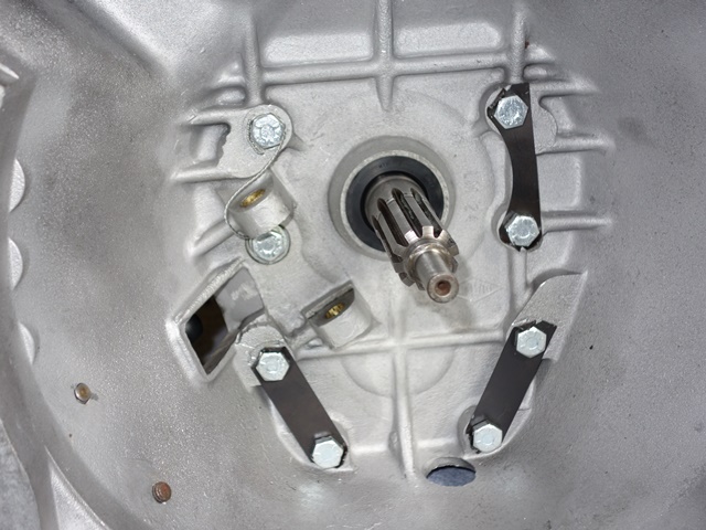 The bellhousing had already been ultrasonically cleaned and just needed the rear oil seal inserted before being bolted to the gearbox. Three lock tabs are used to prevent six of the bolts from working loose. The remaining two bolts, next to the clutch fork, use safety wire instead.