Apr 122013
 

The separate wiring loom for the starter solenoid relay was sent off to Autosparks so they could have a look and use it as a pattern to make up a new loom.

In the meantime, I’d posted my wiring dilemma on the E-Type forum to see if others could shed light on the relay wiring. A fellow S2 owner kindly pointed out that there was a change to this area of the wiring during the S2 production run. As it happens, at exactly the same time my car was passing through the factory. I guess that it hadn’t been reflected in the service manuals because the modification had been made mid-production run.

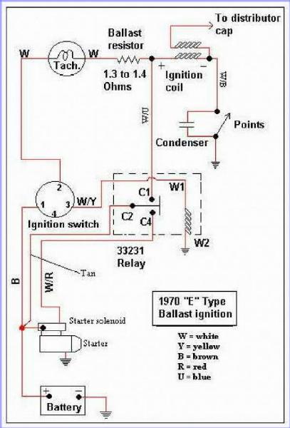
Around the end of ’69, a ballast resistor was introduced into the ignition circuit with the aim of improving cold starting. The original 3 ohm coil was replaced by a ballast resistor and coil wired in series, both being around 1.5 ohms. When the ignition switch is turned to start the engine, the starter relay activates, delivering power to the starter solenoid but also bypassing the ballast resistor.

Therefore when starting, the full 12 volts is applied to the coil. The spark energy is increased over the original setup as the current flowing into the coil is greater due to the lower coil resistance.

Once running, the ballast resistor is introduced back into the circuit. As the coil and ballast resistor have a similar impedance of around 1.5 ohms, the voltage drop across each is roughly the same. Therefore a voltage of 6v is applied to the coil during normal running.

I found the wiring diagram above on one of the American Jaguar sites which shows the wiring connections for ballasted cars. Autosparks also confirmed that they stock this ‘ballast resistor’ loom. Although I think I’ll get the car running before I cut and tape the unused wires in the main loom!

It was a good opportunity to get Autosparks to make up the additional wiring, using the correct colour coding, that I needed for the few upgrades I’d planned – the mechanical brake light switch to supplement the hydraulic switch and the boot light.

There was also a number of wires that I believe are missing from the sundries wiring pack, such as earthing wires for the rear light clusters and a beefier jumper wire between the two brown fuses. Touch wood, I’ve now got everything to complete the wiring.

Alas, it was again a case of one step forward and two back. Very early on in the work on the bodyshell, the LH outer pedal side panel had been replaced where the main loom comes out behind the voltage regulator bracket. The panel was from one of the main suppliers of panels so I foolishly assumed it would be spot on.

It was only once I came to fit the voltage regulator bracket that I found out that its mounting holes had been punched in the wrong place. They were about 5-6mm too close to the sill closing panel so that the bracket doesn’t fit. The bracket did change for the S2 cars so it might be that the panel also changed and I was supplied the wrong part.

Either way – not happy! I should have checked it well before it had reached the paint shop. It’s not the end of the world but it will always niggle me as I’ll know it’s not correct on the car. The annoying thing was I’d spent ages sourcing and refurbishing a replacement bracket, as the studs on the original had all sheared trying to remove it.

The first replacement was purchased from SNG but the fitting was incorrect, using bolts rather than attached studs. Some time later, I managed to get a rather tatty one on eBay which was covered in a mixture of black and green paint. It took several applications of Nitromors and wire brushing before it was good enough to be re-plated.

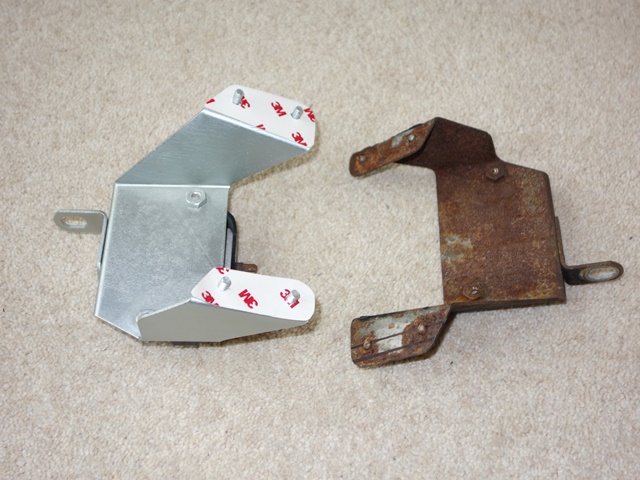
The problem I find with zinc plating is it’s too blingy (although I’m sure the brightness would dull slightly once exposed to the elements). I decided to experiment and sprayed it with a two-pack clear satin lacquer. The results were even better than I had hoped/expected. The satin finish obviously tones down the brightness but it also has a softer, smoother to the touch feel and a more uniform metallic finish.

After all that effort I didn’t really want to start butchering a perfectly good original part to fit. instead I planned to trim the original bracket to fit and then repair the welded studs but SNG Barratt now supply the brackets with the correct studs relatively cheaply. So I’ll adapt one of their repro parts rather than an original part.

I think I’ll also spray most of the plated parts in the engine bay with the clear satin lacquer. Hopefully it will also provide a more durable finish.

Apr 012013
 

As I’d spent many days meticulously labelling the new wiring looms using both the service manual and Coventry Auto Components diagrams and all the connections were accounted for, I foolishly assumed everything was correct. All that would remain would be to connect up the looms to each other and the corresponding components.

However I hadn’t checked back to the original loom … until now. The two looms are completely different for the connections to the starter solenoid relay, mounted on the engine bay bulkhead.

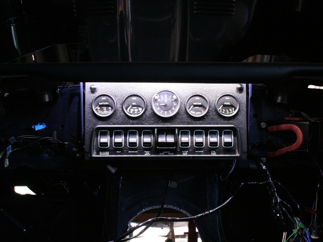
The relay connections on the new loom end close to the join between the dash loom and the RHS body loom, circled in Red in the photo. The ends are terminated with female spade connectors suggesting the relay is attached at this point.

However 1) there’s not sufficient length to route into the engine bay and 2) there’s no suitable exit hole near the relay into the engine bay.

So I can’t see how to route the new loom to the relay mounted on the bulkhead.

Where the new loom ends with the relay connectors, the original loom has both the larger current carrying wires for the relay (White/Red and Brown) wires cut, only the switching White/Yellow wire remains. The other end of the brown wire exiting the loom near the ignition switch is similarly cut. As both cut ends appear to be properly taped it could quite possibly be a factory modification, made retrospectively to looms that had already been delivered to Jaguar.

Current carrying wires cut

Brown ignition wire cut

I’ve not located the other end of the White/Red wire yet due to a slight mishap with a Stanley knife while cutting away the taping on the old loom. I’ve found the braided wires to be quite absorbent and the claret colour of blood does a splendid job at hiding the colour coding! Lesson re-learnt: cut away from fleshy bits, not towards!

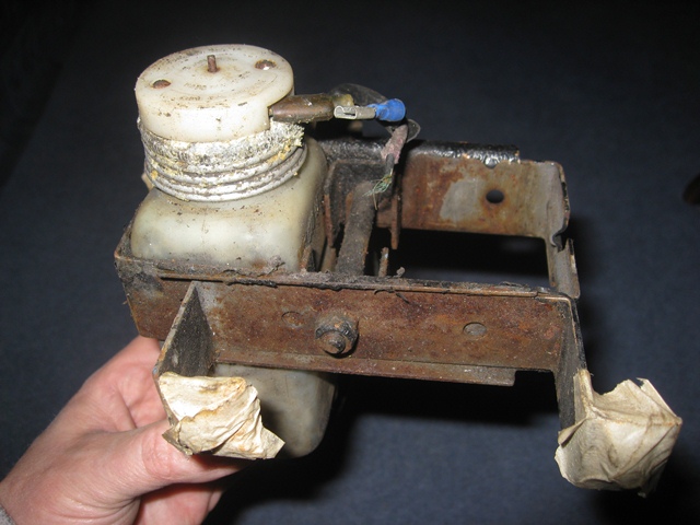
The relay was connected via its own separate loom, which also appears to be original (right). The routing of the White/Red and Brown wires, cut in the original dash loom, is directly between the bulkhead relay and the starter motor, ie doesn’t enter the dash area.

The switching White/Yellow wire is contained in a spur with sufficient length to reach the dash area from the engine bay via the hole high in the transmission tunnel panel.

So my current thinking is that this was a factory modification to keep the current carrying wiring away from the dash. Only the relay switching wire carrying a low current is routed into the cabin area.

I suspect this change may have been made during the S2 production run as I’ve not found any of the usual suppliers who sell a separate starter solenoid relay loom. I will have to ask Autosparks to make up a loom based on what remains of the original. The other issue is the original loom had a White/Blue wire connected to a central terminal on the relay. There’s no reference to a White/Blue wire in any of the wiring diagrams so I’m stumped what it is for at this stage.

I’ve subsequently found out that it was a factory modification after all. From chassis number 1R1393, just 28 cars before mine, a ballast resistor was introduced and the relay moved to the engine bay bulkhead.

The starter relay was changed so that it could switch two circuits – delivering power to the starter solenoid and bypassing the ballast resistor. The white/blue wire enable the ballast resistor to be excluded from the circuit on start up, increasing the current delivered to the coil.

Mar 212013
 

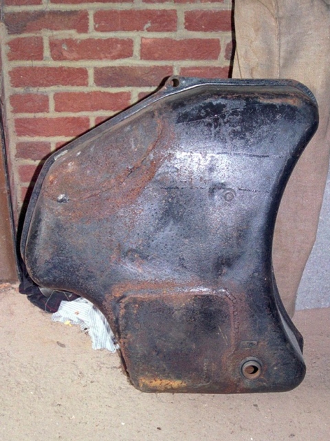
The fuel tank has been another area that hasn’t gone as smoothly as I had expected. At first glance the tank appeared to be fine however the problems were only revealed once it had been removed.

Over time the untreated tank had rusted through which is a common problem. It had been repaired by welding several replacement patches but the weld seams weren’t the best and had started to corrode quite badly.

My concern was the thickness of the tank, or lack of it, either side of the weld. I think water that had entered the tank must have been settling in the various troughs in the weld so it was again rusting from within.

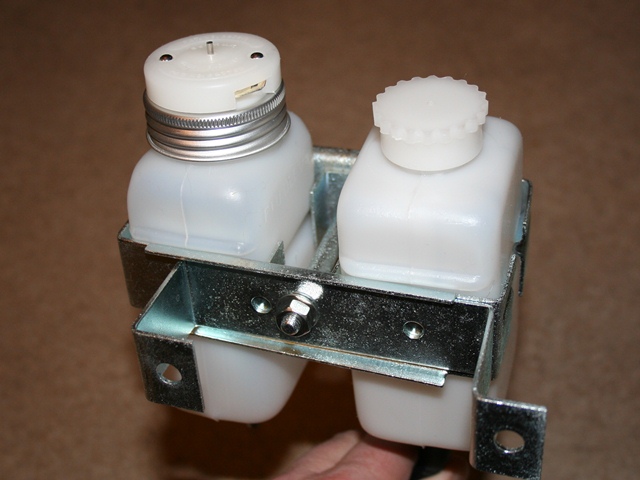
As luck would have it, there was an advert in a Jaguar magazine for an unused later S2 fuel tank. The S1 owner had purchased the tank unaware that the design had changed from a single breather pipe to three from chassis number 1R1393, some 28 cars before mine! In fact I wasn’t aware of a difference until I’d read his advert.

The three breather pipes were introduced with the addition of the expansion tank into the fuel system, late in the production run of the S2 cars. I think this is why it’s not referenced in any of the manuals.

A number of owners on the E-Type forum have reported running problems as a result of fuel starvation. Insufficient venting of the fuel tank was enabling a vacuum to build in the tank, acting against the fuel pump. A common remedy is to drill a small hole in the fuel filler cap. I can’t see how the addition of an expansion tank would alleviate this problem. The S1 and early S2 tanks were just vented directly to the outside rather than via an expansion tank. So fuel starvation issues may still be a problem …. but more of that later.

The replacement tank been already been treated with the white PVC type tank sealer. However, during the time it had been kept in dry storage, the sealer had started to crack and come away in sheets. It would all have to be removed otherwise it would quickly start to clog the fuel filters.

I started to research the different types of tank sealers on the market, mainly to find out the best method to remove the sealant used in my tank. The conclusion was that the PVC type sealers have very good coverage but don’t fill holes or seams well and have poor film strength. I’d found that out to my cost!! Most recommended using a paint stripper to remove it.

I had a large tin of Nitromors lying about so I gave it a go and poured it into the tank along with some nuts and bolts. The latter providing a mechanical method of dislodging loose bits of sealant. The problem with modern Nitromors is that they have changed its properties to a more gel like consistency rather than liquid. As a result it wasn’t very good at getting into the baffled areas.

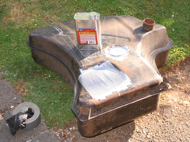
I then switched to Por-Strip which was better but didn’t reach much of the internal baffle surfaces. I needed a new approach.

One of the local powder coating firms offers a burn-off service but they didn’t want to do it as they were concerned the temperature would melt the brazing. Eventually I took it to a furniture restorer who was able to dip the tank. However the borescope revealed that there was still quite of a lot of sealant stubbornly attached.

I think paint stripper just softens the sealant which then becomes a sticky goo. Unless it is successfully removed immediately it simply sticks back to the tank surface as it dries out.

Like most troublesome issues, I put it to one side to have a ponder. I would tackle it at a later stage!

I recently found out that the PVC coatings can also be removed by dissolving in either Acetone or MEK (Methy Ethyl Ketone). Spurred into action once more, I ordered a small quantity of Acetone and added some sealant flakes to confirm it worked. 20 litres of Acetone have now been ordered and the tank is going to receive a thorough soaking at the weekend. Fingers crossed!

It still leaves the dilemma of how to treat the tank to avoid it rusting from the inside out. Not only that but it dawned on me that swilling around sealant inside the tank might cure the rusting problem but would be guaranteed to cause another. I’d realised that the PVC sealant had done its job and sealed the ends of all the internal pipes for the expansion tank connections.

Unless the Acetone can unblock them, I might have to resort to removing the brazed joints and withdrawing the pipes. I’m now wondering whether tank sealants might be the cause for some of the people suffering from fuel starvation problems.

 Posted by at 7:27 am
Mar 202013
 

A fuel expansion tank was added during the production run of the Series 2 cars, located in the boot space on the LHS rear wheel arch. The expansion tank is vented to the outside and so it’s internal pressure is always equal to the current atmospheric pressure.

Thermal expansion of the fuel increases the pressure in the fuel tank relative to the pressure in the expansion tank. As a result, fuel passes from the main fuel tank to the expansion tank until the pressures are equalised. As fuel is consumed or when the fuel contracts due to cooling temperatures, the pressure in the fuel tank decreases relative to the expansion tank. Any fuel in the expansion tank is then returned to the fuel tank as the pressures equalise once more.

Note: I have subsequently seen a Jaguar Service bulletin which indicated that fuel passes back from the expansion tank to the fuel tank by gravity, not pressure. Although with such a small bore for the breather pipes, I would have thought it’s probably a combination of gravity and pressure to overcome airlocks.

When the expansion tank was removed, I carefully labelled the various pipes between the two tanks with masking tape. For some reason I wrote the descriptions on the masking tape in pencil, which didn’t stand the test of time and were illegible by the time it was ready to be refitted. A lesson learnt!

A piece of 6mm jute was bonded to the tank as a protective layer between the tank and the wheel arch. However the bond was greater than the strength of the jute and so would need replacing. It’s available from most of the re-trimming firms and was bonded using the same AF178 contact adhesive used for the heat insulation.

I now had to work out how to make the connections between the two tanks as it’s not covered in any of the manuals available. The expansion tank has four outlets and the fuel tank only three. The additional outlet on the expansion tank is for the vent which exits to the outside via the boot drainage pipes. Although I believe the vent is connected to the emission control system for cars supplied to the USA.

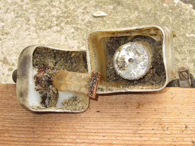
The first task was to work out the difference between the four internal pipes in the expansion tank. I used a length of garden wire with the end bent over to form a hook. This enabled the wire to be jiggled so that the hook engaged with the end of the pipe inside the tank and therefore could determine the internal length of the pipe.

Three of the pipes ran from the bottom to the full height of the tank while the fourth terminated as soon as it entered the tank, as depicted in the photo. The short red pipe (A) is at the bottom of the expansion tank and therefore must be for returning fuel to the main fuel tank. So I would expect this to be connected to a pipe which terminates fairly high up at the top of the fuel tank.

The other two blue pipes (B and C) terminate at the top of the expansion tank and so would be for the pipes passing fuel from the main tank to the expansion tank, when the main tank is full to the brim. The fuel entering the expansion tank via B & C would then fall to the bottom, to be returned via pipe A when the pressure in fuel tank reduced.

I would therefore expect B & C to be connected to pipes which would normally only be submerged in fuel when the tank is full, ie terminating at the very top of the fuel tank. It was now time to get the USB borescope out to investigate the fuel tank as ends of the pipes are hidden due to the internal baffles.

In fact the corresponding red pipe A in the fuel tank was easy to determine as the end of the pipe end can be felt via the large oval opening. The borescope did confirm that the other two pipes terminated at the top of the tank. The end of pipe A turns downwards for about an inch. I assumed two pipes are needed to pass fuel to the expansion tank due to the baffles. It shouldn’t matter how the B & C outlets are connected, ie B to B or B to C, as they are both performing the same role.

Anyway, assuming my logic is correct, I think I’ve worked out the correct connections!!

 Posted by at 10:35 am
Mar 042013
 

The final task to complete the heat insulation was to install the Koolmat in the cabin area. My main concern had been the ability to be able to bond the underfelt to the silicone side of the Koolmat. A number of adhesives were tested using off cuts of Koolmat and underfelt. Normal silicone sealant was found to be the best product by a considerable margin, which alleviated my fears.

However I’m now leaning towards replacing the underfelt with some 1/4″ Dynaliner when the final trim goes in. The combined thickness of the Dynaliner and Koolmat would be closer to the original bitumen sound insulation with underfelt and so there shouldn’t be clearance issues with the central console. Also the underfelt was destroyed when it was removed during the adhesive tests and so would probably cause more headaches if (when!) the trim needed lifting in future.

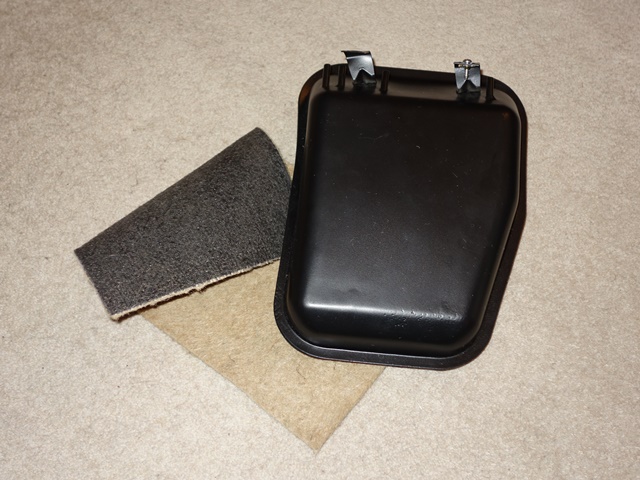
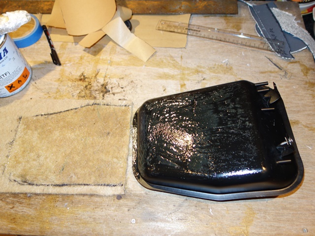
The Koolmat instructions suggest starting the installation with the toe box and then work backwards. I decided to do the two panels under the seats first, rather than dive straight in, as I’d not used the ALPHABOND AF178 high temperature contact adhesive before. This would provide a few easy panels to become familiar working with the adhesive before having to assume contortionist positions to install the toe box area.

Holes were cut in the Koolmat for the seat belt mounting and seat runner fittings, the latter would be screwed in place during the gluing to ensure good alignment. However, when the Kootmat panels were trial fitted, they would not lie flat on the floor as the ends of the Huck bolts for the radius arm mounting protruded above the floor pan. To overcome this an off cut of brake piping was used as a punch to cut out suitably size holes in the Koolmat, just about visible in the photo above.

The AF178 contact adhesive needs to be applied to both surfaces and then allowed to become touch dry, when it no longer lifts away when touched. The Koolmat can then be pressed in place. I chose to apply the adhesive using a brush and purchased a small wallpaper roller to apply pressure once in place, which was a good buy.

The contact adhesive certainly lives up to its name as there’s almost no opportunity to reposition the Koolmat once the two surfaces have made contact. As a result, the alignment of the first few panels was acceptable rather than perfect. I was glad I had started with the easier under-seat panels first. I then started adding alignment markers on the Koolmat and bodyshell during the trial fitting which help enormously during the final fitting, when you needed to get it right first time.

Martin Robey replacement floorpans had been fitted during the bodyshell rebuild. These are manufactured to cater for both the non-flat floor Series 1 and 2 cars and therefore have two separate sets of seat runner mounting points. The unused mounting points and floorpan holes were blanked off with short bolts and blanking grommets (9mm & 19mm) respectively to ensure the floor was watertight. I’m assuming the various floorpan holes are to provide drainage should it ever be required.

The instructions on the AF178 tin are conspicuous by their absence. I wanted to take my time and planned to install the Koolmat over several days, and therefore needed to clean the brush. The manufacturer’s ‘technical’ department wasn’t particularly helpful with their suggestion to use ‘a solvent’. I would never have thought of that! When pressed on the type of solvent, they didn’t know, and it took trial and error to determine it needed to be cellulose thinners.

I wasn’t too impressed with the accuracy of pre-cut kit supplied by Koolmat and if I were to do it again would probably purchase a roll of Koolmat and cut it from templates I made myself.

I think the person cutting the kits must have been working from memory and from a car they’d only seen once. I very much doubt they had ever fitted one of their kits!!

The issues that needed to be worked around were:

  • They suggest making incisions at each corner for the piece covering the lowered floorpan area. A much more effective way to mould it to the floorpan and avoid crumpling was to cut out narrow wedges perpendicular to the length of the floorpan as shown in the photo above.
  • They provide a piece to cover the area between the lowered floorpan and the toe box. This piece bears no resemblance to the area it is intended to cover. In the end I cut this into two small pieces for the floor, in front of and behind the lowered floorpan, and two very narrow strips to run along the outer edge.
  • From their installation photos, Koolmat simply cover over the gearbox cover. Therefore the two lower side pieces for the transmission tunnel around the gearbox were far too high and required trimming. They now finish just below the transmission/gearbox cover so the cover could be removed for maintenance.
  • The same transmission pieces overlapped the rear transmission tunnel piece by such an extent, that it was almost pointless fitting the latter.

To be fair to Koolmat, at least they provided a reasonable amount of off cuts to be able to complete the job where gaps existed.

The gluing of the Koolmat to the gearbox cover will wait until the trial fitting of the interior trim, including carpets, just in case there are issues with clearance. Finally a bead of silicone sealant was run along all the joints in the Koolmat.

Feb 142013
 

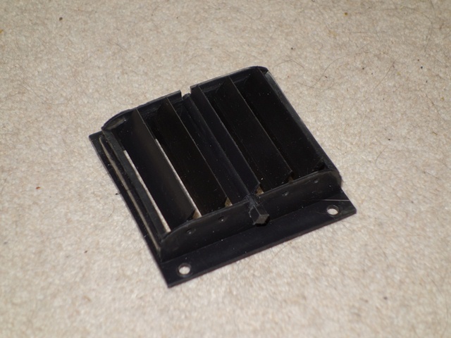
The dash heater controls operate plastic vent outlets on the underside of the dash, one in each footwell. When the vent is open, the air follows the passage of least resistance into the footwells. By closing the vent, this path is blocked and therefore the air is forced to exit via the dashtop windscreen vents.

The vents themselves consist of five interconnected vanes with the central vane connected to the dash control. Operating the dash heater control rotates the central vane, and with it the other vanes, between the fully open and fully closed positions.

Somehow the central vane of one of the vents has either been misplaced or lost during the constant sifting through the boxes of parts. Unfortunately the vents seem to be unique to the Series 2 and, as far as I’m aware, are not available any more.

After fruitless searches of the parts boxes and keeping an eye out at Stoneleigh spares day, I had to bite the bullet and start researching if and how I could fabricate a new vane. The problem is that without the central vane the vent is useless.

I think most plastic parts are generally injection moulded which isn’t really a DIY option. However there are some very low viscosity polyurethanes available that are suitable for moulding which may produce a good replacement. At least having two vents meant I still had a central vane to make a mould from!

A order was placed with MB Fibreglass Supplies who were very helpful in explaining the moulding process and several days later some RTV Silicone Mould Making Rubber (Polycraft GP-3481), Fast Cast Polyurethane Liquid Plastic Casting Resin (Polycraft FC-6720) and black polyurethane pigment arrived. Some white modelling clay (water clay) was also required, which can be obtained from most craft suppliers.

The first step was to produce a two piece silicone mould of the vane. Four ‘L’ shaped pieces of plywood were fabricated with a depth of around 3″ to make a mould housing. Using ‘L’ shaped pieces has several benefits; they can easily be moved relative to each other to obtain the desired mould footprint, clamping together is straightforward and they can easily be removed at the end without damaging the mould.

The mould housing is then half filled with the modelling clay and clay rubbed along the each of the corner joints to seal them. An off-cut of wood and some coach bolts was used as a mini tamping device. The vane was then pressed into the clay until the long lengths of the vane were flush with the clay (ie half above and half below the clay). Finally a number of indentations were made in the clay which will act as key for both sides of the mould.

It was now time to make the first half of the mould with the two-part silicone system, mixed by weight – 10 parts rubber to 1 part catalyst, ably assisted (hindered) by my two nieces who were on mixing and pouring duties. Being a red colour, it was easy to see when the catalyst had been fully mixed into the white rubber part. The mixture was then slowly poured into the mould housing, covering the clay and vane. The technique is to pour slowly and in the same place so that the silicone pushes out the air as it flows over the part being moulded.

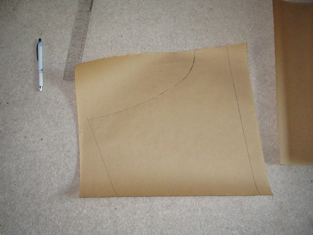
The Room Temperature Vulcanizing (RTV) silicone normally cures in around 4 hours although I left it overnight as a precaution as it still felt tacky after 4 hours, probably due to the cold weather. The mould housing can then be turned over so the clay can be removed, to reveal the first half of the silicone mould with the clay indentations now appearing as small peaks.

Traces of residual clay were removed by wiping with a damped cloth to prepare for the making of the second half of the mould. Once dry, the first half of the mould was lightly brushed with Vaseline, diluted in white spirit.

This should act as a releasing agent stopping the second half of the mould sticking to the first. Some more two-part silicone was then poured into the mould housing as before and again left overnight to cure. Now for the moment of truth …. will two halves separate?

They actually separated very easily and the original vane came out without damaging the mould. The quality looked very good although the proof will only come once the new vane had been cast. The final preparation of the mould was to cut a conical channel for pouring in the polyurethane casting resin and an air vent to help prevent trapped air bubbles in the cast.

The polyurethane resin used was a two part product which naturally cures to an ivory white colour so a small amount of black pigment is required to get the desired finish. The mixture ratio by weight of resin part A, part B and pigment was 10:10:1 so the main difficulty was weighing the three parts accurately as the part only weighs 4 grams.

The resin cures in approximately 60 minutes so it wasn’t long before the first cast was ready. The initial impression was very good – even the original casting marks were faithfully reproduced. However the part was far too flexible so the nieces rudely declared it a ‘FAIL’.


MB Fibreglass Supplies were again helpful and thought the cure process had probably been compromised, most likely caused by having insufficient temperature in the component liquids when they were mixed.

A second casting was made after first heating the liquids on a radiator. This produced a much stiffer vane which seemed to stiffen even further once it had been removed from the mould and left on the radiator overnight. I now had two operational heater vents!!

Feb 012013
 

The map light on the underside of the dash isn’t that bright and so is being replaced by a string of three pure white LED strips; two outer 15cm lengths and a central 10cm length.

I added the middle length in an attempt to make sure the central area, where the standard bulb fitting is located, had equal illumination. The strips are backed with a 3M adhesive tape so it is simply a matter of removing the backing, pressing into place and connecting to the wiring loom via bullet connections.

Heatshrink tubing was used to tidy up the connections between the three strips and hide my dodgy soldering. All that remained was to temporarily fit the dash top to test.

Testing of the Map Light

The minimum order for the pure white LED strip was 2 metres so I had more than 1.5m left over. It seemed a waste not to use it so I looked to see if it could be used ‘tastefully’ elsewhere but was mindful of avoiding making the car look like a victim of a fight with the Halfords aftermarket department!!

A discreet light in the boot, operated when the bootlid is opened, will be covered at a later stage ….

Jan 292013
 

Even though the pipe end centres were 6mm too wide, there wasn’t sufficient flex in the pipe to ‘persuade’ it to go in. When I originally measured the centres distance of 22¾” (578mm), the accuracy of the measurement wasn’t helped by the fact that there wasn’t a clear line of sight between the holes on the bulkhead as the engine stabiliser bracket is in the way.

At least the fabricated pipe could now be used to obtain an exact spacing of the bulkhead holes. The pipe was cut in half, shortened and a dowel inserted. The two halves could then be adjusted on the dowel to fit the bulkhead. The correct centres distance was 3/32” shorter than my original measurement …. ooops!

A while later, the MkIII heater pipe was dropped off …. would it fit and would the saga be over?? As soon as I got back from the office I dashed into the garage to trial fit the new pipe. It was spot on, much to the relief of all concerned!

A mock up of the bulkhead was made in aluminium sheet to ensure everything would fit this time around

It was suggested to re-title the blog entry to ‘How my F1-engineer-mate made a bl00dy great meal of remaking a simple water pipe’. The irony is even that was too long for the blog title field! Anyway, the reason the first pipe didn’t fit was as much down to my inability to use a tape measure as it was in the fabrication.

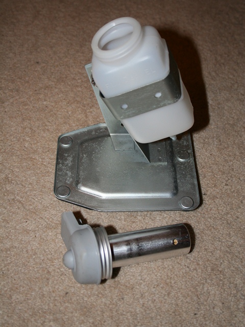
The photo shows the difference in the bend radius between the two pipes. The tighter bend in the MkIII version means the pipe is perpendicular where it passes through the flange.

The heater pipes are one of the first items that need to be installed on a rebuild so I was looking forward to fitting them at last and cracking on with the rebuild.

I should have known better …. the collar on my rivet gun is too wide, so it fouls on the protruding pipe and can’t reach the rivet head! How can something a simple as a heating pipe cause so much grief?!?

Jan 232013
 

The brake reservoir caps house electrical connections for the float operated switch for the brake fluid warning light and appeared to be quite corroded. It was only once they had been opened that it became clear that what I thought was corrosion was probably crystallised hydraulic fluid.

Both the reservoir caps appeared to be corroded but it was actually crystalised hydraulic fluid This was most of the contents of the first reservoir! The second reservoir was not much better!

The float should be enclosed in an aluminium cylinder but most of this had corroded away. I had little option but to replace the reservoirs which was a shame. Replacements are readily available however an alarming number of people had reported problems with them splitting and the resulting leak causing havoc with the paint work.

Reading other people’s woes with the repro products, I think the splitting might be initiated either when the black low pressure rubber tubing is pushed on, as a reasonable amount of force is required, or by over-tightening the hose clamps. Basically the new parts are not particularly good quality and no doubt originate from China.

The original bottles had a metal insert inside the supply protrusion/outlet which would avoid the over-tightening issue. The insert also had a gauze nylon filter, again missing from the new ones.

The clutch reservoir was better as the fluid hadn’t crystalised, which I’m now thinking might be caused as the aluminium float shroud corrodes. However there was a lot of gunk at the bottom so I thought it wise to replace as well.

Reservoir cut open to retrieve the metal insert

I decided to salvage the metal inserts by cutting the bottles in half. These were zinc-nickel plated along with the bracket clamps before being inserted into the new bottles. The method I use to insert them was to pass a piece of string through the supply outlet to act as a guide.

A rod was then used to carefully push the insert home while supporting the other side to minimise the stress on the plastic bottle. The reverse was done when pushing on the low pressure rubber tubing, opposing the pressure with the same rod. Hopefully it will be ok.

I couldn’t work out a method of refitting the nylon gauze filter on to the metal insert once it was in place. The filters were not in the best of shape so they have been omitted.

Brake and Clutch reservoirs reunited with re-plated bracket Brake Servo reservoir showing the aluminium shroud around the float

However this does lead on to my next dilemma. As the calipers have been reconditioned and the reservoirs and hydraulic pipes replaced, I have the opportunity to switch from DOT4 to silicone brake fluid.

I like the idea of using the silicone fluid to avoid potential future problems with leaks damaging the paint work, especially in light of the problems others have had with the new reservoir bottles. Conversely there are views that the rubber seals can be damaged over the long term by the silicone.

It seems there isn’t a general consensus on which is the best way to go and it’s difficult determining whether advice is based on fact or merely that the person went down that route themselves and therefore it must be the right choice! Hmmmmm ……

Jan 202013
 

Several people had mentioned issues with heat soak due in the footwells due to the proximity of the exhaust. I was interested in avoiding this because I’ve had the same issue in my Elise while on long continental drives. I also remembered an article in one of the Jaguar magazine years back recommending lining the transmission tunnel with a reflective heat covering to reduce the heat coming into the cabin.

My main concern was to rebuild the car and then regret not fitting a reflective heat shield as it would be far harder to change my mind later on. Therefore, as a precautionary measure, I decided it was best to line the transmission tunnel now rather than later – probably overkill but hey ho.

After a little research into reducing exhaust heat, I went for a product from Zircotec which seemed to fit the bill. Their heat shield material comes in sheets and in three different thicknesses. The thinnest sheet should be sufficient as additional heat insulation was also being installed within the cabin. I’m glad I didn’t go for the next thickness up as I subsequently used the middle thickness Zircotec sheet to make a replacement exhaust heat shield. It would have been a little too rigid to mould to the curves of the transmission tunnel.

Paper templates were made to determine the smallest size of sheet needed (it's quite expensive!) Four pieces were required: two for the front footwell area, two for the transmission tunnel around the gearbox

Paper templates were made up to cover the transmission tunnel from the front of the footwells back to where the transmission tunnel becomes enclosed, near the handbrake. The templates could then used to determine the size of Zircotec sheet required and then to cut out once it arrived.

The installation was really helped by making accurate templates to cut out the Zircotec sheets rather than try to re-shape in-situ. I ditched the original paper ones as they were too flimsy. In the end I used the clear sticky-backed plastic sheet that was often used to cover my school books of old.

Next is the installation of the Koolmat cabin insulation ….