Jan 162013
 

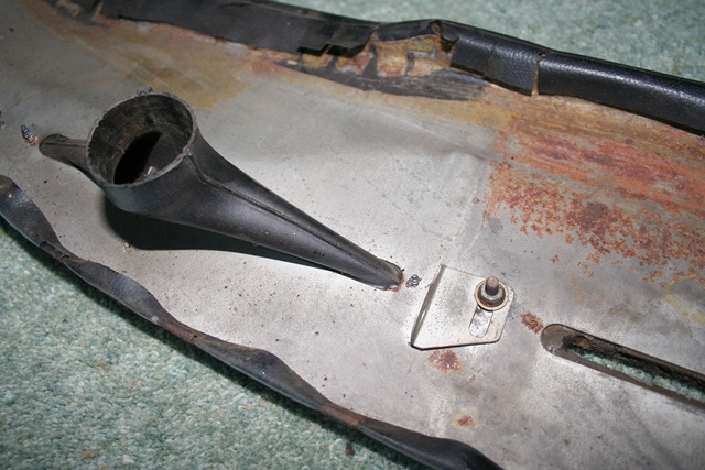
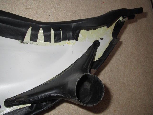
Various sections of the exhaust heatshield which protects the brake servo unit had snapped off. I believe the material used contained asbestos and, for obvious reasons, is no longer available. So I needed to look for a replacement and wasn’t too impressed with what I found on offer, mainly the price!

A top corner and a considerable portion of the other side of the heatsield had snapped off The brackets used to mount the heatshield to the engine space frame

I suspect the fragility of the original heat shield is a common problem as a number of others had reported sections had broken off. The repro offerings from the usual players where simply bent sheets of either stainless steel or aluminium plate.

They would provide a physical barrier to limit the areas affected by thermal convention. However, without some form of insulation on the surface facing the exhaust, I thought the shield would get very hot and then conduct heat to the surrounding areas. Some form of heat insulation might be a good idea.

A photo posted by a member of the E-Type forum showing the difference between the original and aftermarket heatshields
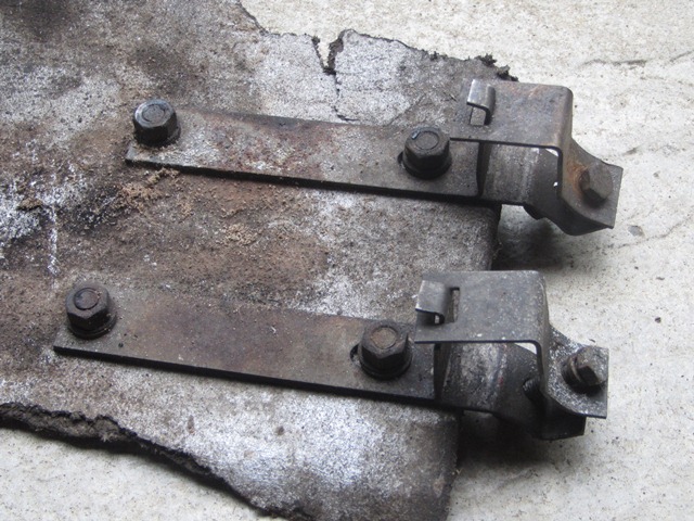
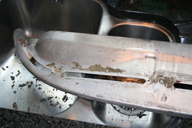
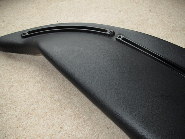
The photo to the right (posted by a member of the E-Type forum) also shows the differences between the original and repro shields. You’d have thought they would have at least made an attempt to get the size correct but I guess it would provide a greater physical barrier.

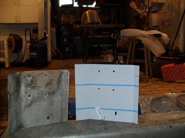
The forum member was also kind enough to post the overall dimensions of the shield. That, coupled with the piece I had remaining, meant I could at least have a stab at fabricating my own.

Also the price was excessive as usual, coming in at around £45 once P&P had been added. The sheet of aluminium purchased to make my own was only £7.50! (Although I ended up far exceeding the £45 when I decided to add the thin heat shield material!!)

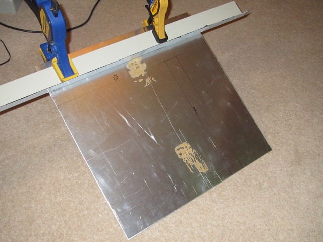
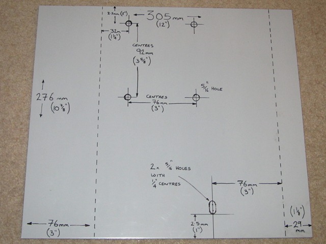
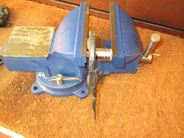
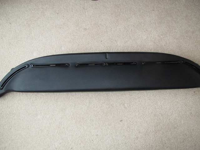
The original is approximately 3mm thick so I ordered a suitable sheet of 3mm aluminium plate. With hindsight I probably should have opted for 2mm plate as this would easily have been sturdy enough and less weight. The aluminium plate was first cut to size using a jigsaw run along a straight edge to ensure neat edges.

The mounting holes were then drilled and the lower oblong mounting slot profiled from two 5/16″ holes using a dremel. Being aluminium it was very easy to work with, both cutting and drilling.

A length of steel angle (actually some shed roof edging) was used to make sure the aluminium plate was cut to size with straight edges The fixing holes and various dimensions were mapped out on the protective covering - measure twice, cut once etc! Another photo posted by the forum member showed the two bends were roughly the same angle

I now had the problem of getting neat bends into the flat sheet as I didn’t have any sheet metal equipment. The 3mm plate is quite rigid so I was concerned a DIY Heath Robinson solution to bend it would more than likely end up with me making a pig’s ear of it. So I popped out to a local fabrication company to see if they could help.

I think they’re more used to large volume commercial clients! However as it was lunchtime they weren’t busy and one of them kindly offered to put the bends in there and then. The machine used to bend sheet metal was computer controlled press about 15′ long. A few taps later, to program the sheet thickness, distance of the bend from the edges and the required angle, and hey presto! A neatly bent heatshield was returned. Not only that but he wouldn’t take any money for his time!

All that remained was to cover the exhaust side with a heatshield material, rather than leave as bare sheet metal like the repro items. I obtained some self-adhesive heatshield material from a company called Zircotec to line the transmission tunnel area and so also purchased a sheet of their thicker Zircotec II for the heatshield. It might provide a little more protection.

A sheet of Zircotec II was cut slightly oversize to cover the exhaust side of the heatshield The finished heatshield!

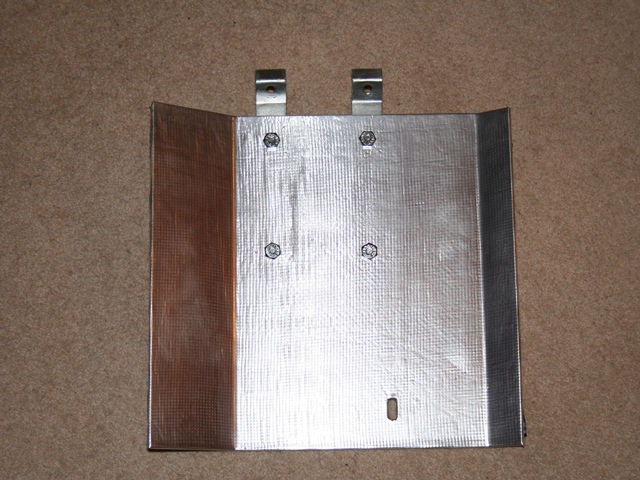
The Zircotec sheet was cut 20mm oversize to provide a 10mm excess which could be wrapped around the edges. I was quite pleased with the final result.

Jan 152013
 

Unfortunately the number and quality of the photos taken of the routing of the wiring looms during the dismantling was woefully inadequate! The three photos below were the only ones of any use but at least they gave a starting point for the main and dash looms.

The main, dash and alternator looms route behind the glovebox. The dash loom joing the LHS body harness in this corner The fuse boxes and wiring looms behind the centre console The dash loom behind the steering column mount

Dash Loom
The dash harness was first to be fitted and it’s fairly obvious how it is routed as it is just held in place by the protruding tabs along the dash length. The tabs were covered with heatshrink to avoid chafing. Its lateral positioning was determine by referring back to the dismantling photos and the group of mainly green and purple wires needs to be directly below the right hand fuse boxes.

Main Engine Loom
The engine and front lighting loom was next to be added. The length running in the cabin also runs behind the same protruding tabs. The loom then passes through into the engine compartment via a hole in the left hand footwell and along the upper tube of the left sub-frame. The alternator spur is fixed to the sub-frame with a P-clip. The remainder of the loom passes down, across and then up the picture frame and finally back along the upper tube of the right sub-frame. Two more P clips, on the bottom bolt of each of the upper front wishbone brackets, are used to secure the loom to the picture frame.

Alternator Loom
The alternator loom follows a similar route as the main engine loom using the same hole in the footwell. Obviously only going as far as the alternator.

Fan Looms
The fitting of the fan looms will have to wait until the fan relays and fans have been installed.

Re-wiring starts with the dash loom

Left & Right Hand Body Looms
The routes of the two body looms are a mirror image. They start just below the windscreen pillar where they are connected to the dash looms. From here they drop down and travel forward running behind a protruding tab which can be bent back to secure it in place. They then run within a indented channel on the inner sill until they reach the rear bulkhead.

They pass up the bulkhead/wheel arch join, entering the boot space via holes in the vertical section of the rear bulkhead. Inside the boot space, they run directly upwards and then rearwards behind more tabs before passing into the wheel arches via holes just behind the bootlid hinges.

EDIS Megajolt Looms
As I had opted to install EDIS Megajolt electronic ignition system this will need to be installed before the other dash components are put in but I’ll cover this installation in another entry.

A problem solved ….
One issue has now been resolved. During the labelling of the looms I found that they were missing the green & brown wire for the reverse light switch. There’s a sundries wiring pack that is needed in addition to the six main looms and it contains the separate wires such as the reverse wire, dash illumination and a few switches/gauges wires.

Jan 152013
 

Sound Insulation
The original sound deadening was provided by thin, perforated sheets of a bitumen type substance. I’m not sure if this is still available but there are a number of alternative products available, all of which have self-adhesive backing. Essentially all a sound deadening material does is add mass to the panel to stop or reduce its tendency to resonate. The more mass, the greater the sound deadening.

The product I decided on was Dynamat which is 1.7mm sheets of butyl rubber, covered in a metallic sliver foil to reflect heat. It normally comes in 18″ x 32″ sheets which can easily be shaped with a Stanley knife. Quite a few have used it in restorations covering the whole floor, footwell and transmission tunnel areas to stop heat soak from the engine bay into the cabin. Although I wasn’t convinced of its suitability for heat insulation and so will only be using it for sound deadening, in the following areas:

  • Door skins
  • Rear bulkhead in cabin
  • Boot floor

The only difficulty was the door skins due to the limited access. A paper template was used to obtain the shape necessary to cover the door skin, leaving an uncovered 1cm strip around the perimeter. This was to allow the waxoyl to seep as far into the door frame to door skin joint as possible.

Tapping the large flat panel under the fuel tank resulted in quit a loud drumming sound so soundproofing was added to this area The doors were quite difficult. No only just to get the Dynamat into the door space but then to remove the adhesive backing while in-situ The rear bulkheads got the same treatment. I'm still undecided whether to do the vertical panels up from the floor due to the type of trim used there

The main mistake I made was to try to cover the area high up on the leading edge of the door, above the hinge area. There’s barely enough room to get the sheet in so the backing had to be removed before it was put into position. So it naturally stuck to the surrounding areas as it was manoeuvred into place.

I’m not sure whether it is a good idea to use Dynamat on the vertical panels coming up from the floorpan as these will be trimmed with moquette, which is quite thin so the imperfections (creases) in the Dynamat may show through. I’ll decide later when I come to install the trim.

Heat Insulation
The reason why I wasn’t convinced about the Dynamat for heat insulation was that the reflective layer was innermost – ideal if you wanted to retain heat within the cabin but possibly not that effective against heat soak from the engine bay.

The Koolmat at the top is woven glass fibre covered with a grey cured silicone. Below is the type of fibrous trim backing that needs to be bonded to the silicone side
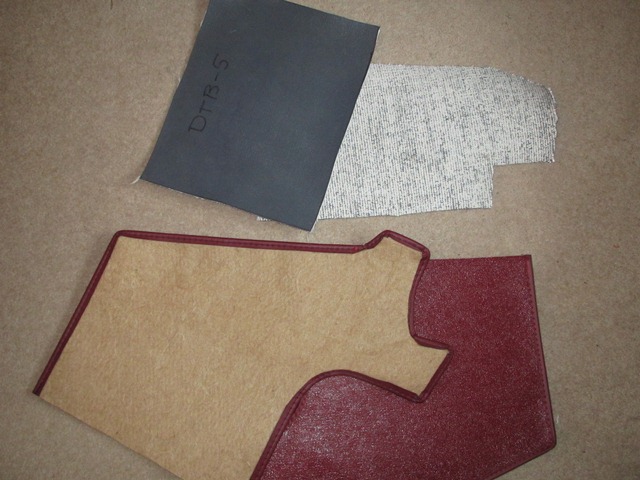
Another product on the market is Koolmat which looked far more promising. It’s woven glass fibre covered with a grey, cured silicone layer and is designed as a barrier for conducted heat. Being quite dense, it also act as a sound deadening layer.

Koolmat is much cheaper in the US and, as luck would have it, a relative was coming over so I asked if they would be able to it back for me. I think it took up almost half of their luggage weight allowance!


The Koolmat kit for the E-Type contains 20 pre-cut pieces and some high temperature silicone sealant. The white glass fibre side is bonded to the car body with a high temperature contact adhesive and the sealant then used to seal the butt joints where two pieces meet.

A short time after, I was dropping the seat frames and centre console off at Suffolk & Turleys. They had come across Koolmat but weren’t too keen on it, as it’s difficult to get anthing to bond to cured silicone. I had a similar reaction from Andy when I dropped into Hutsons.


A comparative test was done to select the best method of bonding the trim to the Koolmat's cured silicone sideNow I was really concerned that I’d gone for the wrong product. However one of the knowledgeable folk on the E-Type forum suggested it was a good product and they didn’t have any problems.

However I wanted to make sure it would be possible to bond the underfelt to the silicone side before even considering installing the Koolmat.

The Alphabond AF178 contact adhesive simpy peeled away. This will be used to bond the Koolmat to the body but Allbond Silicone Sealant will be used on the grey side.Several phone calls later to get advice from various adhesive companies and it was time to perform a comparative test. Off-cuts of jute and Koolmat were used to test the bond for number of different adhesives and sealants.

The best by a significant margin was your standard bathroom silicone sealant! I guess that shouldn’t have been such a surprise – the only thing that sticks to silicone is silicone!

The image, above right, shows problem of bonding to silicone. It shows the test of Alphabond AF178 contact adhesive verses the eventual winner, Allbond Silicone Sealant. The Alphabond AF178 is the contact adhesive that will be used for bonding the glass fibre side of the Koolmat to the body. However when used on the silicone side, it simply peels away from the silicone. With the sealant, the bond is strong enough so the fibrous jute fails before the bond.

So a clear (rather than bathroom white!) Allbond Silicone Sealant will be used to bond the interior trim to the Koolmat. I’ll cover this at a later stage.

I’m also planning to cover the area in the engine bay around the gearbox and transmisssion tunnel with the Zircotec I heatshield material. With luck, this should reflect much of the exhaust and engine heat back into the engine bay.

Jan 012013
 

The backlighting of the dash gauges is provided by incandescent bulbs inserted into the rear of the gauges and is fairly poor by modern standards. The green hue of the backlighting is achieved by coloured plastic covers within the gauges and green plastic tape behind the switch legend strip. However the heat produced by the bulbs had melted several of the covers.

The backlighting can also be set to Bright, Dim or Off via the 3-way Panel Switch. The light produced by these bulbs is almost linear to the applied voltage. When bright is selected, 12 volts is applied across the bulb terminals. While switching to Dim introduces a resistor in series with the bulb. This produces a voltage drop across the resistor and therefore the voltage applied to the bulb and the emitted light is reduced.

One popular ‘upgrade’ is to replace the bulbs by LED strips mounted around the perimeter of the inside of the gauges. LED strips are available either containing a single LED colour group (eg white, red, green, blue, yellow) or all three of the additive primary colours; red, green and blue.

The latter, for obvious reasons referred to as RGB LED strips, can output different light colours by adjusting the relative intensity of each LED colour group. The LED strips also have the advantage that they are more efficient and do not generate a large amount of heat.

The upgrade is well documented in Stéphane’s guide on the E-Type forum. One of the members had tried the upgrade with blue LEDs and I thought this would suit my car, being Opalescent Dark Blue, but I was undecided whether I wanted to lose the original green.

I couldn’t decide which I preferred so I investigated the possibility of being able to switch between the two. In the end I decided to use the RGB LED strips and somehow try to use the spare dash switch (used for the heated rear window on the FHC) to toggle between green and blue. This would lead to numerous problems that would only become apparent as work progressed.

The LED strips currently on offer vary in the number of LEDs per metre; typically 15, 30 or 60 LEDs per metre but also in the strip width; either 8mm (3528 chipset) or 10mm (5050 chipset) and with or without waterproof covering. The aim was to increase the brightness of the backlighting but with the constraint of space within the gauges. So I thought the thinner strips with the waterproof option would be sensible, so I ordered the following:

  • 2 metres (min order) of 3528 Pure White 60 LEDs/m – for the dash map light
  • 5 metres of 3528 RGB 60 LEDs/m – for the gauges

The strips with 60 LEDs per metre can be cut every three LEDs, ie every 5cm. This was ideal as the inner circumference of the smaller gauges would allow a 10cm strip. However the first problem came to light, excuse the pun, when I tested the 3528 RGB strip. This chipset used has one LED for each of the three primary colours in a 5cm strip. When either blue or green is selected, only one of the three LEDs was illuminated. So in the 10cm strip possible, lighting would only be provided by two LEDs – hardly an improvement!

After a few calls to suppliers, it became clear that I needed the wider 10mm strips for the multi-colour option. Each LED in the 5050 chipset is effectively made up of three LEDS; one for each of the red, green and blue colours. So all six LEDs in the 10cm strip would provide light. If the additional width caused a problem I would give up on being able to switch colours and revert back to a single coloured 8mm strip.

While I was planning how to incorporate the upgrade into the existing switch layout I noticed something really odd in the wiring diagrams which I couldn’t understand. The power for the dash illumination is only provided when either the side or main headlights are on. This made perfect sense – if it’s dark enough to need lights then you’d always want to illuminate the gauges. So why did the Panel switch have three settings: Bright, Dim and Off? Why on earth would you ever want to have the side/head lights on and not the dash?

I started to doubt the wiring diagram and so posted the question on the forum. Apparently in the 60s it was a legal requirement when parking at night to have the side lights on. In which case the dash illumination was turned off to conserve the battery. I don’t think I’ll ever need his feature so I’m considering swapping to a two state Panel switch – Bright and Dim.

With the planning done, the next step was to start to dismantle the gauges ….

Dec 282012
 

The seats had been a nightmare to remove from the car as the securing bolts were rusted solid and it was virtually impossible to get any penetrating oil into the threads due to the hardura trim beneath the seat. It also became clear that there was a fair amount of movement between the seat bases and the seat backs which would need to be invesitgated and addressed.

The seats in the S2 had the benefit over the earlier cars of being able to recline. The seat base and the seat back are joined by reclining mechanisms at each side, which are operated via a chromed lever. In normal use the seat back is locked in position by the engagement of toothed components within the mechanism.

The operation of the lever disengages the teeth, therefore allowing the seat back to move relative to the seat base. A connecting bar runs behind the seat so that the reclining mechanism is activated on both sides simultaniously and return springs ensure that the mechanisms return to the locked state when the lever is released.

The reclining mechanism showing the connecting bar which operates a toothed locking mechanism and also one of the return springs

The reclining mechanisms are attached to the seat backs by two countersunk screws at each side

Pressing out the connecting bar guides

There were two causes for the excessive movement. The first was as a result of stretching in some of the countersunk holes, for connecting the mechanism to the seat back. The second was due to the loosening of the pivot joint between the two halves of the mechanism.

The pivot joint consists of a round metal cylinder which is lipped at one end. This passes through the outer half of the mechanism until the lip is flush and then through the inner half of the mechanism. It is then MIG welded to the inner half. The pivot joint is cylindrical as it also acts as the pivot for the connecting bar, which has protrusions at each end which pass through the pivot centres.

The pivot joint was very loose on two of the mechanisms and had obviously been meddled with by a previous owner, probably trying to address the excesive play. So I thought it would be a good idea to dismantle them so that they could be repaired and painted.

With hindsight I don’t think they are designed to be dismantled as, to do so, requires the welded pivot joint to be pressed out to provide enough movement to disengage the various parts. I think this must have been what the previous owner had tried before giving up. However I’d reached the point of no return!

Dismantled at last Damage bolt hole In need of repair

The dismantled reclining mechanism. The reclining connecting bar interlocks with the toothed wedge piece to lock and release the seat back

The two parts show where the attachment hole has been stretched, causing excessive movement in the seat backs

The parts were shot blasted and the damaged ones repaired by adding new metal and then grinding back to the correct profile

The welds securing the pivot joints were ground down so that only a small amount of weld remained. They could then be pressed out using a vice. This provided sufficient movement of the connecting bar to disengage it from the interlocked toothed, wedge shaped piece (above left) while withdrawing it from the mechanism. In doing so the two halves of the mechanism then fell apart.

The individual parts were then shot blasted before new metal was added to the parts requiring repair to the stretched bolt holes. They were then ground back to the correct profile. All the parts were then painted in POR15 in preference to powder coating as I felt POR15 would give a much tougher finish.

Painting with POR15 New spray booth! Ready for rebuild

The parts were then painted with POR15 to give a tough coating which should be better at withstanding the abrasion

Hanging the parts to dry

The parts ready for the rebuild, which I wasn't looking forward to! Note: new machined joints and circlip to replace the need for welding

I wanted to avoid the need to weld the pivot joints to the mechanism. Fortunately a local from the pub runs a machine shop and offered to make up some new joints in stainless steel. Rather then being welded, the joints were machined with a groove so that they could be secured with a circlip. If they need to be dismantled in future it won’t be such a difficult task next time around. A week later four shiny new joints were delivered all for the cost of a pint!

At the same time as sorting the reclining mechanisms, the seats were stripped back to the frames as these were going to be sent away to be professionally re-trimmed. It’s possible to purchase re-trim kits which include new leather seat covers but most on the E-type Forum who had rebuild their cars recommended getting the seats and the central console done professionally and I was happy to take their advice!

Seat cover removed Seat back padding Edges covered in cotton

The seat back cover is secured at the base by stables into a plywood strip

The firmness of the seat back is provided by interconnected elastic rubber rings. The black plastic head rest guide had been snapped off.

A fibrous material provides the padding for the seat back

The removal of seat back cover was simply a matter of removing the securing staples around its base. The seat cover can then be slid off to reveal the metal frame and internal padding, covered in a plastic protective covering. The spring in the seat back is provided by a series of interconnecting rubber rings connected to the metal frame and the seat padding is an odd fibrous material. The edges were also padded out with compacted, loose cotton. All of this would be replaced during the re-trim.

The seat runners were removed from the seat bases but the release arms were scrapping on the underside of the metal frame. I suspect this might be due to incorrect shimming or the arms have been bent. I’ll have to sort this out when they are refitted.

The S2 seat runners differ from earlier cars as they have a connecting wire so the runners are released from both sides

The runner release arm was fouling the seat base. I think this is most likely to be incorrect shimming between the runner and the seat base

The seat base covers are similarly secured by staples into a material strip on the underside of the metal seat base frame. This time the padding is provided by a dense foam moulding and the spring by a rubber diaphragm. Both the rubber and foam had started to perish due to age but again these would be replaced.

The seat diaphragm rubber had started to perish

The seat foam was no longer bonded to the seat base so the seat foam and cover could just be lifted away from the frame

One other problem that wasn’t immediately obvious was that the front mounting points were broken. The mounting points are captive nuts which are welded in place however the metal had fractured almost the entire way round the nut. The seat bases were sent off to be repaired by Hutsons, who were doing the bodyshell work as I didn’t have the necessary metalworking equipment …. or the skills!

The seat frames, centre console and some other interior trim were then sent off to Suffolk & Turley to be re-trimmed. I had always envisaged that the car would be painted in British Racing Green and trimmed in a cream leather.

However a late change in paint colour to Oparlescent Dark Blue meant that I now needed to decide on an alternative interior colour. The colour choices offered by Jaguar for the interior for Oparlescent Dark Blue cars were Black, Light Blue and Red. Although I believe it was possible to specify any interior colour in their range when the cars were ordered.

I didn’t want black as I wanted some contrast to the black of the dash. I wasn’t that keen on the light blue …. probably biased because I’d never liked the original light blue exterior. So red it was! Although Eric Suffolk did try to tempt me with the light blue as he said it was his favourite colour. I must admit that Oparlescent Dark Blue with a red interior was probably the last combination I would ever have gone for so I hope it looks alright at the end. Too late to change my mind – I was committed now!

The rebuilt reclinging mechanism with freshly zinc-nickel plated return springs. Boy were the springs difficult to fit without destroying the new paint!

The completed seat, console and trim kit were picked up from Suffolk & Turley. They'd done a fantasic job - just like new!

The hard work and lengthy repair of the reclining mechanisms were worth it. I'm so pleased with the seats and console and now really eager to fit the interior

There was quite a time gap between sending the seat frames and console off to Suffolk & Turley and my finishing the repair of the reclining mechanisms. Work and other things were taking precedence. However I was now holding things up as the seats were awaiting re-covering and Eric was insistent that he needed the mechanisms to make sure the stitch lines in the seat back and seat base were aligned. So I made a last push to get the mechanisms rebuilt before posting them off to Eric to work his magic.

The reclining mechanism also has larger springs ro return the seat back to the upright position. I still need to source the bakelite knobs for the reclining levers

A good view of the connecting bar between the two sides of the reclining mechanisms

The seat frames were powder coated in the correct grey and new diaphragm and seat foam used in the retrim

Dec 042012
 

Overall the dash was in reasonable condition. There wasn’t any significant damage to the vinyl covering the three dash sections which was a relief. Although it’s possible to have them re-vinyled, I’m lead to believe that the textured finish isn’t the same as the original. All mine needed was a good clean. Unfortunately the dashtop vinyl hadn’t faired so well and had taken a fair amount of abuse in the past, so that it was now sporting several long tears around the central console area and needed to be replaced.

It looks as if the tears had started on the underside where the vinyl had been cut to allow it to be shaped to the curvature of the dashtop frame. Over time these tears had propagated to the top side of the dash. Fortunately replacement dashtops are readily available from the usual sources and have a generous excess for bondcing to the underside.

The vent surrounds had all started to rust, presumably from airborne moisture carried into the heater blower

The plastic vents on the underside could be withdrawn once the surrounds had been removed

There’s not much to the removal and dismantling of the dashtop. It’s secured to the bulkhead in four places; at the outer edges and brackets either side of the central console area. The map light fitting was simply removed by drilling out two securing rivets.

The underside had only slight rusting

Central mounting brackets

Map light fitting

Bemusingly both end air ducts had paint overspray.

The plastic ducts can be deformed sufficiently so they can be removed without damage

Removing the excess glue from the metal frame

The heater vents consist of plastic ducts, which are pushed through slots from the underside of the metal dashtop frame, and painted air duct surrounds. Two self tapping screws hold the surround and duct in place. All the surrounds had started to rust, presumably from airborne moisture carried into the heater blower from the engine bay, and so were to be lightly bead blasted and then powder coated. Annoyingly the powder coaters gave them a gloss finish rather than the requested satin. Hopefully they won’t be too distracting by reflecting too much sunlight.

The various dashtop components ready to be rebuilt
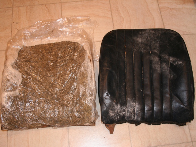
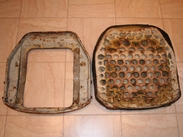
I decided to powder coat the metal frame in light grey rather than re-plate it. All that was required was to remove the old vinyl top and clear off any remaining contact adhesive. At some time in its history the car must have been resprayed as there was quite a bit of overspray on the outer two air ducts. I still can’t work out why, as it would have been harder to get overspray there than not! However the overspray came off fairly easily after a good scrubbing.

First the plastic ducts must be refitted into the slots in the metal frame, before bonding the vinyl dash top to the metal frame using high temperature contact adhesive. Once glued in place the edges were softened using a heat gun which allowed them to be moulded to the shape of the frame before being glued to the underside. The final tasks were cutting slots in the vinyl for the air vents before refitting the surrounds and riveting the map bulb holder back in place.

Map light bulb holder

The vinyl only needed cutting at the dashtop ends to enable it to follow the curvature of the dash

Heat can be used to make the vinyl more pliable so it can be wrapped around the edges

One of the popular upgrades many owners are making is to improve the dash lighting by replacing the incandescent bulbs with LED strips. The backlighting of the gauges and the map lighting were fairly poor at best and the bulbs also generated a reasonable amount of heat. Therefore my next task is to install white LED strips to replace the map light and install coloured LED strips in the gauges.

Completed dashtop

Air vent surrounds refitted

Nov 112012
 

The lower heater pipe was damaged when it was removed from the bulkhead so it needed to be replaced. Unfortunately the suppliers don’t offer the individual pipes (what a surprise!) so I had to buy the complete set of three pipes.

This should have been the end of my woes but sadly it was far from it! While shifting the various parts in storage, some weighty items were put on top of the new pipes and the new lower pipe was bent beyond use. Another Tourettes moment!

At this point the going rate for new pipe sets, which are essentially only a few bits of bent copper pipe, was the best part of £70. Dick Turpin would have been proud of that robbery! So I ordered sufficient 1/2″ copper pipe to remake the offending pipe myself.

The problem I hadn’t envisaged was that my small pipe bender didn’t go up to 1/2″ pipes and my normal plumbing pipe bender couldn’t provide the necessary tight bend that was needed. Due to the lack of space in the bulkhead the bends in the lower pipe have a very tight radius. I was stumped!

I turned to a friend who works in motorsport to seek help. Fortunately he offered to have a pipe made up, however that was far from the end of the problems! I handed over the remnants of the bent replacement pipe, the new copper pipe and the dimensions.

The repro pipe which I'd stupidly bent the repro pipe beyond use and it's replacment

After a few emails confirming dimensions etc, the replacement pipe was ready for collection a few weeks later. It didn’t fit …. it was slightly too long.

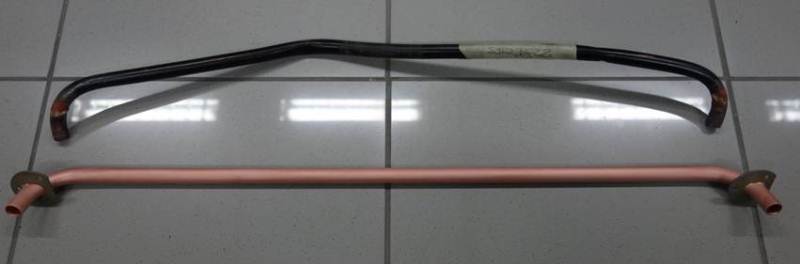
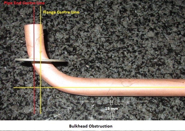
What I’d failed to mention was the bent pipe I’d supplied as the ‘template’ wasn’t the original pipe and I’d not trial fitted it. Like most of the repro parts it looks ok on the surface. That is until you get round to fitting it! The bends in the repro part weren’t tight enough and the flanges had been brazed mid-bend. It would never have fitted and so using it as template to replicate the require bend wasn’t such a good idea! The replicated bend on the right shows the probelm.

Ideally the distance between the Pipe End centres (red) and the Flange centres (yellow) needs to be the same, or at least much closer than they were. The Flange centres distance is obviously set by the spacing between the two bulkhead holes, which are only just large enough to get the pipe ends through. If the Pipe Ends centres distance is greater by any more than 1-2mm then the ends will not fit through the bulkhead holes. Some leeway is available as the pipe can be flexed over its length.

The fitting issues were reported back so I needed to order some new copper piping for Pipe Version 2. I re-ordered the copper piping from the same supplier requesting the same order as before – 30″ of 1/2″ copper pipe. For some reason, only known to the ex-supplier, the pipe was delivered in three small pipes of 10″ as they price it per 25cm! Beyond belief!

I found another source of 1/2″ copper piping however they had a minimum order of 3 metres. Even so, it was still cheaper than 30″ lengths from ‘craft’ retailers. A few days later an articulated lorry turned up with a huge 3m cardboard box with said pipe rattling around inside! This was getting like a farce in one of Tom Sharpe’s Wilt novels!

Oct 112012
 

Wiper arm spline drive
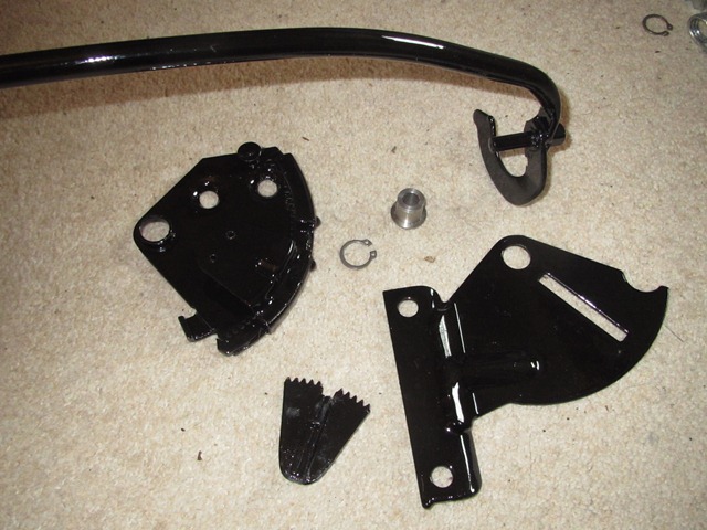
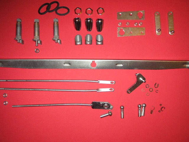
The general consensus from people who have gone through a full rebuild is that one of the first tasks is to fit the various pipes and components within the bulkhead, before access becomes too restricted. So I set to work on the wiper rack. It was working fine but had started to show signs of rust so I decided to smarten it up. Yet again, in my enthusiasm to press on, I forgot to take some decent before photos. The only difficult part during the dismantling was the removal of the rear brackets from the three splined drive assemblies, which needed to be pressed off. The rest of the parts were simply secured by nuts or circlips.

Splined wiper blade drives - the central drive (uppermost) has a spacer between the drive and the rear bracket
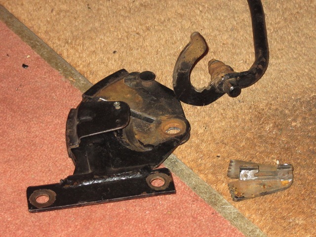
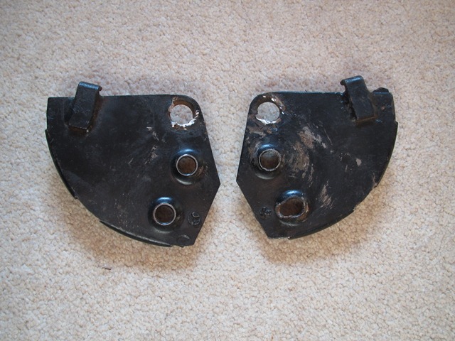
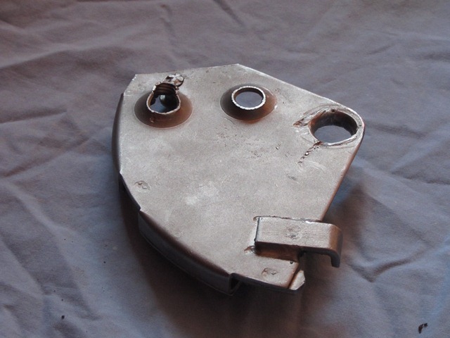
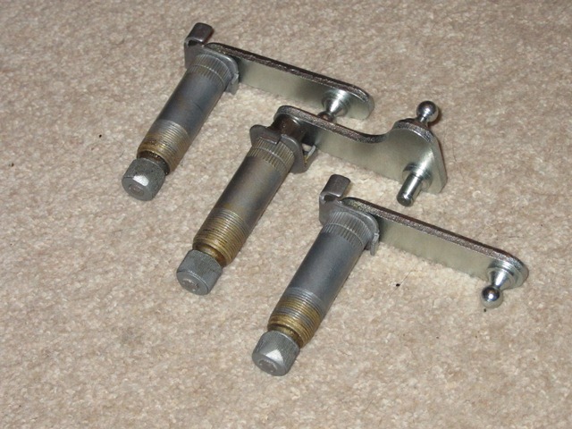
The wiper arm splines on each of the three splined drives weren’t in the best of shape but were still serviceable. Which is just as well as the only replacement I could find was for a fully remanufacturer rack. Due to the shape of the rack, the central drive has a longer shaft than the outer two and so has a spacer fitted between the drive and the rear bracket.

With the exception of the angled bezels and chromed parts, the individual parts followed the now standard cleaning process: immersion in a citric based rust remover overnight, wire brushing, zinc plating/passivation and finally coated with Gtechniq S1. Meanwhile the outer bezels and retaining nuts had been sent off to be chrome plated.

The synchronisation of the rotation of the three splined drives is achieved by two connecting rods, with the central drive also having a connecting rod to the wiper motor to provide the drive. At each rod end is a ball-joint fitting which is secured by a small, horseshoe shaped, snap-lock clip shown below. Unfortunately one of the tiny snap-lock ‘ears’ made a break for freedom and, despite a hands and knees search of the living room carpet, was never to be seen again! The only option available was to purchase a complete socket unit which included the clip and the inevitable robbing by the E-Type parts suppliers!!

Original & new snap-locks Wiper rack components Reassembled splined drives

The original snap-lock clip on the right and the rather expensive complete socket unit, on left

Wiper rack parts plated and chromed, ready for the rebuild

Rear brackets reassembled onto splined drives

The connecting rods are connected to the central wiper drive by a series of spring washers, nylon guides and secured with a circlip. All very straight forward. All that remains is to fit the rack and connect the central drive to the wiper motor. I think it will be necessary to fit the washer jets and tubing before the rack as there’s not a lot of room in the bulkhead.

Refitting parts order Connecting Rods refitted Completed wiper rack

Sep 072012
 

The first task to complete on the newly returned bodyshell was a thorough rustproofing of all the various cavities. I’d already got a 5 litre tin of waxoyl, so I chose to use this rather Dinitrol, which often has good reviews. I actually ended up using 10 litres as most of the cavities were covered within an inch of their lives!

The rustproofing gun purchased from a local auto factors was a good investment as it had an 18″ flexible nozzle to allow spraying deeper into the various cavities. The general advice is to heat the waxoyl and/or thin with white spirits to help it to flow into all the nooks and crannies. So all that remained was to wait for a suitable, hot, sunny day.

Working front to rear, the areas to be treated were:

  • Bonnet
    • Headlight areas behind the sugar scoops
    • Bonnet Undertray, especially behind air intake lip
    • Bonnet Air Channels
  • Bulkhead
    • Behind bulkhead side panels, via hole either side in engine bay
    • Dash area of bulkhead
    • A-posts
    • Heating vents – not entirely sure whether this will prove to be wise!
  • Cavities accessed from interior
    • Sills – via the three holes in each inner sill
    • Inside of transmission tunnel
    • Doors, especially frame to skin join
    • B posts
    • Closed sections behind seats – which would require access hole to be drilled!!
  • Boot area
    • Inner Rear Wheel Arches
    • Boot floor strengtheners
    • Rear light/number place section
    • Bootlid – the frame and boot skin joint, hidden by frame
  • Miscellaneous
    • Rear Chassis Legs (IRS support brackets)
    • Chassis Floor strengthening sections under car

The rear wheel arches and the bonnet/wing joints will be done with a brush towards the end of the rebuild.

Bulkhead holes were masked to stop overespray covering the entire engine bay! Yet more masking ....

Finally there was a break in the dreadful British summer and decent weather coincided with a free weekend. The various holes in the bulkhead and body were masked in an attempt to limit overspray.

The areas to be drilled for the access holes were masked to stop 
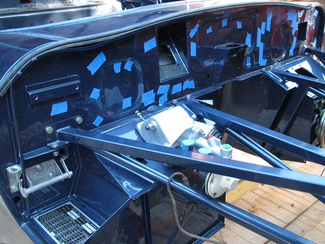
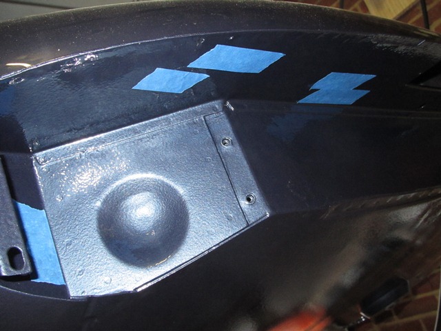
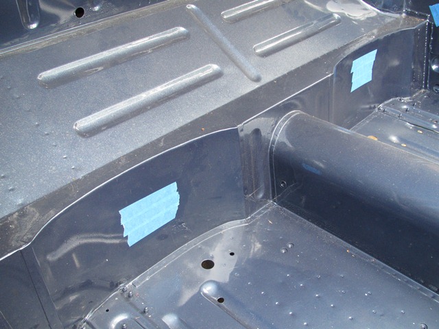
The only problematic cavity is the closed box section in the rear bulkhead, immediately behind the seat bases. I could either leave alone and risk it rusting from within or drill access holes in my lovely painted bodyshell.

Taking others advice from the E-Type forum, I decided it would be better to protect it as the access hole could be plugged with a blanking grommet which would eventually be covered by the interior trim.

The area around the planned access holes was masked to help protect the surrounding area during drilling. A small pilot hole was drilled before using a 19mm core drill bit to cut the final access holes. Fortunately the holes were fairly neat and tidy but I didn’t enjoy drilling my fresh paintwork!

The rustproofing gun and heated waxoyl ready for spraying Closed box sections access holes were drilled to allow the cavity to be rustproofed The headlamp area was given several 'generous' coats of waxoyl, followed by a final coating by brush.

The 5 litre tin of waxoyl had been stored for several years during which time all the solid particles had settled to the bottom. So I emptied the entire tin into a large plastic container and added a small amount of white spirit. It was then heated in a sink of boiling water before being mixed thoroughly using a mixing paddle.

A 2m length of plastic tubing was used to feed the gun with waxoyl. The aim was to give me sufficient reach to get the gun into various cavities without having to continually move the waxoyl container. Fine in theory but far from it in practice!


This caused several problems. The first was that the tube in the waxoyl became soft due to the heat and also appeared to swell (I assume absorbing some of the white spirit). In its softened state it had a tendency to bend sharply, pinching off the supply. This resulted in what can only be described as a backfire causing the waxoyl to be propelled from the container, covering everything in sight!

The second problem was that if spraying was stopped for even a short period, eg moving the container to a new location, then the waxoyl would solidify in the tube. Therefore everything had to be re-heated a number of times.

For the second tin, a shorter length of tube was used and the waxoyl was left in the tin and the tin placed in a container of hot water. This proved to be much more successful.

All that remained was to clean the car as every single panel appeared to have been the victim of the backfiring problem!

Aug 312012
 

The section in the service manual for removing the independent rear suspension (IRS) unit gave the false impression that it was simply a matter of disconnecting the handbrake cable, the hydraulic pipe and prop shaft, undoing the roll bar mounts and knocking off the radius arms. The IRS cage could then be lowered after unbolting the four cage mounts.

It probably is that simple for well maintained cars but mine had seized solid, resulting in bloodied knuckles and much cursing. In fact I couldn’t even get the wire wheels off as they were rusted to the hub splines! The brake connections and prop shaft were fairly easy to undo but everything else was struggle after struggle! The radius arms connect to cup fittings secured to underneath of the floor pan by what look like rivets. However the radius arms had well and truly rusted to the cups. Wooden wedges were hammered in but they still refused to budge.

I later found out from the E-Type forum that they are not rivets but something called Huck bolts, which are designed to shear in the event of an accident. I also found out others’ tricks to release the radius arms from the cups once the retaining bolts have been removed. Too late for my removal but no doubt they’ll be very useful in future. The first is to drive the car slowly backwards and forwards, with the aim that the changing loads breaks the radius arm/cup bond. The second is to chock the rear wheels and then jack up the front creating a load in the radius arms.

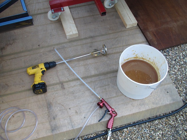
I briefly tried applying heat but all this did was burn the rubber bushes, producing acrid smoke. They eventually came free after applying penetrating oil over a period of several weeks and then jumping up and down on the end of a very long lever, inserted between the floor pan and the radius arm. To the untrained eye, the jumping up and down in a frustrated, childish manner while shouting ‘aaaargh!’ might have come across as a method of last resort …. but it worked!

The next setback was the removal of the roll bar. The bolts securing the mounting brackets were also seized but as they angled slightly downwards it wasn’t possible to apply penetrating oil so that it could soak in. Again I tried using localised heat but, like the radius arms, the bushes started to burn. By this time patience was in short supply, so I gave up and ground off the bolt heads to release the roll bar brackets.

The bolts securing the four IRS cage mounts had also rusted but fortunately they could be still undone. The main problem was the confined space so initially they could only be undone a 1/4 of a turn at a time. As I’d been unable to get the wheels off, it was rather an unconventional removal. Wooden blocks were placed under the cage’s base plate and the car raised away from the supported IRS.

The final dismantling of the IRS was equally unconventional for the same reason. The wheels and hubs were removed with the drive shafts and lower wishbones still attached and taken to a local garage so the hubs could be pressed out of the wheels. There was quite a build up of oil on the differential which suggested some of the seals might have perished. Although they’re interchangeable, and I didn’t know at the time, the aluminium hub carriers are not correct for the E-Type, which should have straight rather than sculptured sides.

 Posted by at 8:49 pm