Jun 172012
 

The fuel and brake lines were other items that were to be replaced as a matter of course during the rebuild. I had intended to purchase lengths of piping and make the individual pipes myself. However the cost of decent pipe flaring tools, able to achieve consistently good joints, are considerably more than complete kits.

So I’d purchased a brake kit from Automec, a similar fuel line kit from Hutsons and a pipe bending tool. Both kits were supplied in copper rather than bundy or cunifer which is closer to the original look. So I’ll have to see how they look on the car and I may revert to fabricating my own in cunifer; an alloy of Copper (Cu), Nickel (Ni) and Iron (Fe).

More importantly, I subsequently found out that copper brake pipes are banned in countries like Australia and the US, where cunifer is the norm. Apparently the copper pipes are susceptible to work hardening over time which can lead to fracturing. The introduction of Nickel and Iron addresses this problem. I think more research is needed especially as it’s a safety issue.

Back to the pipes … the problem with the kits is that they are fabricated from coiled piping. In order to get neat, straight pipe runs they need to be straightened before forming into the correct shapes.

I found an article on an American car site with a rather over-engineered process for straightening coiled fuel pipes. I had a spare afternoon so I thought I’d give it a go. The main point is that the coiled fuel pipe should only be straightened/bent in the same plane as the direction of the original coil.

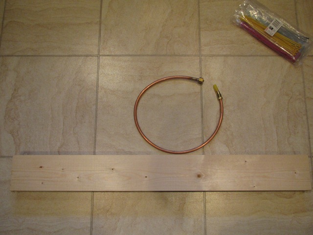
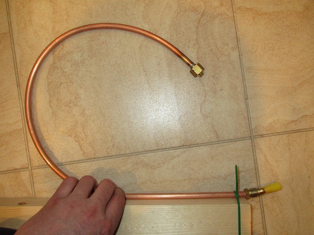
The first step is to lay the coiled pipes on a flat surface and uncoil them against a straight edge, therefore ensuring additional bends in other planes are not introduced. Once released, the pipes will spring back to some extent in the direction of the original coil so the pipes will now form an arc.

Trial run with the shorter engine bay 5/16″ fuel pipe

Long boot to engine bay 5/16″ fuel pipe

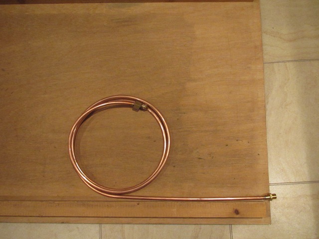
The second step involves deforming the pipes beyond a straight line so that this time, when they spring back, they (hopefully) return to a straight pipe. As it happens, the pipes need to be bent beyond the straight line to exactly the same radius as the arc of the now uncoiled pipe.

I used two pieces of old shelving and some 9mm cladding, the latter would act as channel down the centre of the form. I guess you could just use one board against a flat surface.

The radius of this arc is determined by the pipe thickness and the diameter of the original coil. Therefore, for a given pipe size from the same original coiled length, the arc radius will be the same regardless of pipe length.

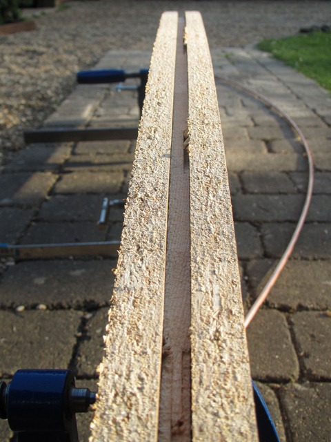
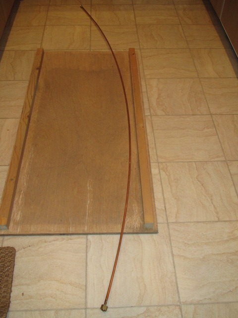
The final step is bending the arced pipes over the form. Starting at one end, position the pipe arcing away from the form but in the same plane. Then bend the pipe around to produce a straight pipe when released. However be careful not to allow the pipes to rotate when doing the final step.

I thought the results were quite good for a pleasant afternoon spent taking a sledgehammer to crack a nut!

Jun 142012
 

It’s fairly common for the bootlid springs to wear and eventually fail. Mine were certainly no exception and the bootlid had never sprung open of its own accord. Each spring should consist of a pack of five leaves but the majority had worn so thin that they’d sheared in two. Hence the lid’s unwillingness to open.

I’d read Eric Capron’s very useful article on replacing the bootlid springs and so it was a job I really wasn’t looking forward to! I’d been meaning to ask Hutsons to do this before they returned the painted bodyshell but, in the excitement of finally having the car returned, I forgot to mention it.

As well as a variety of implements to prise open and hold the leaves apart, it’s a jolly good idea to use some heavy duty protective gloves. Once several leaves have been added the spring force is quite strong and the leaf edges sharp enough to do serious mischief to any fingers left in the way.

The first task in constructing the spring packs is to get the 3/16″ bolt on to the first leaf. I deviated from Eric’s guide as I found it wasn’t that easy to open the leaf sufficiently to insert the bolt with the leaf clamped in the vice. This was partly due to the fact that the vice really needed to be clamped securely to a bench rather than free standing, which made the whole process far more difficult.

To start each leaf, the outer end was pushed until there was just a sufficient gap to insert a flat-bladed screwdriver. The screwdriver could then be turned through 90 degrees, lifting the leaf end away further. This allowed it to be slid over the vice’s swivel lever and the screwdriver removed, see the photos below. A solid bar passed through the centre of the leaf could then be pivoted on the vice body to prise it open. The other end of the swivel lever was hard against the vice body so that it couldn’t rotate.

First leaf : this only needs to be opened sufficiently to insert the washer and bolt. This was quite fiddly and would have benefit from a second pair of hands.

A screw driver was used to prise away the leaf end Inserting the bolt was very fiddly With the bolt in place, the remaining springs can be added to complete the spring pack

Remaining 4 Leaf Springs
The spring pack is completed by adding the remaining leaf springs in a similar manner, one by one. A new leaf was opened as before and placed on the vice swivel lever so that it could be prised open using the bar. This time the leaf needs to be prised open much further so the whole of the first leaf can be inserted and the bolt end passed through the hole in the new leaf … it’s much more fiddly than it sounds!

Once inserted, ease the pressure on the bar allowing until it can be removed. It’s a very good idea to loosely fit a retaining nut at this point otherwise the new leaf is likely to slip off the bolt. Now put the bar through the first leaf and prise open. In doing so, the new leaf will also open and finally pop into place. The process is then repeated until all five springs have been added.

If was a surprisingly fiddly job but I suspect the hardest part will be fitting them to the boot hinges. I’ll put that off as long as i can!

Apr 242012
 

As with all the other electrical units, the alloy parts were was ultrasonically cleaned and then sprayed with Gtechniq S1 SmartMetal while the other steel parts were zinc-nickel plated. The next two tasks were to sort out the gearbox lid which had been distorted and also to strip and paint the yoke.

The offending motor gearbox lid after several attempts at heat shrinking
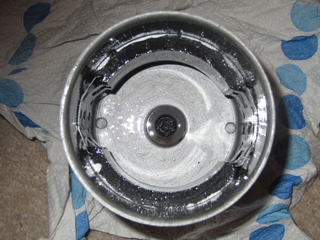
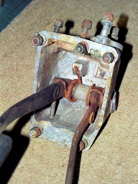
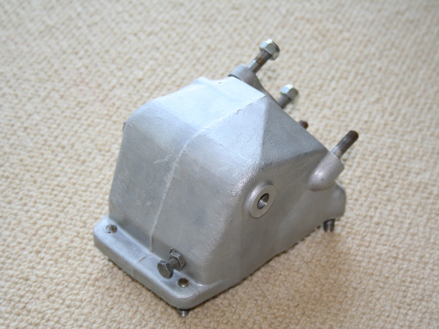
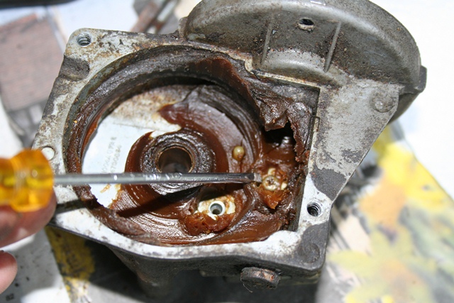
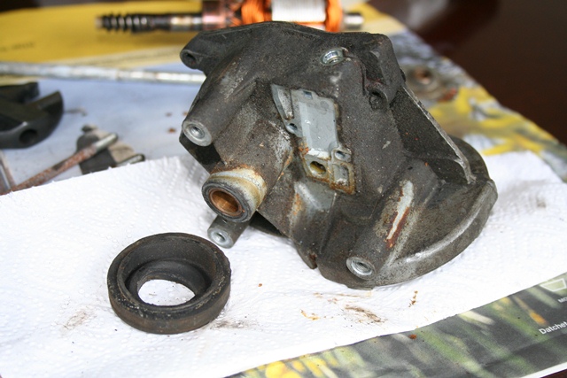
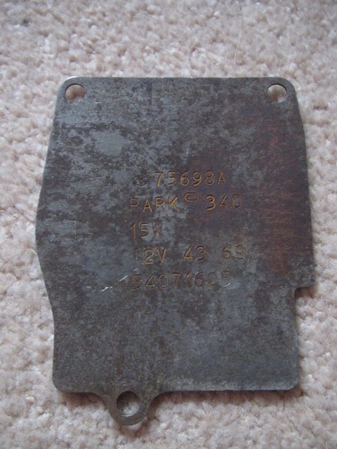
The centre area of the gearbox lid has been stretched at some point. Therefore its outer perimeter no longer made a continuous seal and so would allow water into the gearbox housing.

The suggested solution was to heat shrink the centre section of the lid to reverse the deformation – heating the centre of the lid to near red heat and then rapidly cooling. After several attempts of heating the lid with a gas blow torch and cooling using a can of compressed CO2, all I succeeded in doing was to work harden it in exactly the same shape as before. Aaaaaaargh!

It probably needs to be heated to a much higher temperature using oxy acetylene. In the end I cheated to avoid holding up the rebuild and obtained a replacement lid. When I get time I’ll give it a proper go at flattening the lid, as I would like to keep the original with the correct stampings.

The wiper motor yoke painted in silver hammerite .... at some point I'll repaint in the correct colour
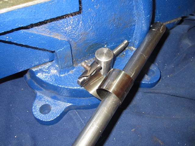
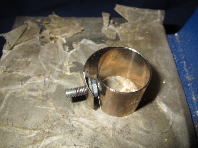
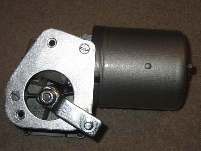
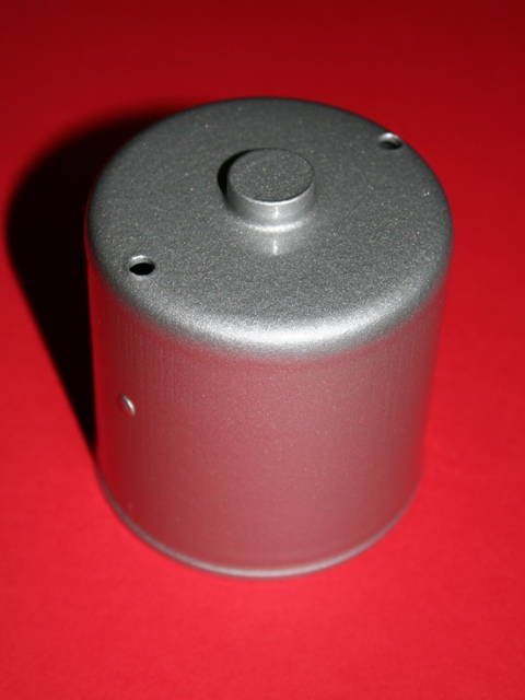
Next up was the yoke which contains the two permanent magnets. The magnets can be removed by lifting the retaining clips so the yoke could then be shot blasted before being painted in silver hammerite. I was quite pleased with the finished article even though the silver hammerite was not quite the correct colour.

During the refurbishing of the cooling fan motors I had found a dark silver hammered paint from Rust-oleum, which is very similar to the orginal colour. At some stage I will re-paint the round bodied yoke but decided to put it off for now. Mainly because of the difficulty I’d had getting a good finish with the Rust-oleum product.

Fortunately the armature wasn’t in such a bad state as those in the cooling fan motors and so all that was required was some light wire brushing and polishing before the S1 SmartMetal coating. I had investigated the availability of new brushes and parking switch units but these seemed to be rather difficult to get hold of. Therefore when I spotted a ‘new, old stock’ brush unit for sale I thought I’d get it as a spare for the future. However I’ve not yet found anyone who can supply the parking switch units.

Cleaned armature Triple Brushes Wiper Motor Parts

The armature was wired brushed to remove the worse of the rust. It was then polished and finally sprayed with Gtechniq S1

The armature brushes and parking switch unit

The wiper motor compentent ready for the rebuild, including the spare armature brushes unit

The rebuild starts with installing the armature brushes and parking switch unit, as these are wired together. The brushes are secured by three small setscrews and the connecting wiring passes through a notch in the motor gearbox housing.

The parking switch is secured by two setscrews from the inside of the gearbox compartment, as shown in the middle photo below. This also shows the protruding parking switch plunger which is activated by a cam on the underside of the gear wheel. The cam positioning is such that it operates the switch when the wiper blades return to their normal rest position.

First fit the brushes Parking switch attachment ACF50 applied to Yoke

The brushes and the parking switch unit are the first to be fitted

The parking switch is attached by two setscrews from inside the gearbox housing. Note the switch plunge which operates when the wipers return to their normal rest position

The interior of the yoke was sprayed with ACF50 which provides a good protection from moisture

After several attempts at fitting the armature and yoke, I found it easier to first fit the armature into the brushes and motor gearbox and then fit the yoke. With this approach its was necessary to hold the armature’s worm drive from within the gearbox so that, when fitting the yoke, the yoke’s magnets didn’t pull the armature out of the brushes. Also don’t do what I did and forget to fit the plain washer between the armature and motor gearbox housing!

Care was also needed in making sure that the thrust and fibre washers were correctly seated in the yoke bearing housing. The easiest way to do this was to join the two with yoke positioned so the ‘bearing’ housing was facing downwards.

Initially I tried to put the armature into the yoke and then attach them both to the motor gearbox. However the problem was it was then difficult to withdraw the three sprung brushes at the same time as inserting the armature, because the yoke restricted access to the brushes.

The middle photo below shows the arrow head marking on the motor gearbox and a corresponding line on the yoke. These need to be aligned when refitting. Also shown is the threaded armature stop. This was then screwed into the gearbox housing until it touched the nylon cap on the armature shaft, before being backed off a 1/4 of a turn.

Next fit the armature Alignment markings Belleville washer goes here

The brushes were then withdrawn to allow the armature to be inserted

The markings on the motor gearbox housing and the yoke must be aligned when re-fitting

The Belleville washer provides pre-load for the armature shaft

The Belleville washers is then positioned within the gearbox before inserting the geared output shaft. The rest of the gearbox was then filled with grease before the output rotatry link and gearbox lid were refitted. The rubber moulding sealing the output shaft area had hardened and split.

At the time I dismantled the motor, it was one of the few parts that wasn’t being remanufactured. Probably because it was only used on the Series 2. However by the time I has started the rebuild, one of the suppliers had made a small batch so I decided to grab one while still available.

Re-packed with grease Output rotary link Motor rebuild completed!

The geared output shaft (just about visible) was inserted and then the remaining space packed with grease

The output rotry link was refitted which also secures the geared output shaft. Although I'd forgotten to insert the rubber seal first .... so I'll have to refit it

The completed wiper motor

The only thing that remains is to adjust the various wiper motor & rack linkages which can only be done once they’re installed in the car. People usually leave the installation of the windscreen until the latter stages of a rebuild. I guess this is because it would restrict access to dash area. However I’m tempted to install the windscreen as soon as the dash wiring looms and dash panels are in place. Therefore I’ll be able to adjust the linkages before the bulkhead access become restricted.

Apr 242012
 

I was surprised how rusty the clutch pedal and pedal springs were seeing it’s inside the car and underneath the aluminium pedalbox housing. I’m assuming this must have been as a result of condensation. Once it’s complete I’ll give the inside a covering of ACF50 to give it some protection. There’s nothing worth noting on the dismantling as the pedals simply rotate on a shaft through the pedalbox.

The pedalbox was renovated before I’d come across the company that ultrasonically cleans alloy components, so it was shotblasted and then coated with a lacquer product sold by Eastwood to stop surface oxidisation. The pedal arm, foot pads and springs were also shot blasted and then powder coated.

The rebuild was fiddly mainly because the pedal springs are quite strong so it’s difficult to align everything while pushing the shaft into position. The final washer had a tendency to drop out at the final moment! It made sense to cover the shaft and mating surfaces in plenty of grease.

I was surprised that the brake light switch is actually part of the hydraulic system, actuated by hydraulic pressure when the brake pedal is pressed. Some have reported problems with the response of this switch and have therefore either replaced it or supplemented it with a mechanical microswitch operated by the brake pedal.

While the car is apart and the looms are being put in place, it makes sense to install both a hydraulic switch and a microswitch in parallel, to build in redundancy. All it would require would be to fabricate a bracket to hold a microswitch in the pedalbox housing. I’ll do this as part of the final electric fitting when the lights are installed.

Apr 152012
 

Hutsons have fabricated wheeled trolleys so bodyshells can be easily moved between the body repair, paint preparation and spray booth areas. They’re designed so the shell is at a reasonable height to work on without the need to stoop.

Once completed, the bodyshells are then delivered bolted to the trolley which posed the first problem for the rebuild. How to get the painted shell off the Hutson’s trolley and onto my waiting axle trolleys.

I had initially planned to do the body work myself and had started to make a rotisserie during the dismantling stage. Its base was a rather substantial affair, built out of lengths of 150mm mild steel channel. The car was delivered to Hutsons on the frame, but as I wouldn’t have further use for it, I left it with Hutsons to dispose of or use as they wished.

They’d put it to good use. When the bodyshell was delivered, they had modified their lorry’s tailgate so the long lengths could be bolted on to act as ramps. Their trolley could then be rolled down the ramps in the channels to safely deliver completed shells.

Unfortunately there wasn’t enough manpower around when the car was delivered to lift the bodyshell onto the axle trolleys. It had to remain on the Hutson trolley while I pondered what to do.

Even with the axle trolleys at their full extension, the bodyshell still needed to be lowered by approx. 40cm. None of the local hire shops had anything suitable to raise and support both ends to allow the trolley to be removed and then lower the bodyshell.

I then looked at erecting four columns of building blocks to support timber cross beams. This would also need two other columns to provide a raised base for the trolley jacks. The number of building blocks needed was mounting rapidly, making it a rather expensive solution for a one off job. I was stumped.

The timely delivery of some timber for a workshop provided just enough wood that could be temporarily half-inched to make supporting platforms either side of the car. Also I wasn’t comfortable attempting to lower the bodyshell on my own and drafted in some much needed help.

An initial recce was duly arranged to plan the lowering however it was soon decided to go for it and the oversized Jenga operation began. The bodyshell had to be raised and lowered a number of times – raise, roll the trolley forward until it hit the platform supporting the jack, lower, reposition the jacking platform. Finally the trolley’s exit route was clear and it could be pulled free.

It this point the bodyshell was in its most precarious position, supported only by three jacks. Not good for the nerves!! The final lowering was relatively simple. The front and rear ends were raised and lowered in turn with a layer of timber removed each time.

With the sun low on the horizon, the bodyshell was at last resting on the axle trolleys. Phew!

 Posted by at 10:04 pm
Feb 232012
 

A rather grubby wiper motor
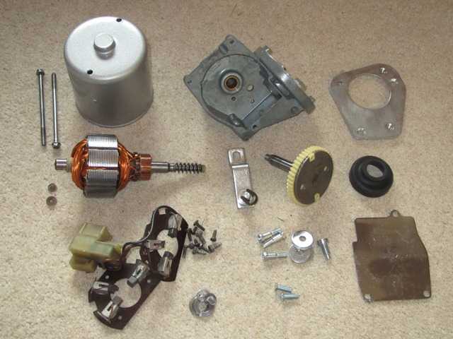
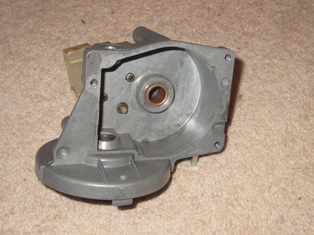
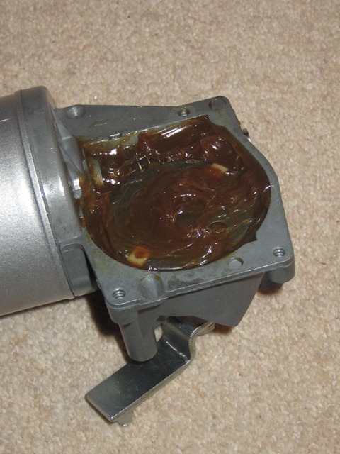
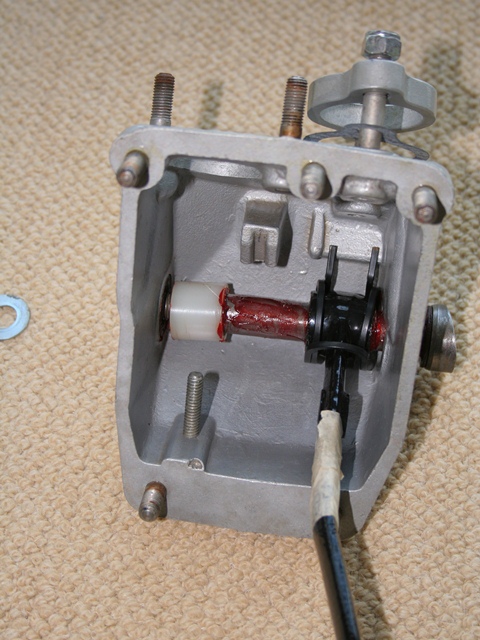
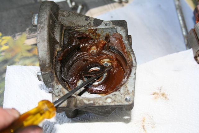
The wiper motor in the S2 is a Lucas Type 15W motor, the output of which drives a connecting rod to the triple wiper rack. From what I can tell the 15W motor essentially works in the same manner as the DL3 wiper motors used in the earlier cars, except that the parking switch is now internal within the 15W.

There are two main sections of the wiper motor; a round bodied section (which acts as the yoke, completing the magnetic circuit) and the motor gearbox. The round bodied section has two permanent field magnets attached to its inner wall and houses the motor’s armature. At the end of the armature shaft is a worm drive that drives the geared output shaft in the motor gearbox.

Worm drive at the end of the armature shaft
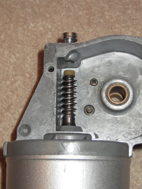
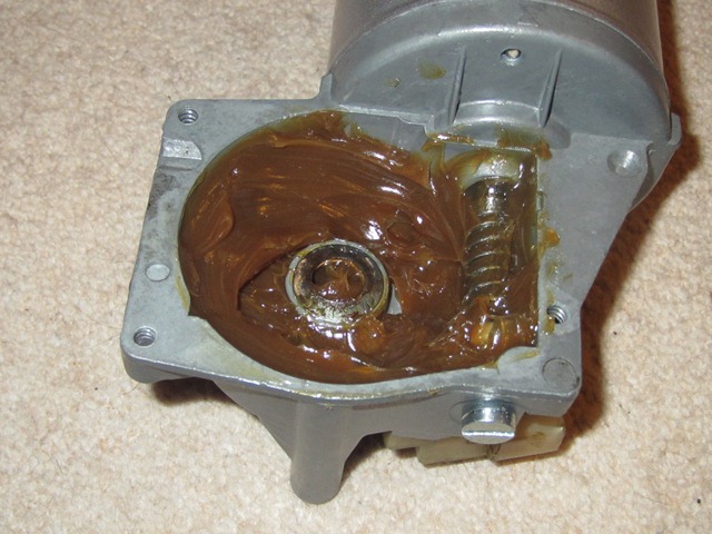
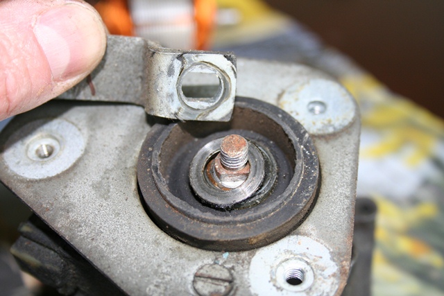
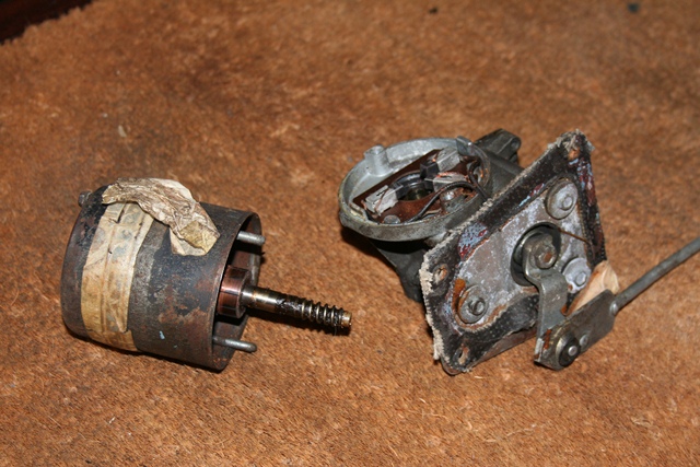
The two long yoke retaining bolts were removed which enabled the round bodied section and armature to be carefully withdrawn until the worm drive is free. Unchecked, the action of the worm drive would pull the armature shaft further into the motor gearbox. A threaded stop screw limits the permitted travel of the armature shaft and there’s also flat thrust washer between the armature and motor gearbox.

The internals were quite badly corroded ... like everything else!
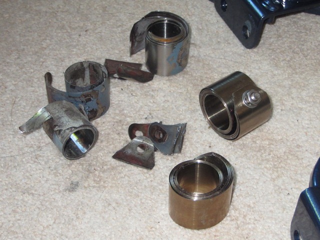
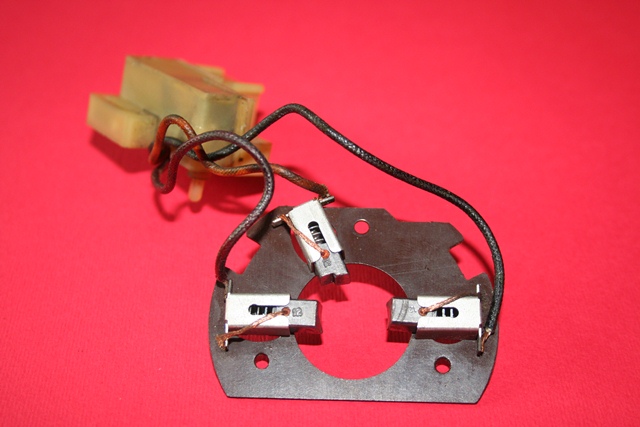
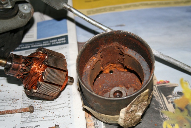
The armature can then be withdrawn from the yoke. Although a reasonable amount of force is required to overcome the magnetic attraction between the permanent magnets and the armature.

The interior of the yoke was fairly heavily rusted and all the tiny, loose rust particles were now annoyingly attached to the permanent magnets.

The thrust plate and fibre washer in the 'bearing housing'
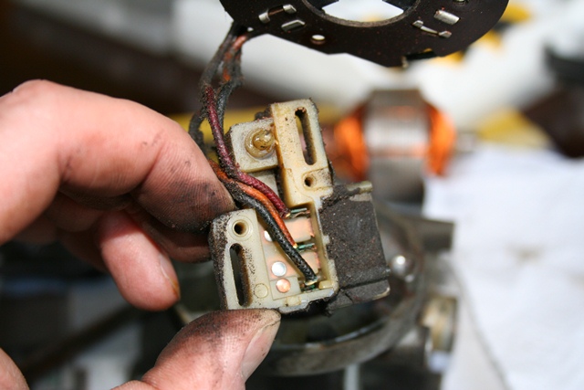
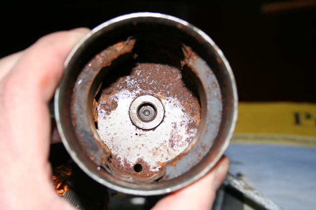
The end of the armature rotates in, what the manual describes as, a bearing housing in the cap of the yoke. However there isn’t a bearing as such. Only a small thrust plate and fibrous washer. I didn’t realise they were there at the time of dismantling so I was lucky not to lose them.

A cover on the main motor housing provides access to the geared output drive. Sometime in the past this cover had become deformed and so it no longer provided a tight seal around its full perimeter (just about visible in the lower photo to the right).

The main housing cover had been deformed creating a gap which would allow water in
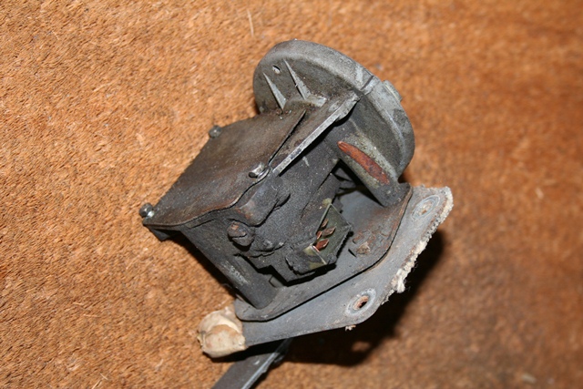
The cover can be pressed back into shape but it immediately pops back, in a similar manner to the lid of an opened jar. I think it’s referred as oil canning and is a result of the centre area of the lid having been stretched.

It should be possible to reverse the stretching by heat shrinking the centre of the plate but that will have to wait until the rebuild.

Removing the cover revealed copious amounts of thick brown grease. I think the grease had dried out long ago and it was surprising the motor was able to turn at all! The rest of the dismantling was very straight forward.

Hardened grease within Worm drive engaged Triple armature brushes

Over time the grease had dried out and hardened. It was surprising the gear could actually turn

Armature worm drive re-engaged for photo. Armature free play is set by tightening a screw, just visible on the left

The

As the wiring between the armature brushes and the parking switch unit is fixed, they had to be removed together. This required the removal of the geared output shaft to gain access to the screws securing the parking switch unit. The output rotary link is removed which enabled the geared output shaft to be withdrawn.

Output rotary link Geared output shaft Parking switch screws

Removal of the output rotary link

Withdrawing the geared output shaft

The removal of the gear wheel provides access to the screws securing the parking switch unit

The geared output shaft has a Belleville washer (conical spring washer) inside the motor gearbox to provide pre-loading and a flat washer between the motor gearbox and the rotary link.

Parking switch wiring Belleville washer Rear rubber seal

The motor has three brushes to provide dual speed operation, which are connected the parking unit

Conical spring washer between the geared output shaft and the motor gearbox

Motor gearbox and the rubber moulding sealing the output shaft had hardened over time

Feb 212012
 

The intention had always been to replace the existing wiring loom, which had had its fair share of modifications in the past. Much of the braided covering had either been caked in oil over the years or had disintegrated. As it was to be replaced and to speed up its removal, I had cut the loom where it passes through the bulkhead and removed it in two sections.

Fortunately, at the time of removal, I wasn’t aware that the loom was in fact made up of a number of looms. So the two sections were boxed and not separated into the individual looms. I was thankful of that when I came to deciphering the wiring diagram against the new looms, as I was able to refer back to a complete loom.

I was fairly confident that I wouldn’t have too many problems doing the re-wiring (pride before a fall?). Just in case, I purchased a copy of a wiring diagram produced by Coventry Auto Components which was to supplement the Jaguar service manual diagram. You can never have too much information ….. unless it’s conflicting or incorrect!

Somehow the old loom had turned itself into a right old bird’s nest while in storage. It took quite a while to untangle it so that it could be laid out, mimicking how it is routed within the car. Armed with a multi-meter and the wiring diagrams, I set about the simple task of labelling the new looms …

… four days later the finishing line was in sight. I had printed a large copy of the wiring diagram which was used to track the progress. Wires that had been identified were labelled at both ends indicating what they should be connect to and then highlighted on the diagram as ‘accounted for’.

The wiring convention used by Jaguar employs colour codes to signify the type or purpose of the wire, eg green for a regulated, fused source. Therefore a loom would often have a number of wires of the same colour. Once a wire disappeared beneath the loom’s braided sleeving, it wasn’t always obvious which of the similarly colour wires reappearing was it’s other end! So a multi-meter, set in continuity mode, was extremely handy and took out the guess work.

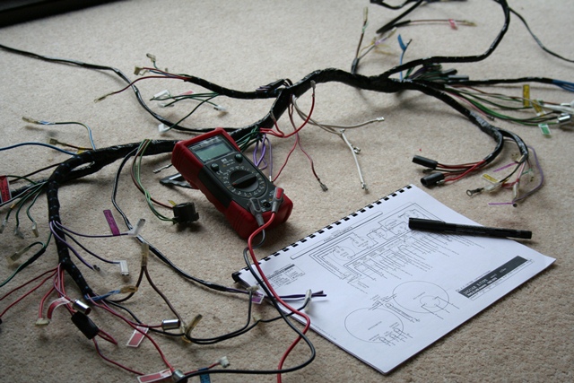
Other issues that, for now, remain unresolved are i) a missing green & brown wire for the reverse light switch and ii) a spare purple & white wire at the centre of the dash. The E-Type forum is very helpful in cases like this as there’s a wealth of knowledge available from the forum members. I was not alone with both the missing and extra wires as one member had decided to use the spare purple & white wire for the reverse light switch. Perhaps I’ll need to do the same.